


1 Technology & Product Development Manager PhD in Engineering Eugene Goli-Oglu Metallurgist Andrei Filatov Commmunication Officer Christian Kragerup
2023
Weldability investigations
Weldability investigations of 120 mm TM+ACC thick heavy plate steel, designed for offshore applications

2 NMLK DanSteel
The relevance of studying the quality of welded joints of heavy plates is driven by the increased technological complexity of production and the progressive increase in requirements for the reliability and durability of welded structures for critical applications.
This paper investigates the microstructural state and mechanical properties of 120-mm welded joints of heavy plates after submerged-arc welding (SAW) with a heating input of 15 and 50 kJ/cm.
The microstructure of critical heat-affected zones (HAZ), their hardness, impact energy and fatigue resistance has been determined and described.
The micro-alloyed steel produced by thermomechanical treatment with accelerated cooling used in the welded joint with Ceq≤0.33% demonstrated a high level of resistance to static and dynamic loads in the welded joint and is recommended for use in critical applications.
The results of the study were used to successfully pass certification tests of heavy steel plates of E36/S420ML quality grade in accordance with the offshore standard DNV-OS-B101, ABS Rules for Materials and Welding and TUV 305/2011/ EU: System 2+.
3
Offshore application, welded joint, low-carbon steel, heavy plate, thermomechanical treatment, heat-affected zone, microstructure, impact test, fatigue strength
4 NMLK DanSteel
5
Heavy plates of low-carbon micro-alloyed steel with a thickness of more than 80 mm are common in many segments of civil engineering. Among the most technologically intensive segments are bridgebuilding, high-rise and offshore construction.

Thick welded joints of steel structures and critical assemblies are the subject of increased attention in research and quality control both on the part of manufacturers and on the part of inspectors of certification societies, who collectively control not only the process and result of welding work, but also the earlier stages of fabrication, including production and testing of heavy steel plates, certification of new types of products, welding consumables, etc.
This is confirmed by numerous profile programs of certification societies [ 1] and national standards [ 2 ] for the certification of welded joints, which allow assessing the resistance of the base metal, the heat affected zone (HAZ) and the weld metal to various static and dynamic loads.
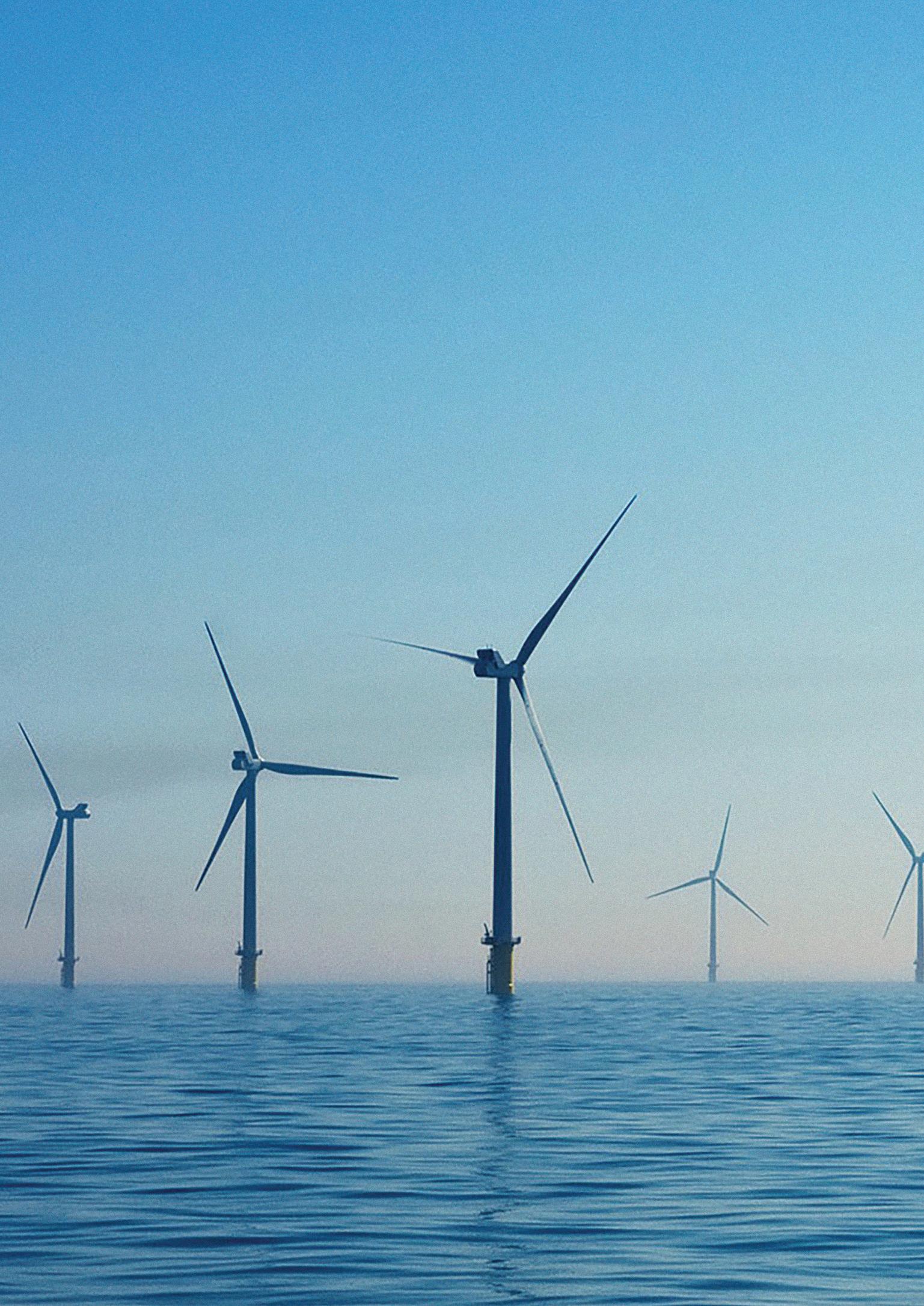
Good examples of structures in which the wall thickness of the welded joint are reaching 120130 mm [ 3 ] are foundations (Fig. 1a) or bases (Fig. 1b) of offshore structures, primarily in the energy sector. In the foundations of bridge structures and high-rise construction, thickwalled joints with a thickness of up to 150 mm can be used as well to a limited extent.
The reliability and resistance to static and dynamic loads of thick-walled welded joints of low-carbon micro-alloyed steel are characterized by the results of mechanical and ultrasonic tests are subject to the established mode of welding, which are determined by the chemical composition, the microstructural characteristics of the HAZ, weld metal and affected areas of the base metal [4].
6 NMLK DanSteel
Introduction
7
The objective
The objective of this work is the investigation of the microstructure and mechanical properties of 120-mm thick welded joints of low-carbon micro-alloyed steel of E36/S420ML quality grade produced at NLMK DanSteel 4200 rolling mill by thermomechanical treatment with final accelerated cooling. The chemical composition and the technology for the production of heavy steel plates, as well as technological regimes and welding procedures, were developed at NLMK DanSteel.
Materials and Methods
Steel from a converter steelmaking process is poured into continuously cast slabs with a thickness of 355 mm, which was used as material for the study. Steel chemical composition, %: ≤ 0.05 C; ≤ 1.50 Mn; ≤ 0.20 Si; ≤ 0.003 S; ≤ 0.007 P; ≤ 0.007 N, ≤ 0.30 Ni. The steel was microalloyed with Nb+Ti, with a carbon equivalents of Сeq ≤0.33%, Pcm ≤0.14%, CET≤0.21%.
The slabs were rolled at NLMK DanSteel 4200 reversing rolling mill [ 7 ] to a final thickness of 120 mm with thermomechanical treatment in three stages, interstage cooling and final accelerated cooling in two stages (ТМ3+ACC2) [8].
The level of the main mechanical properties corresponds to the quality level of E36 / S420ML grades (Table 1) and amounts to yield strength
ReH: 395-405 MPa, ultimate tensile strength Rm: 500-510 MPa, tensile elongation A200: 24-26%. Impact energy KVL-40 in ¼ thickness: 210-260 J. The percentage reduction of area ψz when tested
in the direction of the thickness (Z-test), according to EN 10164, amounts to 72-80%. The result of the ultrasonic test, according to EN 10160, is complying the norm of S3E4. Multipass arc welding (SAW process 121-2) was performed in two variants: with a heating input (HI) of 15 ± 2 kJ/cm and 50 ± 2 kJ/cm as required by DNV-OS-B101 in semi-automatic mode. Welding was carried out by preheating the plates in accordance with the requirements of the standard.
Edge preparation – ½ V at an angle of 45 ± 5 (Fig. 2). With a heating input of 50 ± 2 kJ/cm, the seams of the 120-mm welded joint was filled in 118 passes. With a heating input of 15 ± 2 kJ/cm, the seams were filled in 340 passes.
The maximum temperature between passes did not exceed 200 °C. Series 13 welding wires with a thickness of 4 mm and Series 10 flux manufactured by ESAB were used. At least 72 hours after the end of the welding work, welded plates were sampled for macro-, microstructural investigations and mechanical tests.
8 NMLK DanSteel
Elements of foundation structure (a) of an offshore wind turbine [5] and (b) gas platform [6] with the use of thick-walled welded joints


9
Steel grade Yield strength, ReH, MPa Ultimate tensile strength, Rm, MPa Tensile elongation, % Impact energy KVL-40 in ¼ thickness, J 80 < t ≤ 100 100 < t ≤ 150 S420ML ≥ 370 ≥ 365 470-620 ≥ 19 ≥ 31 E36 ≥ 355 490-630 ≥ 21 ≥ 50 t – plate thickness
Table 1. Requirements of EN 10025-4:2019 and DNV-OS-B101:2021 for the level of mechanical properties of the steel grade
Fig. 1.
a
b
The microstructure
The microstructure of the steel was studied using automated optical microscopes Leica DMiC, Carl Zeiss Axio Observer 7 MAT and scanning electron microscopes Tescan MIRA 3SBH and Scios 2. One-fourth of the thickness of the welded joint in Zone X was examined and described as shown in Figure 2.


The tensile test was performed on transverse circular specimens in accordance with ISO 6892-1 taking into account the requirements of DNV-OS-B101 and DNVGL-CP-0243. The low-temperature impact toughness of welded
joints was determined based on the results of impact using Charpy samples in the transverse direction along the weld metal, fusion line (FL), and at a distance of FL – 2 mm, FL + 2 mm, FL + 5 mm and FL + 20 mm.


The HAZ tendency to brittle fracture was assessed based on the results of Crack Tip Opening Displacement (CTOD) tests, which are described in ISO 15653 and ISO 12135. The grain-coarsened heat-affected zone (CGHAZ) was tested. Test temperature: minus 10 °С.

10 NMLK DanSteel
Fig. 2.
a b
Macrostructure of the investigated welded joint depending on heat input value: (a) – 15 ± 2 kJ/cm; (b) – 50 ± 2 kJ/cm
Heat-Affected Zone in Multipass Welding
Traditionally, the heat-affected zone (HAZ) of welded joints of low-carbon steels of the type under study is divided into four main zones [9, 10]: 1) the grain coarsened zone, in which the temperature of metal during welding is increased above 1100-1200 °С (depending on the chemical composition of the steel), designated as GCHAZ; 2) the fine grain zone, in which complete recrystallization occurs, and the temperature of metal increased above 1100÷1200 °С (Ac3), designated as FGHAZ; 3) the intercritical zone, in which partial recrystallization occurs (Ac3 -to Ac1), designated as ICHAZ; and 4) the subcritical zone, in which the temperature of metal during welding is not increased above Ac1, designated as SCHAZ.
However, in multipass welding, the above zones can be repeatedly layered on top of each other [ 11], thereby forming alternating microstructural states at distances which are equidistant from the central axis of the weld.


When examining thick-walled welded joint in detail, it is possible to distinguish more than 10 zones, including actual critical and conditional critical areas.
These include: 1 – columnar weld metal, 2 –subcritical grain coarsened zone in the presence of influence from other zones, 3 – intercritical grain coarsened zone resulting from overlapping of heat-affected zones, 4 – conditional line Ас3, 5 – conditional line Ас1, 6 – isolated intercritical zones in the absence of influence from other zones, 7 – unit subcritical zone in the absence of influence from other zones, 8 – actual nonvisible boundary of the heat-affected zone, 9 –base metal, 10 – fine-grain zone, 11 – grain coarsened zone, 12 – fusion line


11
Fig. 3.
Scheme of the heat-affected zone in multipass welding with a single bevel ½V in accordance with EN 10225-1:2019
Microstructure of the Welded Joint
The study and identification of the microstructure of the heat-affected zone in multipass welding is a multi-step physicometallurgical challenge due to overlapping of multiple areas with different thermal cycles. Fig. 4 shows a panorama of the microstructure of the main zones of the investigated welded joint with a HI of 15 ± 2 kJ/cm, whose classification is provided in accordance with EN 10225-1:2019 taking into account the scheme shown in Fig. 3 and the location of Zone X in Fig. 2.


The columnar weld metal of the zone of incomplete melting of the weld metal of investigated welded joint (Fig. 4.1) has a dendritic structure and is a mixture of polygonal ferrite and Widmanstedt structures. The average radius of the columnar structure in this case is ~4198 µm (Fig. 2a, Zone X). The average conditional size of one dendrite ranges from 150 to 1200 µm in the direction parallel to the solidification front and from 40 to 105 µm in the direction transverse to the solidification front. The “beads” of each
weld pass are located symmetrically relative to each other. The fusion line (Fig. 4.12) is clearly pronounced and characterizes the transition from the dendritic structure of the weld to the structure of the grain-coarsened overheated zone.
Different morphological types of ferrite and bainite, are observed in the structure of the grain overheated coarsened zone of the heat-affected zone (GCHAZ), when there was no influence of other zones during multipass welding [ 12] (Fig. 4.11). It is important to note the absence of martensitic or bainitic rude packages.
This has a positive effect on the level of low-temperature impact toughness and increased fatigue resistance of HAZ. In the fine grain zone (Fig. 4.10) where complete recrystallization occurs (FGHAZ), the structure contains a mixture of quasi-polygonal ferrite formed during the cooling process in the temperature range from 1100 ÷ 1200 °C to Ac3.
12 NMLK DanSteel
Fig. 4.
General view of the investigated welded joint with a HI of 15 ± 2 kJ/cm and photographs of the main zones
The next important area of the welded joint is the approximate front near point Ac3 (Fig. 4.4). This is the area which is heated to temperature Ac3 that separates the fine grain zone where complete recrystallization occurs from the intercritical zone where large grains are formed as a result of incomplete recrystallization.
The microstructure of this interval represents a transition state from the fine grain zone to the intercritical heat affected zone (ICHAZ) a mixture of fine and coarser grains (Fig. 4.6). This zone, without the influence of the neighbouring zones, is characterized by incomplete recrystallization, due to the achievement of heating and cooling conditions in the range between Ac1 and Ac3. This results in a mixture of fine recrystallized grains and large uncrystallized ferrite grains. Thus, irregularly shaped quasipolygonal ferrite with separate zones of coarse and finer grains is observed in the structure of this zone [ 13]. When several zones overlap, ferrite grains of different shapes are observed in the structure [ 14] (Fig. 4.3). In addition, the intercritical zone is limited to the area with a transition structure of the Ac1 line
with isolated areas of degenerate pearlite (Fig. 4.2). The structure of the base metal (Fig. 4.9) is represented by a combination of quasi-polygonal and polygonal ferrite with minor amounts of pearlite and bainite.
The SEM method was used to study the morphology of ferrite and carbonaceous phases in the area of complete recrystallization (Fig. 5) and in the area of partial recrystallization (Fig. 6). These areas are primarily characterized by the presence of grains of different sizes in the microstructure. Fig. 5 clearly shows recrystallized ferrite grains with an average conventional diameter of ~5.3 µm and a maximum conditional diameter of up to 10 µm and small colonies of degenerate pearlite (Fig. 5b) with an average conditional size of up to 2 µm and a maximum of no more than 4 µm are clearly visible. In the area of partial recrystallization, coarse grains of polygonal ferrite (Fig. 6a) with an average size of ≈16 µm and a maximum size of up to 25 µm are present along with fine-dispersed ferrite-perlite microstructure. The pearlite component is also represented by areas of degenerated pearlite (Fig. 6b).


(Fig. 4.5), which, in turn, is followed by the subcritical zone (Fig. 4.7), where, in the absence of influence from other zones, the structure is represented by coarse grains of polygonal ferrite, as well as a finely dispersed ferrite-perlite mixture. In case of overlapping of several heat-affected zones during repeated heating below Ac1, recrystallization occurs repeatedly, which leads to the formation of a homogeneous ferrite structure
An increase in heat input from 15 ± 2 kJ/cm to 50 ± 2 kJ/cm changed the macroscopic contours of the welded joint in the direction of their significant enlargement, however, it practically did not lead to sensitive changes in the formation of microstructure in the HAZ of the welded joint made of the same material by multipass arc welding. Fig. 7 shows a panorama of the microstructure of the main zones of the welded joint with
13
Fig. 5.
Microstructure of the area of complete recrystallization: (a) – SEM, magnification ×2,000, (b) – SEM, magnification ×35,000

14 NMLK
DanSteel

15
HI 50 ± 2 kJ/cm. It is important to note that in the case of an increase in the heat input, the HAZ zones are less pronounced and have insufficiently clear boundaries due to an increase in the heat input of each new subsequent pass and, consequently, an increase in the mutual diffusion of zones during repeated welding cycles. The average radius of the columnar structure amounts to approx. 8000 µm.
The average conditional size of one dendrite ranges from 235 to 1020 µm in the direction parallel to the solidification front and from 50 to 190 µm in the direction transverse to the solidification front. In the structure, both at the


macro- and microlevels, multiple overlapping of “beads” and their non-symmetrical arrangement is observed (Fig. 2b). It is considered, that when using multipass welding, the overlap effect has a positive impact on macrostructure formation by preserving more heat and reducing the cooling rate of the new pass. The quantitative and morphological features of the zones of the investigated welded joint with a HI of 50 ± 2 kJ/ cm remain most similar to the above welding regime. No critical microstructural components that have a sharply negative effect on the impact toughness of the welded joint have been identified.

16 NMLK DanSteel
Fig. 6.
Microstructure of the area of partial recrystallization: (a) – SEM, magnification ×2,000, (b) – SEM, magnification ×50,000
Fig. 7.
General view of the investigated welded joint with a HI of 50 ± 2 kJ/cm and photographs of the main zones
Hardness of the Welded Joint
According to the results of hardness measurement with HV-5 load, it was determined that the hardness of welded joints both with a heat input of 15 ± 2 kJ/cm (Fig. 8) and 50 ± 2 kJ/cm is at approximately the same level and slightly exceeds the hardness of the base metal. The heat-affected zone is transitional where the hardness gradually increases from the base metal to the weld material. Hardness measurements were carried out in three planes of the welded joint: at the surface, at a distance of 1 mm from the immediate top face of the base metal; at the middle; and at the root of the weld, and also at a distance of 1 mm from the bottom surface of the welded joint.

Fig. 8 schematically shows the areas of hardness distribution and its average values in the welded joint with relative maximum and minimum limits obtained as a result of testing of all submitted specimens.

The level of weld hardness is characterized by the average values of 200 HV5 and 201 HV5 at the top surface and at the root of the weld,
respectively, and 206 HV5 at the core of the weld. At the face of the welded joint, in the immediate vicinity of the fusion line (FL), the hardness level on both sides of the weld is ≈ 194 HV5. At the FL of the weld middle, it amounts to 182/201 HV5, and at the root – to 187/200 HV5. The increased values at the inclined bevel of the weld groove are the result of greater unevenness in certain sections of the fusion line.

At a distance of 2 mm from the fusion line (FL+2 mm), the values begin to level off over the entire thickness of the welded joint, and amount to: 188/195 HV5 at the surface, 191/187 HV5 at the core, and 194/198 HV5 at the root of the weld. The hardness level of the base metal measured at a distance of 60 mm from the fusion line (FL+60 mm) is fairly even and ranges from 173/175 HV5 at the face, to 187/191 HV5 at the middle and 184 HV5 at the root of the weld.

173 184 187 198 187 201 200 195 191 182 206 201 187 195 194 200 195 188 175 191 184 17
Fig. 8.
a b c
Hardness distribution in a welded joint with a HI of 15 ± 2 kJ/cm in accordance with EN 10225-1:2019: (a) – face, (b) – middle, (c) – root
Strength and Impact Energy in the Welded Joint

Tensile and impact energy tests were performed in accordance with the DNV-CP-0243 program for specimens cut transverse to the weld. A welded joint with a HI of 15 ± 2 kJ/cm is characterized by: yield strength (min-max/average) of 397-412/408 MPa, an ultimate tensile strength of 503-504/504 MPa, tensile elongation at break of 16-17/17%, ultimate tensile strength, direct, of the weld metal of 600-620/617 MPa. No fundamental differences in the results for the welded joint with a HI of 50 ± 2 kJ/cm were identified: yield strength (min-max/average) of 411-415/412 MPa, the ultimate tensile strength of 503-505/504 MPa, tensile elongation at break of 15-17/16%, ultimate tensile strength, direct, of the weld metal of 605-620/616 MPa.

Tests to determine the impact energy in the welded joint were carried out in the transverse direction. Values obtained in 5 reference areas of the joint: weld material (WM), fusion line (FL), 2 mm from the fusion line (FL+2 mm), 5 mm from the fusion line (FL+5 mm) and 20 mm from the fusion line (FL+20 mm). Impact samples were
specially made so that the axis of the V-shaped notch corresponded to each of the investigated areas.
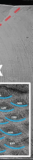
The measurement results show that the values of impact energy in the weld metal for a joint with a heat impact of 15 ± 2 kJ/cm (Fig. 9a) at the investigated depths stand at 152-171 J. At the fusion line, where the structure is characterized by a transition from the dendritic morphology of the welded joint to a GCHAZ, average values of 264 J at the surface and 255 J at the root were obtained. In the weld middle, lower values of impact energy down to 196 J are observed, but then there is a slight increase in the HAZ, where different morphological forms of ferrite are observed in the structure, up to 134 J at a distance of 2 mm and 169 J at a distance of 5 mm from the fusion line, and then, in the zone of the base metal, an increase to 183 J is observed.
The values of impact energy at the face and at the root of the weld continue to increase after the fusion line from 255-264 J at a distance of 2
18 NMLK DanSteel
Fig. 9.
Impact energy curves after testing at -40 °C in the welded joint: (a) – with a HI of 15 ± 2 kJ/cm; (b) – with a HI of 50 ± 2 kJ/cm
mm in the HAZ to 309-304 J at a distance of 20 mm from the fusion line, which corresponds to the base metal with a predominantly quasi-polygonal ferrite microstructure.
For the welded joint with a heat energy of 50 ± 2 kJ/cm (Fig. 9b), the distribution pattern and the range of the results obtained are generally similar to the previous welding regime. The impact energy of the weld material throughout the thickness of the welded joint ranges from 138 to 163 J. The fusion line is characterized by an average value of 273 J at the surface and 281 J at the root, which is slightly higher than in the first welding regime. In the centre along the thickness of the weld, again, a decrease in the values of the impact energy

is observed. A high level of 267-284 J at the face and at the root of the weld is also maintained in the HAZ at a distance of 2 mm from the fusion line. At the core, the values are increased to a level of 158 J.
At a distance of 5 mm from the fusion line, the increase continues at the surface and at the root and reaches a level of 307-317 J, and in the centre a decrease to 129 J is observed, but at a distance of 20 mm from the fusion line, again an increase to 188 J is observed. At the face and at the root of the weld, the results remain at the same high level, and in the base metal area stand at 292-304 J.
Fatigue Resistance of the Welded Joint
The fatigue resistance of the welded joint of the investigated type with a HI of 50 ± 2 kJ/cm was determined at test temperature minus 10 °С by crack tip opening displacement value δ (δCTOD) along the most brittle area of HAZ: the grain
coarsened zone (GCHAZ) near the fusion line. Fig. 10 shows a characteristic graph of crack opening, which characterizes the conditions of crack development up to the moment of critical opening (loss of signal) and the type of a E36

19
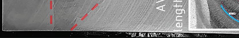
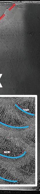
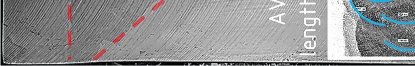
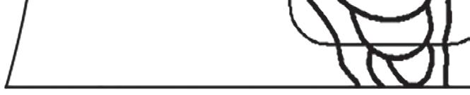
Fig. 10.
Test curve (a) and fracture (b) of the welded joint of the investigated steel grade with a thickness of 120 mm when tested in the GCHAZ zone with δCTOD result of 1.68 mm.
rolled sample with a thickness of 120 mm after the end of the test. At the fracture, five main fracture zones can be distinguished according to the viscous mechanism (marked in Fig. 10b): 1) fracture initiation zone (beginning of crack development); 2) crack development zone; 3) primary zone of rupture; 4) secondary zone of rupture; 5) fracture contraction zone.
GCHAZ of the investigated steel grade is characterized by average values of the maximum applied load before fracture crack development at the level of FmCTOD = 125-130 kN and a δ CTOD average value of 1.36 mm. The results obtained testify to the high fatigue resistance of the welded joint [ 15 ].

20 NMLK DanSteel
The microstructure and mechanical properties of welded joints of low-carbon micro-alloyed heavy plate steel of E36/S420ML quality grade with a thickness of 120 mm produced at NLMK DanSteel facility by thermomechanical treatment followed by accelerated cooling were studied.
The chemical composition, the technology for the production of heavy steel plates, as well as technological regimes and welding procedures were developed at NLMK DanSteel.

The investigated welded joints with a heat input of 15 and 50 kJ/cm are characterized by:
• Low level of carbon equivalents: Ceq ≤ 0.33%, Pcm ≤ 0.14%, CET≤ 0.21%;
• The absence of critically brittle microstructural components in the investigated heat-affected areas;
• Strength at the level of: ReH = 397-415 MPa; Rm = 503-504 MPa;
• Impact energy in the transverse direction at -40 °C in the most critical areas of the welded joint, not lower than 120 J;
• High fatigue resistance of the GCHAZ zone with a δCTOD average value of 1.36 mm;
The results of the study and testing of welded joints were used to successfully passed weldability certification tests of heavy plate rolled products of E36/S420ML quality grade with a maximum thickness of 120 mm in accordance with DNV-OS-B101-2021, ABS Rules for Materials and Welding, with acceptance and verification by maritime classification societies DNV and ABS.
21
Conclusion
1. DNVGL-CP-0243. Class Programme. Approval of Manufacturers. Rolled steel products – nonstainless steel. – Oslo. 2019. 33p.
2. DS/EN 10225-1:2019. Weldable structural steels for fixed offshore structures – Technical delivery conditions – Part 1: Plates. – Brussels. 2019. 64p.
3. Goli-Oglu E., Greisen Z. Production of TMCP steel plates up to 100 mm (Part 1) // Stahl und Eisen. 2020. No5-6. P. 49 – 53.
4. Kazuhiro K. Progress in This Decade and Future Prospects of Welding Technologies on Steel Plates and Pipes // NIPPON STEEL & SUMITOMO METAL TECHNICAL REPORT. No. 119. 2018. 7 p.
5. Goli-Oglu E. Heavy plates for offshore wind // Stahl und Eisen. 2022. Vol. 06. P. 51 - 57.
6. Major Capital Project: Big Foot // Chevron Corporation: [official site]. 2022. URL: https://www.chevron.com/-/media/chevron/projects/documents/BigFoot-Factsheet.pdf (Accessed 2022-05-31).
7. Sarkits I., Bokachev Y., Goli-Oglu E. Production of heavy plates on the rolling mill 4200 NLMKDanSteel A/S // Stahl und Eisen. 2014. No4. P. 57 – 61.
8. Gorni A., Silveira J. Accelerated Cooling of Steel Plates: The Time Has Come. // Journal of ASTM International. 2008. Vol. 5, No. 8. Р. 358-365.
9. Bodude M., Momohjimoh I. Studies on Effects of Welding Parameters on the Mechanical Properties of Welded Low-Carbon Steel. // Journal of Minerals and Materials Characterization and Engineering. 2014. No 3. P. 142-153.
10. European Standard 10225. Weldable Structural Steels for Fixed Offshore Structures – Technical Delivery Conditions. Brussels. 2009. 84 p.
11. Amanie J., Oguocha I., Yannacopoulos S. Effect of submerged arc welding parameterson microstructure of SA516 steel weld metal // Canadian Metallurgical Quarterly. 2012. Vol. 51. P 48-57.
12. Liangyun L., Chunlin Q., Dewen Zh., Xiuhua G., Linxiu Du. Analysis of microstructural variation and mechanical behaviors in submerged arc welded joint of high strength low carbon bainitic steel // Materials Science and Engineering: A. 2012. Vol. 558. P. 592-601.
13. Kim Y, Hwang W. High-Cycle, Low-Cycle, Extremely Low-Cycle Fatigue and Monotonic Fracture Behaviors of Low-Carbon Steel and Its Welded Joint. // Materials. 2019. No 12 Vol. 24:4111. 23 p.
14. Lolla T., Babu S. S. ,Lalam S., Manohar M. Сomparison of simulated heat affected zone microstructures of niobium microalloyed steels subjected to multi-pass weld thermal cycles // Proceedings of the International Seminar on Welding of High Strength Pipeline Steels. CBMM and TMS. 2013. P. 281-297.
15. Choi K.-S., Lee S.-H., Chung W.-J., Hwang H.-G., Hong S.-H., Hong, J.-U. Study of Brittle Crack Propagation Welding for EH40 Steel Plate in Shipbuilding Steel // The Korean Society of Manufacturing Process Engineers. Vol. 18. No. 5. 2019. P. 9–16.
22 NMLK DanSteel
References

23
NLMK DanSteel +45 4777 0333 info@eu.nlmk.com www.dansteel.dk
