PRAIRIE PARK PAVILION
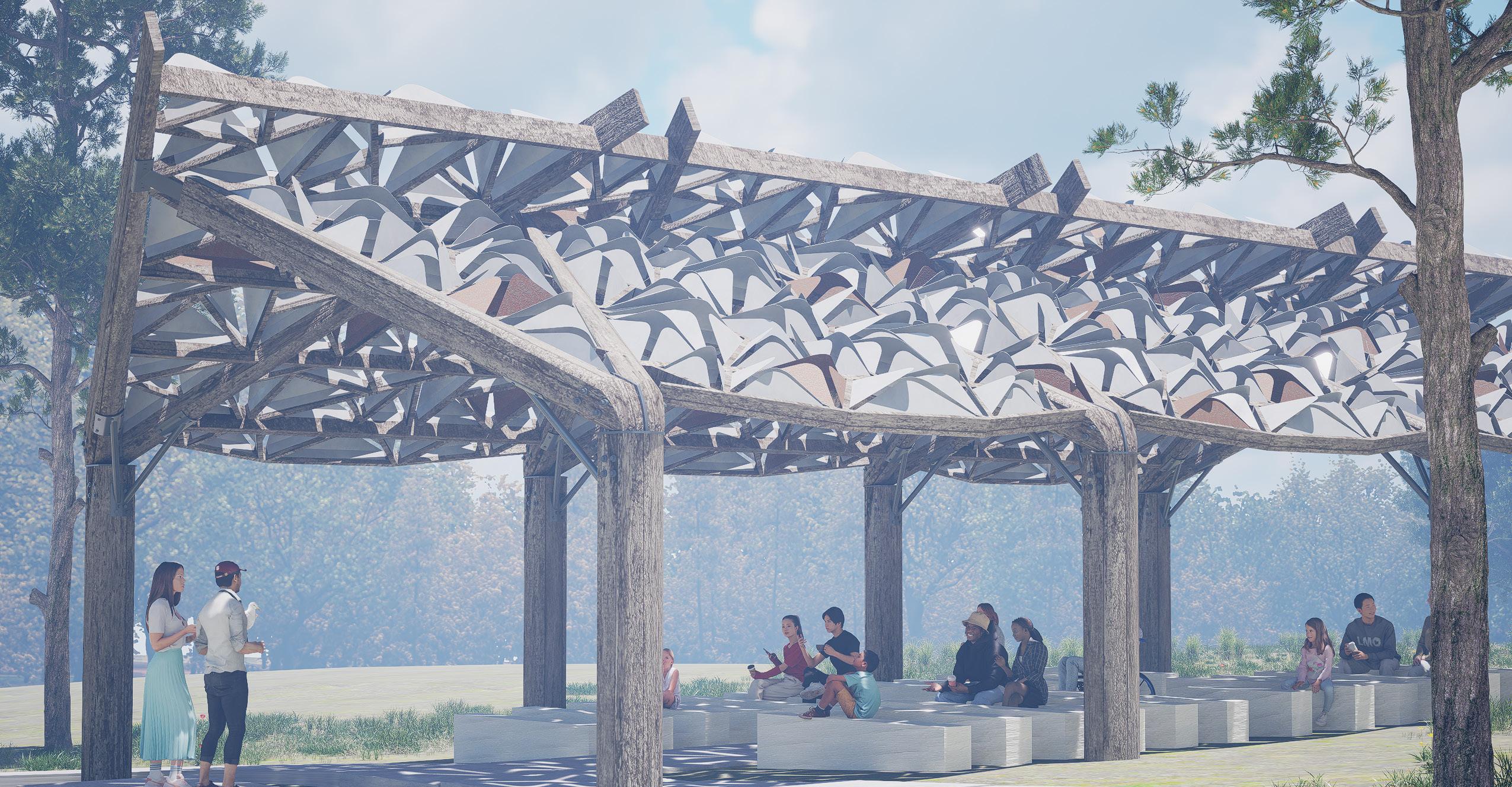
Matthew Garrett ARCH 509
Professor Keith Van de Riet Spring 2024
PROFESSOR
Keith Van de Riet
Susan Hampton
Wynn Bowden
Paige Butterfield
Naałkh DeAsis
Ashley Decker
Emily Dulle
Matthew Garrett
Emma Hamer
Sara Miranda
Christopher Monarres
Sarah Montes
Madison Simons
Alayna Thomas
Melia Whitney
City of Lawrence Department of Parks and Recreation
Prairie Park Nature Center 2730 Harper St Lawrence, KS 66046
Precedent Study
Individual Exploration
Collaborative Solutions + Community
Feedback
Fabrication Tours
Construction Documents Site Layout
Fabrication
Construction + Installation
Opening
work is original unless otherwise noted.
2 3
TEACHING ASSISTANT STUDENT TEAM CLIENT LOCATION 4 6 8 10 12 16 18 20 24
All
PRECEDENT STUDY


YAYOI KASUMA GALLERY
Instituto Inhotim, Brumadinho, Brazil
The semester began with studies of pavilions across the globe. I chose to focus on the permanent structure built for a museum in Brazil. It served to shade patrons as they waited in line for a Yayoi Kasuma gallery, while being a sort of art piece in itself.
The goal of this assignment was not only to get ideas flowing, but to exercise a variety of skills that would be used in the studio.
First, it taught us how to search the internet for reliable information regarding construction and design of pavilions and similar structures. Second, it was an exercise in discovering different construction methods for pavilions. And lastly, it allowed us to get a head start on pragmatic and accurate documentation.

4 5
TUBE
STEEL
PLATE
HSS3X0.203
1"
GUSSET
3/8" BRAIDED STEEL ROPE
STEEL CLEVIS TENSION ROD 1" STEEL GUSSET PLATE STEEL CABLE CLAMP 3" = 1'-0" 1 Elevation Connection Detail
3/8" SAFETY-PIN SHACKLE
ArchDaily ArchDaily
ArchDaily
INDIVIDUAL EXPLORATION
The individual exploration portion of this project involved a lot of brainstorming, sketching, communication, and revisiting ideas that I once tossed aside. Through this process I gained good insight into non-traditional construction methods, and I personally dialed into two different ideas to be combined.
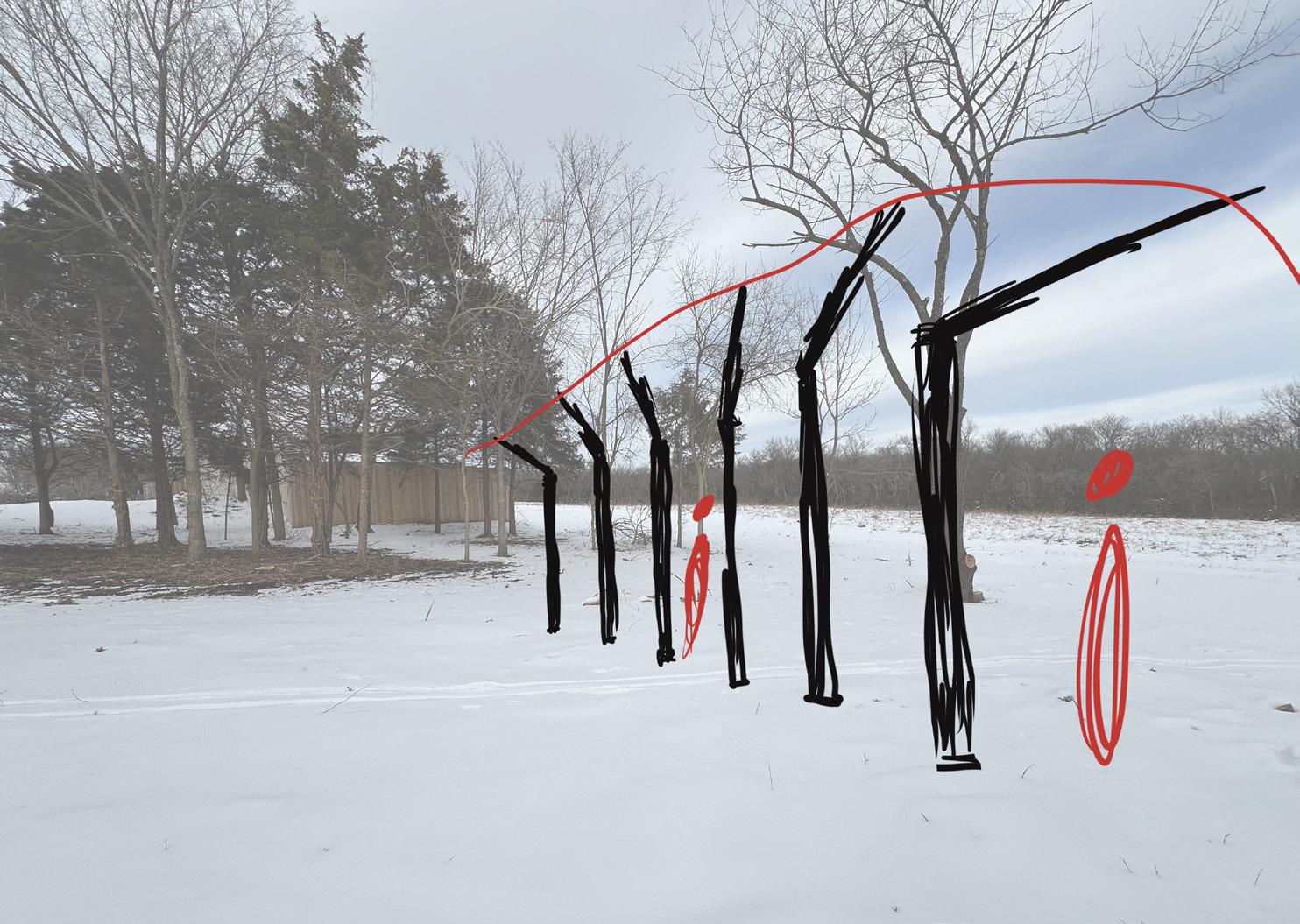
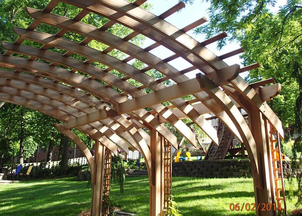
My first idea was the dreaded cantilever. I was drawn to this for a few reasons, mainly for its ability to be completely opened on one side, “opening” towards the prairie. I was also fond of this because of how well its simplicity would blend into landscape, allowing the nature to speak for itself as a compliment to the structure.
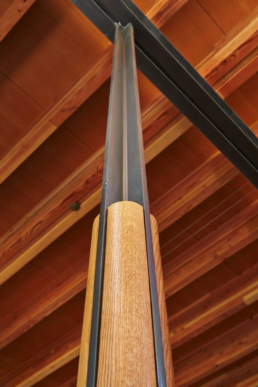
I also wanted to incorporate a unique column design with a cross-section resembling a plus. During our initial visits to the site I came across a plant pictured to the right, and its unique form struck me and inspired me to incorporate it into my concept.
The last idea that I wanted to explore was continuing the existing treeline, helping it to naturally draw the eye into the pavilion.


6 7
Sourced Photo
Sourced Photo
COLLABORATION + COMMUNITY FEEDBACK
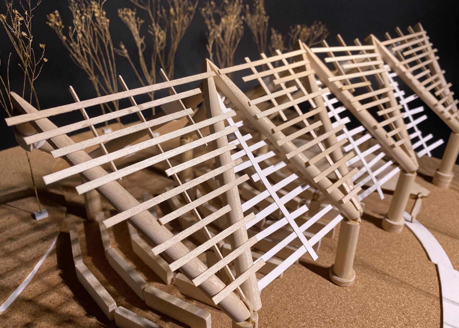

During the collaborative phase, the class was divided into four groups whose ideas were morphed into one. The concept that my group landed on was a “double-cantilever” that was essentially two individual cantilevers that intersected each other at the top. My group mates, Wynn Bowden, Paige Butterfield, and Ashley Decker all assisted in explorations into shading, structure, seating layouts, and more. I focused on a possibility for a connection, as well as cladding and sun shading studies.
All of our groups then presented for public feedback during a forum at the Prairie Park Nature Center, followed by a presentation to the stakeholders where two final designs were chosen. After consulting with structural engineers, my group’s design was chosen to move forward.


8 9
Model crafted by Ashley Decker
FABRICATION + PROCESSING TOURS


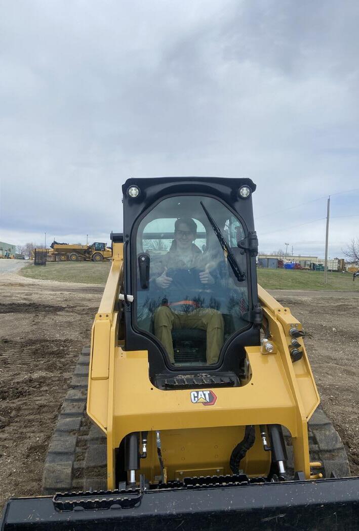
Throughout the semester we were fortunate enough to have the opportunity to tour and experience the plants where our partners worked. It was incredibly eye-opening to see what logistics go into fabrication, especially how an architects drawings can be instrumental in how quickly and easily fabrication drawings can be interpreted. This highlights our duty as designers to streamline processes while minimizing errors which would be costly, especially in environmentally detrimental waste and byproducts caused from unnecessary do-overs.


10 11
2 1
KBS Constructors Midwest Concrete Materials Foley Rental Foley Rental, demo area Haas Metal Engineering AZZ Galvanizing 1 2 3 4 5 6 4 3 5 6
PLANNING + CONSTRUCTION DOCUMENTS

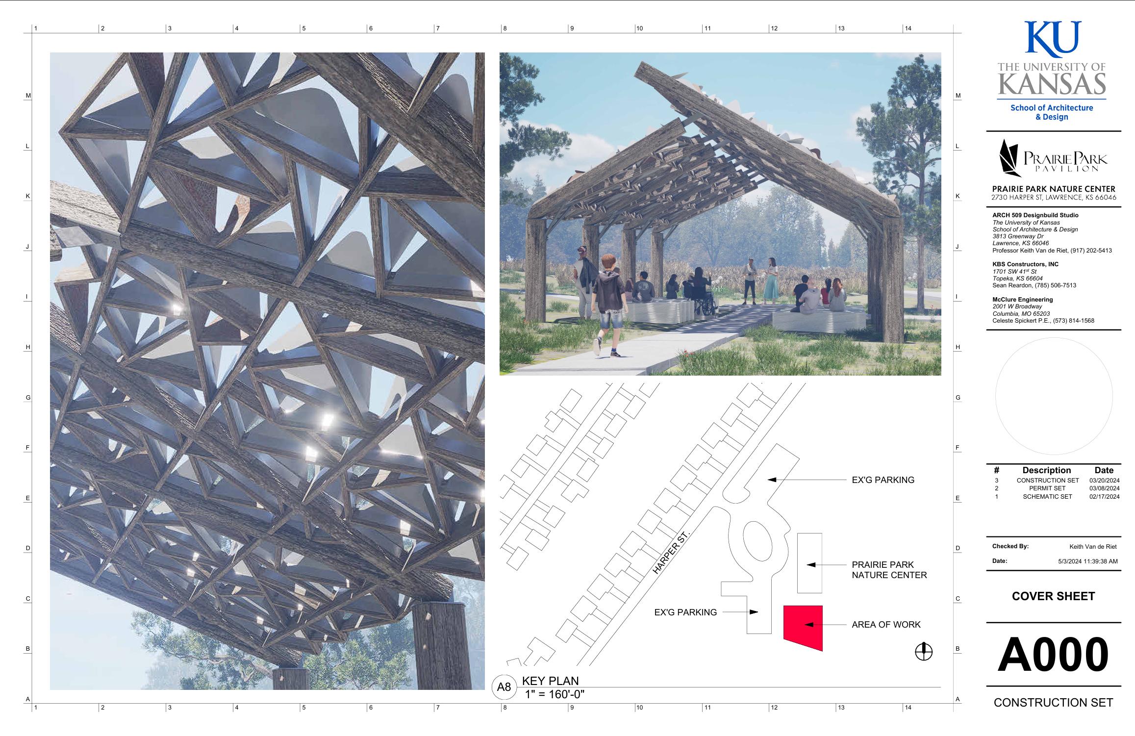

As we started to get into developing the concept into something tangible, I joined and spearheaded the creation of both the construction documents and permitting documents. After sitting in on a pre-submittal meeting with city development staff, I worked with other students as well as the professor to get our permit drawing ready to go as quickly as possibly, including all requirements from the City of Lawrence Planning Office’s checklist for site plan submittals. Other students also had to obtain names and addresses of local residents and mail a notice of development activity.
After the planning documents were sent for review we received minor requests for corrections, which were issued with the week. One of the biggest undertakings for
revisions was calculating the total pervious and impervious area for not only the project area, but the entire lot.
Because of my position spearheading the construction documents, I also set up the shared Revit file and laid out the sheets and title block. I would also end up aiding other students in the creation of their drawings as well as ensuring that all drawings were consistent in style and clarity.
One thing that was quite difficult to stay on top of was making sure that specific items within the construction documents were only called out in one place, as a way to minimize confusion on the job site if an annotation were to change in one place, but have outdated information in another.
12 13

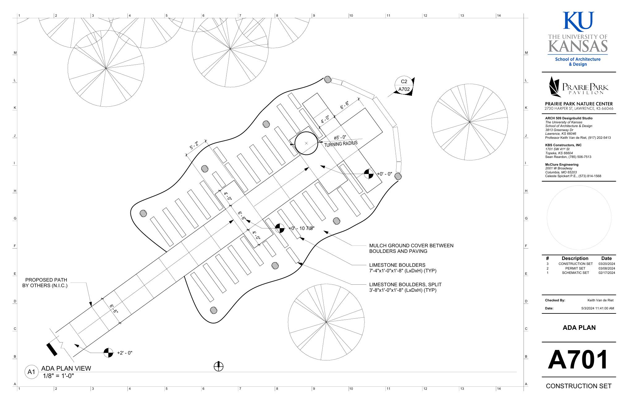
Slope analysis for planning and permitting submittal. Proper grade and rest areas included to satisfy the Americans with Disabilities Act.
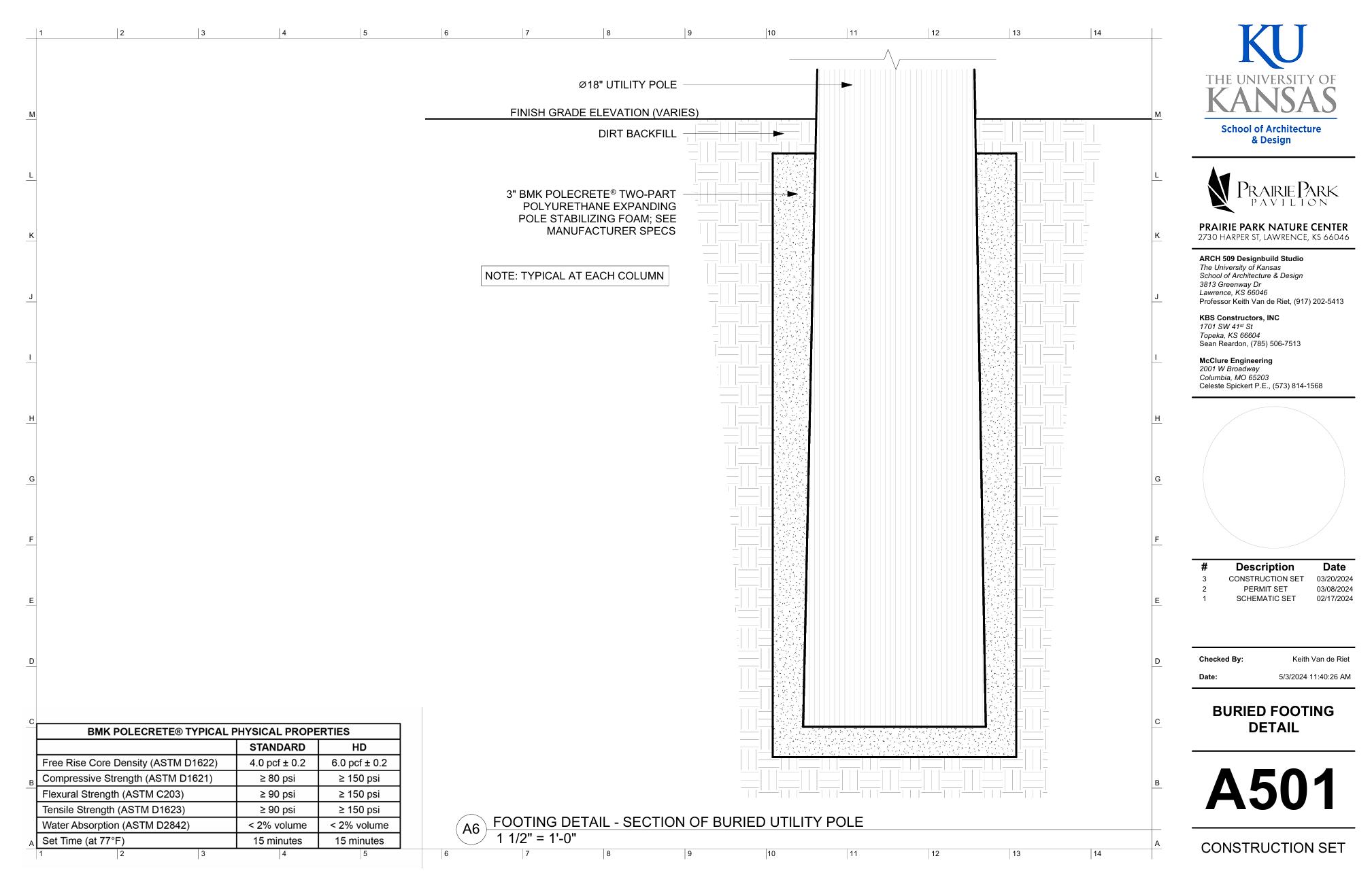
The original footing detail, drawn by Paige Butterfield, went into great depth for if we opted for a traditional concrete footing. Instead we opted to use a more traditional method for utility poles - setting them in an over-drilled and tamped hole and stabilizing them with an expanding structural polyurethane foam called BMK Polecrete.
Accessibility analysis for users with limited mobility. We were sure to include multiple options for those in wheelchairs to sit, both up front and further back, as requested by a community member during a feedback session. These areas can also be used for parents with strollers.
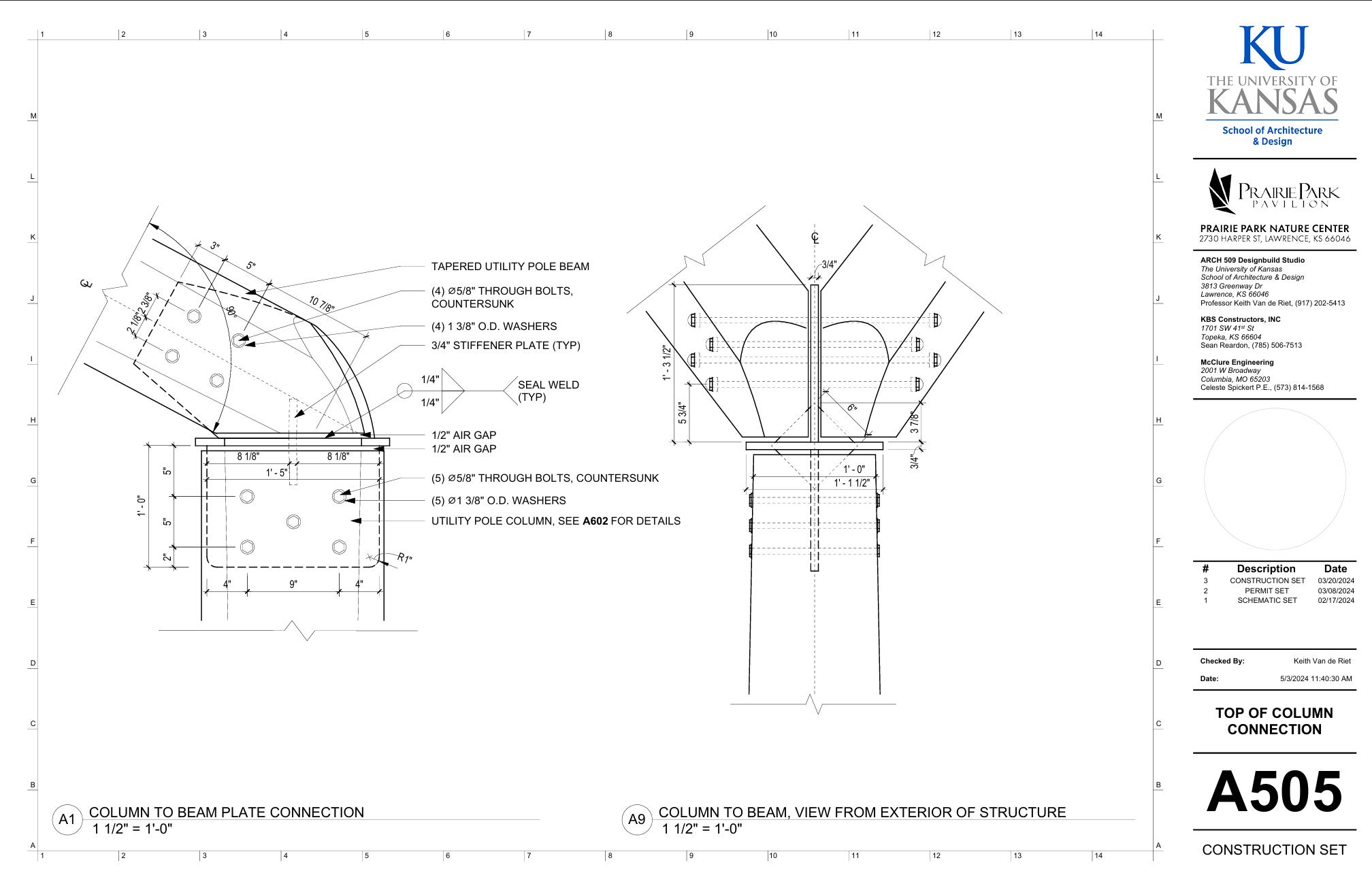
I also drew up the detail drawing for how the custom-fabricated dual knife plate connection would interface with the column and beams, with tolerances and critical dimensions specified and/or verified by the structural engineer.
14 15
SITE LAYOUT
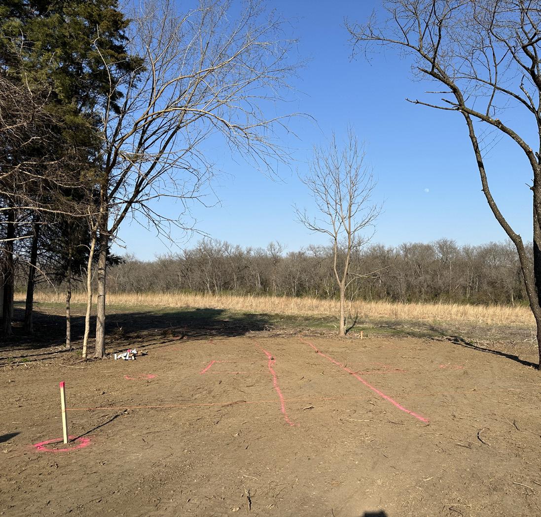
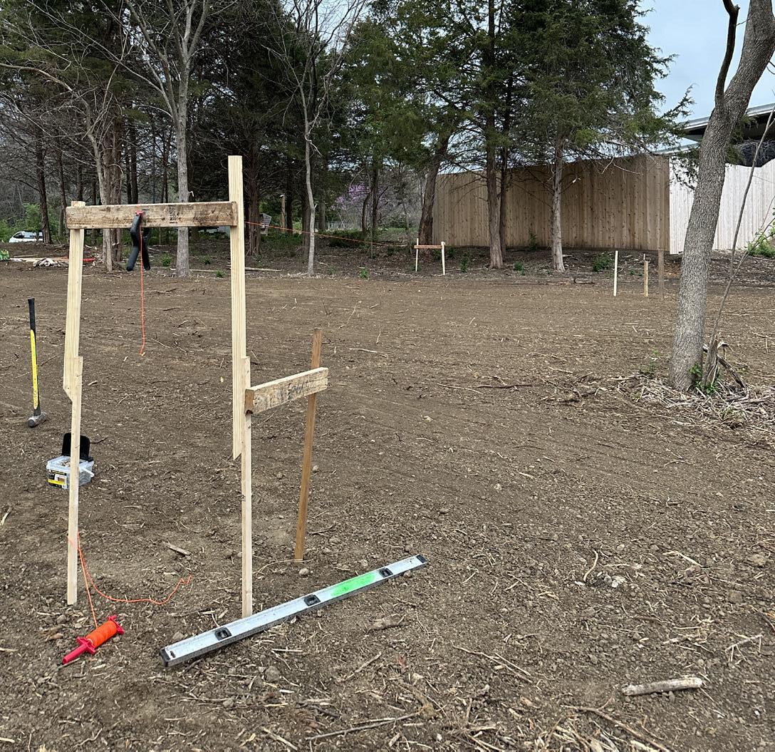

Before moving on-site I generated regrading plans and handed those off to Parks and Recreation, who performed the site regrading on our behalf.
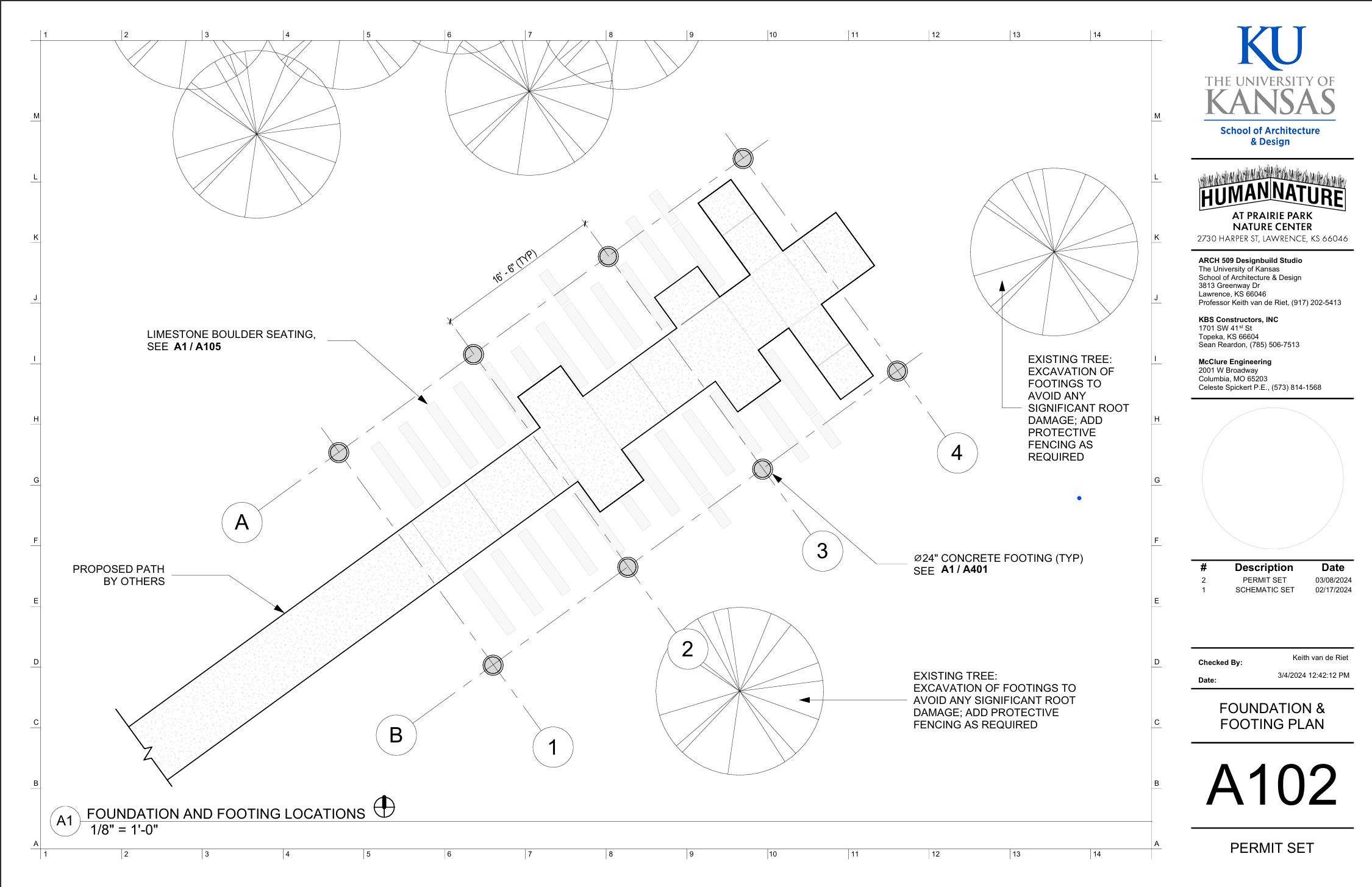
When it came time to move on-site Paige Butterfield and myself carried out the task of laying out all of our locations. We started with rough measurements from two reference points to mark out columns. From those estimations we then set up 12 batter boards and ran string across them. From that we were then able to dial in the final column positions, verifying the dimensions with our construction documents.
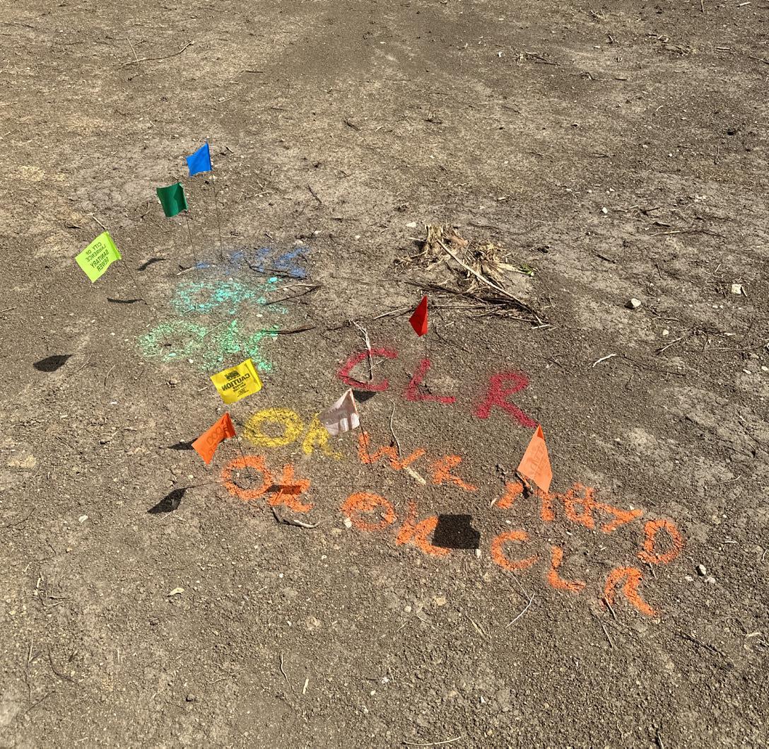
Using the final marks, utility locators cleared all of our footing locations and the next day we had the Evergy team on-site to drill our holes in the ground.

16 17
FABRICATION
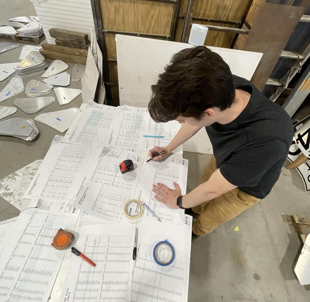


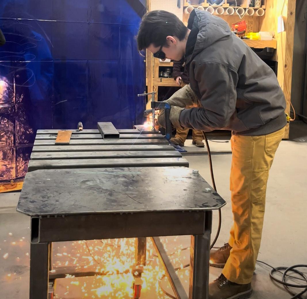
The fabrication phase is where everything started to feel real. In this studio we attempt to do as much as possible in-house. One of my fabrication tasks was to help out the sign crew. I assisted in assembling racks and organizing signs by type, as well as drove a team of us out to the Wamego field office for the Kansas Department of Transportation, which is where we sourced a large portion of our signs. I also assisted in plasma cutting steel elements to weep air during the galvanizing process.
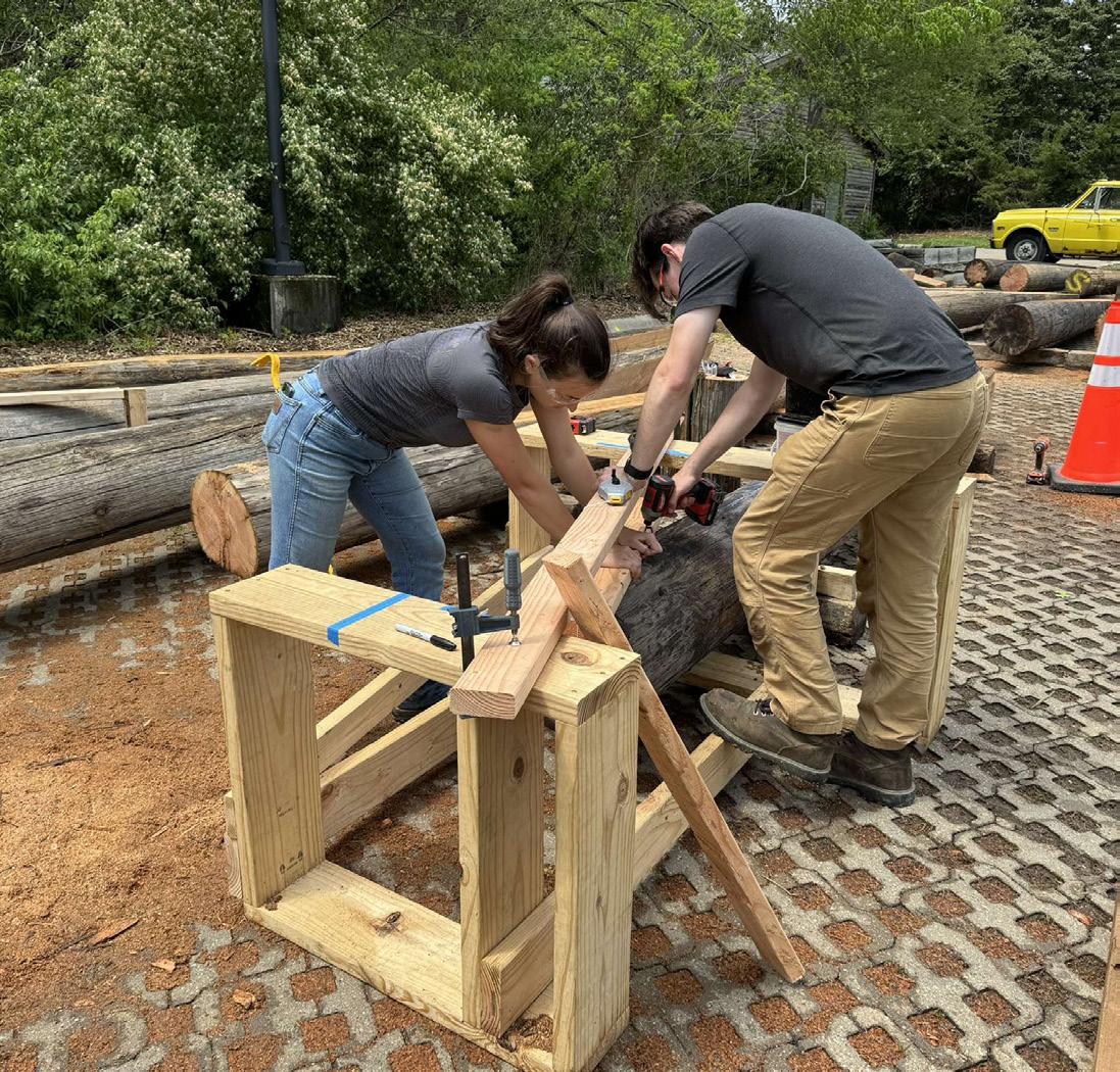
Back on-site, I was getting down to processing our utility poles. This involved setting up a jig around the pole to cut them to length, then another jig for the first cut. From the first cut a third jig was attached, and lastly a fourth jig marked the bolt holes. That entire process was repeated in a bit of a different manner for the tips of the beams the would be receiving a compound knife-place to meet the face of the intersecting beam.
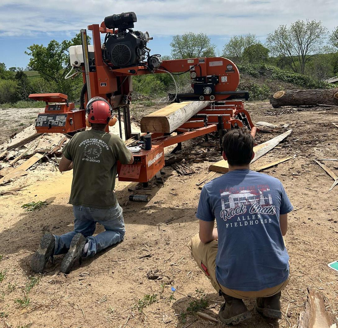
One issue we ran into was integrity of many of our tapered beams. When it came down to it Madison Simons and myself drove our last beam to a local sawmill in Perry, KS to have our final planar cuts performed on a spare beam.
18 19
Marking street signs with unique identifiers Assembling sign storage racks Laying out jig for beam base cut Loading signs at the Wamego KDOT Office Practicing plasma cutting Aligning the blade for our planar cut 1 2 3 4 5 6 1 4 2 5 3 6
CONSTRUCTION + INSTALLATION




Once our permit was issued, we were ready to hit the ground running. Delays with the city meant that after issuance, we only had three weeks to get our project from holes in the ground to photoready for a soft opening ceremony.
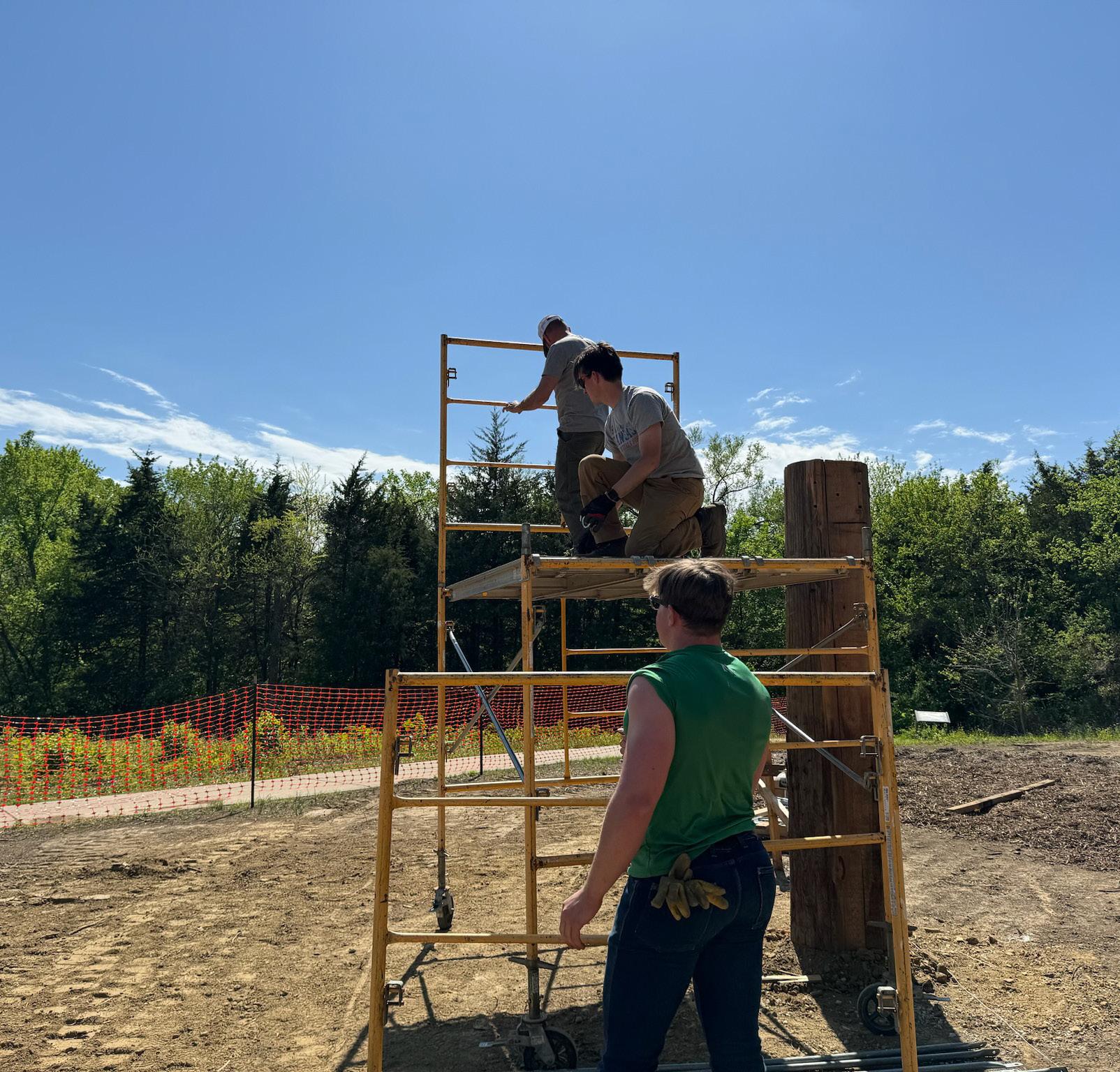
I helped the Evergy crew with placement and alignment of our utility poles, ensuring poles perpendicular to each other matched up and that the poles were plumb. After all poles were set, we erected scaffolding and placed our top plates with the assistance of the telehandler. Now, our poles were ready to receive the beams.
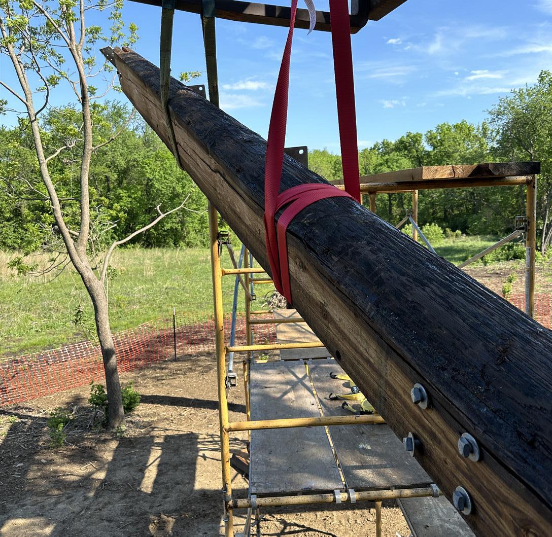
Setting the first beam was easier than we anticipated, however getting the beam to stay in place while we built around it was a bit of a challenge. Thankfully, Cottin’s Hardware donated enough scaffolding that we could lash off the beams to the scaffolding for temporary support.
Once two beams on one side were place, we had to drop the other side in place and land it onto the face of the connecting place and fix it in place with ten lag screws.
20 21
Assisting Evergy with pole placement Assembling scaffolding Installed top-plate connection First beam installation Second beam installation Placing beam onto plate face 1 2 3 4 5 6 1 4 2 5 3 6
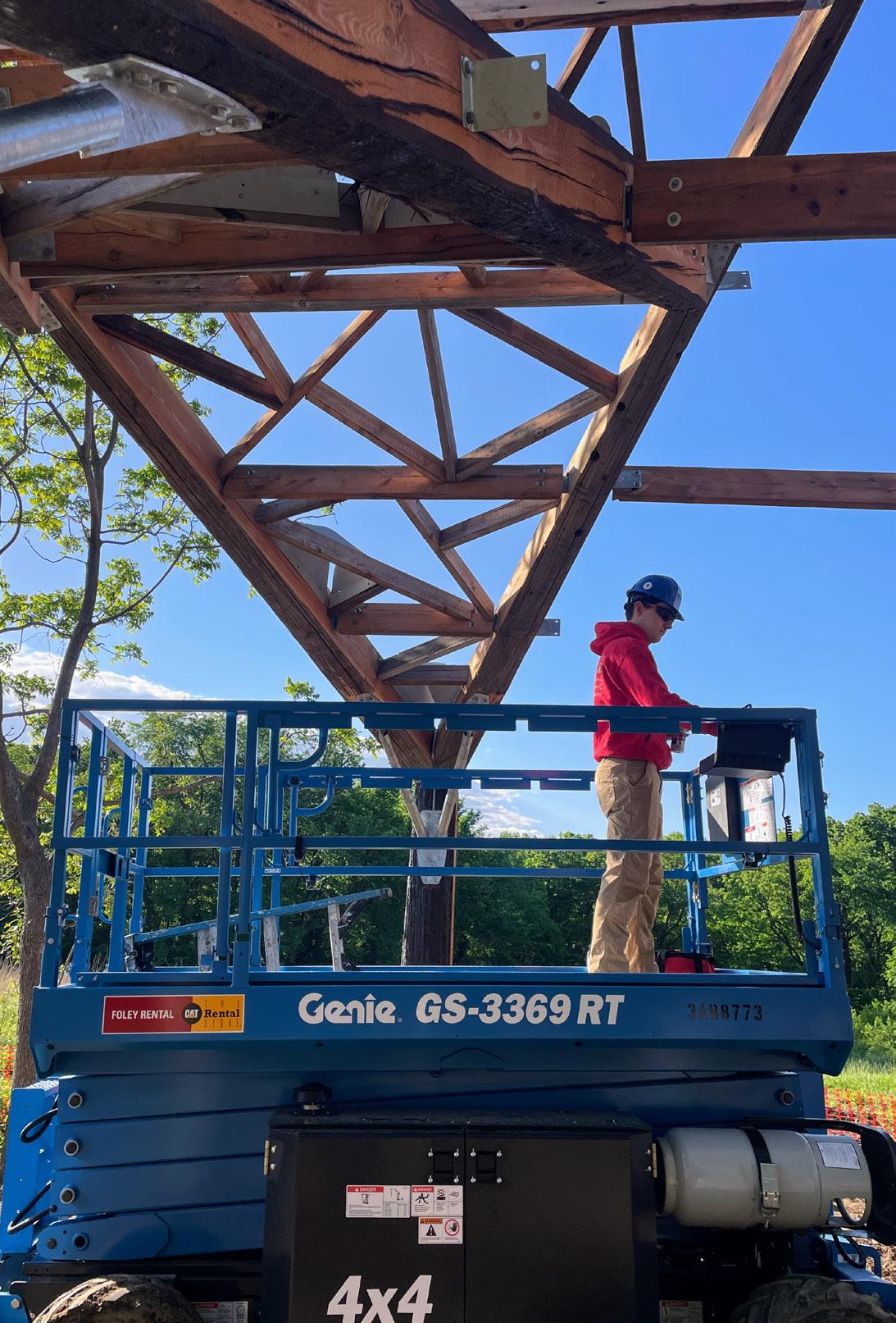

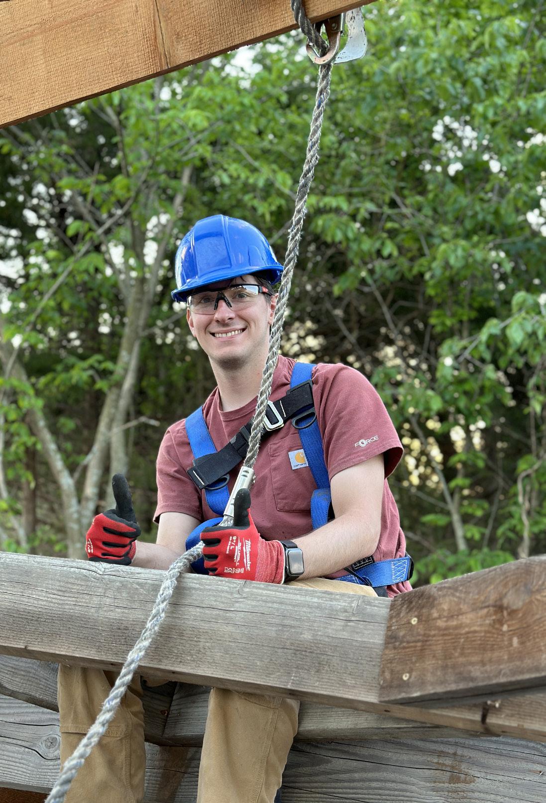
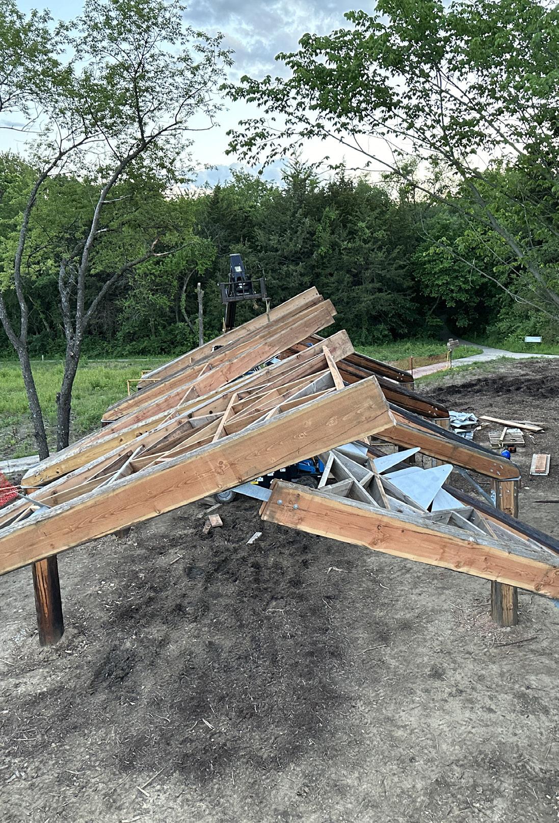
22 23 Driving the Genie lift to the next location for rafter placement Installing infill to the rafters Awaiting the next piece of cut infill View from above the night before our soft opening 1 2 3 4 1 2 3 4
SOFT OPENING


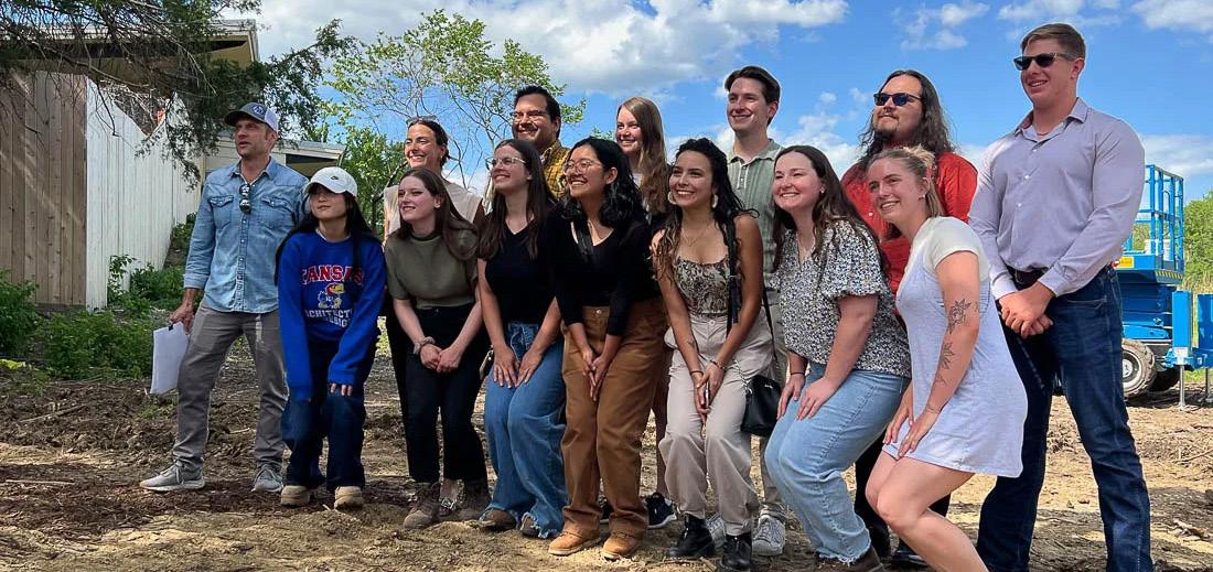
The capstone of the semester was our soft opening ceremony. Family, friends, and members of the community were invited to explore the structure and get a sense for the scale of the near-complete project. At the time of the opening we had one bay nearly complete, with the project in a unique state that showcased almost every stage of construction for our roof.
Prior to the opening I sent some words to Tom Harper from Lawrence Modern regarding the project, which were later shared in the Lawrence Kansas Times. Overall, the community seemed thrilled to see the project coming along and to me, it was the most rewarding part of the project.

24 25
END
26


