LOGPERIODIC ANTENNA THEORY, FREE OF MATHEMATICS
LPDA MATH FREE Scope
Although the logperiodic antenna (LPDA = Log Periodic Dipole Array or log Periodic Dipole Antenna) is a widespread and well-known antenna, there are few information about the principle of operation of these antennas. In classic books of antennas (for university students) the theory is well developed, but it happens that either they are not available to the amateur experimenter or contain mathematical expressions too complex for them
Understanding the operation (even without analytical expressions) allows the experimenter to "know what happens if modifies something ". If you do not know the operation principles, you have no degrees of freedom to act if you find a plane on which you want to experiment and don´t get pipes of the exact size, or want to change the working frequencies, etc. For the telecommunications student, this article will help them to "understand the antenna" before starting a deep theoretical study. It is quite common for a student to be required to explain the theory of something he never saw, and does not know what it is for, or how it works.
With these goals in mind, this article presents a conceptual explanation of how a logperiodic antenna works. As I anticipated a few paragraphs before, making a thorough analysis requires quite complicated mathematics and concepts of transmission lines, making use of Carrell's graphs and other knowledge necessary for a deep and professional study, which will not be addressed here. The objective is that the reader understands the operation and can make a basic sizing of a logperiodic array
Logperiodic Antenna Overview (LPDA)
It consists in a “end fire” array of dipoles (one in front of the other) whose dimensions and separation follow a fixed scale factor.
This type of antenna is characterized by a huge bandwidth (2:1, 3:1 and more) but with a moderate gain (no more than 12 dBi in the real world). In the whole bandwidth not only preserves the impedance, but also the radiation pattern and the gain are constant. This makes them ideal as measuring antennas. It is important to point out that there are other antennas with high bandwidth impedance (such as discone or rhombic antennas), but in these cases the radiation pattern is very different at different frequencies.
Typically, the LPDA has N elements, each element is a dipole, and each of these dipoles is a scaled copy of the previous one, even the separation is scaled to the previous one.
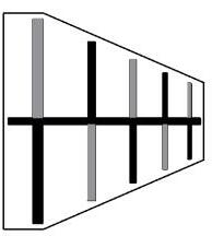
In the market there are LPDA antennas of 1 boom (like the old TV antennas of the late 20th century) and of 2 booms (like the current digital TV antennas in UHF). The principle of operation is the sameas we will see later. There are also LPDA antennas implemented on printed circuit board, in this case they resemble those of two booms. LPDA antennas are feeded from the side of the smaller dipole.
Logperiodic antenna theory, free of mathematics
Ing Martín Lema marzo de 2023
Página 1 de 14
1 Boom 2 Booms PCB
The parts that compose it
In the following photo there is a typical UHF TV reception antenna with the name of the parts that compose it.
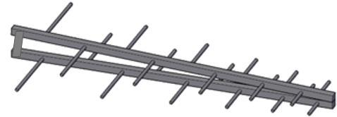
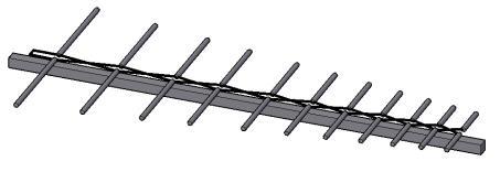
As we will see later, the radiation lobe has its maximum in the direction of the smallest element where the feeding point of the antenna is also located. If connected and fixed from this point, the mast and cable would be in front of the radiation lobe. For that reason, both the fixation and the connection are made on the side of the longer dipoles (the "back" of the antenna).
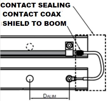
This is solved by passing the cable inside the boom and feeding from the side of the shorter element (see the following photo where the element that presses the cable was removed, for watching where the cable makes contact). The cable passes inside the boom and reaches the back of the antenna where are the connector and the fixing piece to the mast.
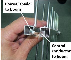
This fixing piece, in addition to being a mechanical reinforcement for a strong fixation, fulfills the function of "stub" that improves the performance in the lowest range of frequencies of use of the antenna and serves to ground the central conductor of the feeder cable. This is done to prevent the formation of high static electricity potentials that would be produced by triboelectric effect if one of the booms were isolated from earth. This effect occurs by the accumulation of charges generated by charged particles blown by the wind.
This antenna was designed in the USA in the mid-twentieth century and is the product of finding a solution to a specific need of that time: an antenna that covers a huge spectrum, with high efficiency and a directional beam.

For starting, a little of antenna theory
An antenna of only one element will always have an omnidirectional pattern, this element can be for example a dipole. No matter how much we experience variants of a dipole, make it shorter or longer, or have a different conductor section, we will get its radiation pattern to be different and its characteristic impedance to be different, but it will always be omnidirectional.
If we want an antenna to be directional, we have only two possible options:
• Put some type of reflective surface near it (such as on a satellite dish, panel, or dihedral antenna)
• Assemble an array or formation with at least 2 elements (as in a logperiodic or other arrays)

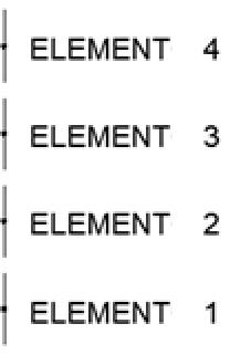
As this article is focused on antennas of the logperiodic type, we will analyze the option of making an antenna directional if it is composed of 2 or more elements (typically much more than two).
All antennas are scalable. If we multiply by a constant K all the dimensions of an antenna that was designed for a certain frequency F, we will have an antenna with exactly the same performance at the frequency F/K. This is an invaluable tool for the experimenter and little spread in the amateur world. This principle applies to all antennas of the standing wave type (Dipoles, monopoles, Yagi, logperiodic, collinear, etc.). These are all the "standard" antennas. For logperiodic antennas this principle is fundamental since each element of a LPDA antenna is a scaled copy of the neighboring element.
Antenna arrays
We already know that, if we have an antenna made of only one element without reflectors or ground plane or anything around it, its radiation pattern will always be omnidirectional. But if we have two or more antenna elements connected to the same equipment we can achieve different radiation patterns, which are even directional (with some configurations, not all). This is what we know as "antenna arrays” or antenna formations. So, for creating an "antenna formation" it is needed at least two antennas, and they must be connected in some way to the equipment This article does not explore into interconnection techniques, the topic of arrays is mentioned only to have some theoretical support when we finally reach the logperiodic antennas.
Logperiodic antenna theory, free of mathematics
Ing Martín Lema marzo de 2023
Página 3 de 14
Broadside formation (one above the other as in an FM station) End fire formation (one in front of the other)The shape of the radiation pattern of an array of N elements has a mathematical expression that I will not bring to this article (I promised not to use complicated mathematics) but, from this expression we can determine that:
• The maximum gain obtainable from the formation will be N times the gain of each element of the formation (in gain times, not in dB). Note: I said the maximum obtainable, not that it always has N times the gain of each element. In the particular case of logperiodic antennas, this criterion applies, but it must be taken into account that N (in the case of logperiods) is not the total number of elements of the antenna, but that of its active zone as we will see later. In addition, the elements are not equal, each dipole is a scaled copy of the immediately preceding one.
• The shape of the radiation pattern depends on the phase with which each element is fed, the distance between elements and their relative position.
• Broadside dipole arrays are always omnidirectional.
• End fire dipole arrays can be directional to one side, or the other depending on the separation and phase with which each dipole is fed. They can also be omnidirectional under certain circumstances.
A simple example of end fire array
Next, we will develop two examples of formation of two dipoles in end fire configuration that is, one in front of the other. As the goal of this article is not to use mathematics, I will not present an analytical solution to both cases (which obviously exists), but I will make a simulation of the two cases seeing what effect phase rotation has on the directivity of the array. In the first case I will connect the two dipoles in a certain way, and in the second case I will invert them (that is, I will add a phase rotation of 180°). In both cases the separation, and all the dimensions of both dipoles remain the same, only changes the way they are fed.
It is observed that the array of dipoles in which the connection was reversed (blue lines) results in more directivity and better front-back relationship, while the other connection seems to be almost omnidirectional and it is difficult to distinguish where is the front or the rear.
This is the reason why in logperiodic antennas this type of connection is used, always each dipole is connected "reversed" with respect to the immediately previous. This results in a directional antenna with a well-defined front side.

Logperiodic antenna theory, free of mathematics
Ing Martín Lema marzo de 2023Página 4 de 14
About how was arrived to the logperiodic array
Starting from the following premises, we have the necessary tools to understand why a LPDA is directional, has gain and enormous bandwidths.
Premises:
• A dipole has a resonant frequency that depends on its length.
• All the antennas are scalable.
• Dipole arrays can be assembled to obtain a directional pattern
• Conductors radiate mainly through discontinuities. For example, a flat plate (such as a patch antenna) radiates more of the power around the edges of the board.
I believe that the best way to "understand" how a LPDA antenna structure works, is following all the stages of its development in the same order. In fact, even for a thorough analytical study it is much easier if you first "understand" the structure, there the electromagnetic phenomena that are applied and their associated mathematical expressions take on a more tangible meaning.
What was the original objective of the development of such structures? The objective was looking for an antenna that works in the same way in all frequencies, that is, an antenna independent of the frequency. It is well known that this is impossible. Then it was always kept in mind that infinite bandwidth doesn´t exist, but at least it should work on a huge region of spectrum.
There comes the first inspiring question: if antennas have a resonant frequency proportional to their length, how to make an antenna resonant at any frequency?
The answer is simple from the theoretical point of view, but directly impossible to implement in practice. This answer is: the shape of the antenna should not be defined at any point by its dimensions (lengths). And, if it is not defined by lengths, what would define the antenna?
Angles, a structure whose shape is only defined by angles could be used to implement an antenna with infinite bandwidth (or at least very large, since we said at the beginning that the word “infinite” doesn´t exist in engineering).
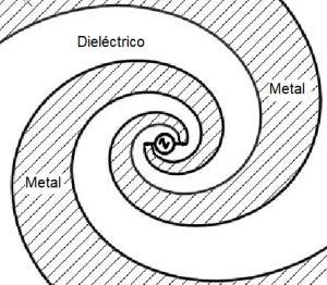
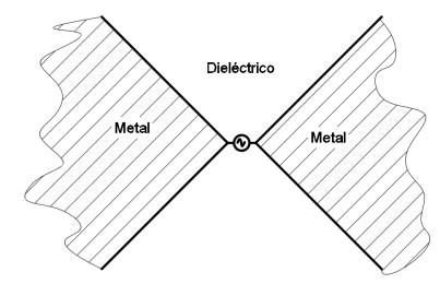
While there are several geometric shapes defined only by angles, there are two that are important in the history of the development of logperiodic antennas. In fact, they are the two simplest: two triangles faced by the vertex (the simplest) and the equiangular spiral (a little more complicated).
Logperiodic antenna theory, free of mathematics
Ing Martín Lema marzo de 2023
Página 5 de 14
Flat antenna implemented with two triangles facing each other. Flat antenna implemented with equiangular spiral. In the figures above, the generator symbol represents the feed point of the antennas.But it happens that, for obtaining an infinite bandwidth, both the triangles and the spiral must be infinite. If the structure is truncated, it is not more independent of the frequency since they were truncated at some point and a measurable length appears (and reflections-VSWR- appears).
A possible practical solution is to truncate it far enough from the origin, although it is not infinite, it is too large that it seems to be infinite. So, with two facing triangles or an equiangular spiral, it is possible to have antennas that at least in a certain range works the same way at all frequencies. Both configurations are possible to be built, and work correctly as frequency-independent antennas, but they have a drawback. For them to "seem as infinite" they must be truncated to several wavelengths. This means that, although they are implementable in UHF, worse in VHF and much worse in HF makes these structures really freak. The triangles are simple, but huge. Spirals can be truncated into smaller dimensions, but they are still too large.
Then, the second inspiring question appears: How do you make a small structure "feel" like it is infinite, or at least bigger than it really is?
The answer is that we must not forget that we are talking about antennas, so all that part of the structure of the antenna that doesn´t radiate anything, is the same whether it is or is not. So, if we make the structure radiate a lot very close to the origin, as the energy moves from the origin to the end, if it is truncated, there is no longer enough energy for the antenna to "feel like it's truncated" because it already radiated almost all the power. If energy doesn´t reach the truncated zone, it cannot reflect anything, and there will be no VSWR
How can be achieved this of radiating very close to the origin?
We know that structures radiate mainly by discontinuities, so, if for example, we add discontinuities (i.e. edges) to the facing triangles, surely more energy radiates from those edges and reaches less to the area where they are truncated. That idea sounds good, but, if cuts are added anywhere, those cuts will have a certain measure and therefore the concept of "structure defined only by angles" is lost and will be frequency dependent.
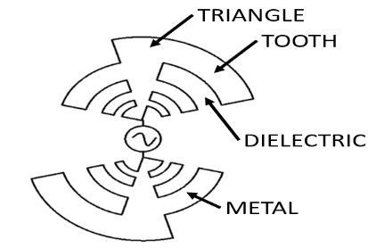
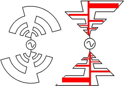
Here appears the "crazy idea" that is “the mother” of modern LPDA: We know that two opposite triangles make up a good antenna independent of frequency, but two triangles have few edges (discontinuities) and therefore must be very large for the antenna to feel infinite. We also know that the spiral in the same area has more edges than triangles but is more difficult to implement. What would happen if we mixed triangles with spirals? One thing is certain, if both structures are defined only by angles, the result of combining both will also be defined by angles (a necessary condition to be independent of frequency) and will have a much larger perimeter (more edges and therefore more discontinuities).
This "crazy idea" was implemented and worked fine, resulting in a relatively short antenna, usable in practice and independent of frequency at least in a large range Here arises the "toothed antenna" (self complementary toothed structure). This is the first frequencyindependent antenna, of reasonable size and implementable in practice, although it will be necessary a little more steps for becoming the current LPDA. Toothed: is quite obvious why that name. Self-complementary is because a plane figure is said to be self-complementary when the metal and dielectric surfaces are the same and have the same shape. Note from the up image of the toothed antenna that if we
Logperiodic antenna theory, free of mathematics
Ing
MartínLema marzo de 2023
Página 6 de 14
"fold" it in the center vertically, the metal part on the right fills the dielectric parts on the left. And if we "fold" through the center horizontally, the underside of metal fills the top with dielectric (this horizontal folding will be very important in the next stage to reach the actual design.
This toothed structure is feasible, although in practice some simplifications were made that, although they subtracted some benefits, greatly simplified the practical construction. The first modification was to straighten the teeth, in the original design they are curved (since they follow the equiangular spiral). The second "simplification" is not to do it with sheet of metal but with pipes, those of the smaller teeth with thinner pipes and those of the larger teeth with thicker pipes. When analyzing or running a simulation of this simplified structure, it is observed that the resulting radiation pattern tends to be omnidirectional and quite uneven depending on frequency.
Both things have logic, both the triangles and the spiral have an omnidirectional pattern, and the uneven performance is due to the simplifications made that move the built structure quite far from the ideal theoretical configuration.
How do we make this structure directional?
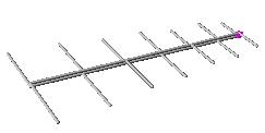
We observe that, if we fold this structure by the center, it results in a configuration very similar to the directional dipole formation that we analyzed at the beginning of this article and is the configuration of a actual two-boom LPDA antenna.
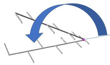
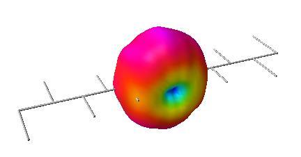
We fold the structure by the feeding point Final configuration
In the graph below the connection of the first two dipoles is shown with a lot of zoom, the rest is the same. It is clearly observed that the "dipole 2" is connected "backwards" than 1, then 3 backwards than two and so on until the last element. In this way a structure is assembled that is strongly directional, and independent of frequency (at least in the operating range).
Logperiodic antenna theory, free of mathematics
Ing Martín Lema marzo de 2023
Página 7 de 14
Sizing a LPDA antenna
The design of a logperiodic antenna is really complicated, it requires Carrell graphs, quite advanced mathematical expressions, especially for the calculation and dimensioning of the transmission line that joins each dipole with the neighbor. In 2-boom antennas, this line is formed with the same booms. In single-boom antennas, it must be performed with conductors.

But, despite the above, there are some simple guidelines that can be followed for a basic dimensioning that are useful and implementable.
The usable frequency range
The usable frequency range of the antenna is fixed by the end elements, the longest dipole determines the lowest frequency, and the shortest dipole determines the highest frequency. A "rule of thumb" is that the longest dipole is λ/2 of the minimum frequency (sometimes a little longer to give a little margin of error to the assembly, sometimes 10% higher) and the smallest dipole will always be shorter than λ/2 of the maximum frequency. With this criterion it is possible to get an antenna that may be a little oversized, but we are sure that it will work well in the desired range. As we said before, a thorough design requires a lot of work, however with this simple criterion, it is possible to obtain a functional antenna
 Ing Martín Lema marzo de 2023
The gain, the number of elements and the separation between them
Common sense tells us that the number of elements has relationship with antenna gain, that is, more elements more gain. And the more elements, the longer the antenna. From analyzing the curves that are used for the design of these antennas (Carrell curves), it emerges that there are numerous different combinations with antennas with more or less elements, with greater or lesser flatness of response, optimized in gain, or in length, etc.
The actual gain obtainable with a logperiod antenna is moderate, typically between 8 dBi and 12 dBi. This is because, in most real configurations, only some of the dipoles are close to the resonance and emit the most energy, the rest have little influence. This is what is called "the active zone of the antenna". At the low frequencies of the operating range, this zone is near the longer dipoles, at the center frequencies in the middle of the antenna, and at the higher frequencies near the smaller dipoles.
For this article and as the objective is not to use complicated mathematical expressions, a simple solution is presented, in the form of a table, which determines the separation and scaling of each dipole depending on the desired gain. This table arises from selecting the "optimal points" of the Carrell curves. The most curious reader can google these curves. The table is presented for 2:1 and 3:1 bandwidth. A 3-to-1 is an antenna operative between 100 and 300 MHz for example
It should be noted that the value of σ (sigma) presented here is twice that obtained from the graph of the Carrell curves (for those who have googled the curves). This is because using the complete method (with all its formulas), the value of σ is used in several expressions. One of these expressions is the calculation of the separation between elements, which turns out to be 2σ. As, in this article it is only used for separation, twice the value obtained from the original graphs is shown directly in the table.
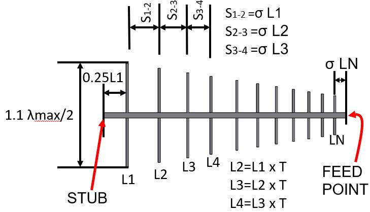
The table of separations and scaling Vs gain is shown on the right in which T (Tau) is the scale factor between dipoles, and σ (sigma) is the scale factor of the separation. For each dipole, the next smallest will have length T (Tau) times its length. Regarding separation, the criterion is that given a dipole, the next smallest will be separated by a distance σ (Sigma) times its length.

N for 2:1 means the number of N elements needed to obtain the desired gain with a bandwidth of 2:1. The 3:1 column uses the same criteria but for a bandwidth of 3 to 1.
Logperiodic antenna theory, free of mathematics
Ing Martín Lema marzo de 2023Página 9 de 14
Example:
The best way to understand the above table and the meaning of T and σ is through a real case.
Consider designing a log-periodic antenna for UHF TV that covers the 470 MHz to 803 MHz band and has a gain of 8.9 dBi.
The bandwidth is 803/470 = 1.7, it approaches 2:1, so the number of elements for a gain of 8.9 dBi with bandwidth of 2:1, is 10. Using the right formulas and the Carrell plot, it is possible that this number can be optimized, but not much, probably results 9. But remember that this method is approximate. There are also many applications available on the Internet for LPDA calculation, although it is always prudent to compare the results of the applications, if the values obtained are too different there may be some kind of error in the use of the applications.
We first calculate the dimensions of the longest dipole and assume a 10% margin of safety.
For the longest, λ (470 MHz)=300/470=0.64m
As the dipole must be 1.1 x λ/2 it results from 1.1 x 0.64 / 2 = 0.352 m
We round to 35 cm that is 0.35 m.
Logperiodic antenna theory, free of mathematics
Ing Martín Lema marzo de 2023
Página 10 de 14
From the table, for a gain of 8.9 dBi we get T=0.86 and σ=0.32
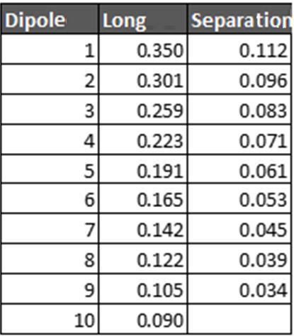
Then the longest dipole will be 35 cm
The separation from the first to the second will be 35cm x 0.32 = 11.2 cm
The length of the second dipole will be 35cm x 0.86 = 30.1 cm
The separation between the second and third will be 30.1 x 0.32 = 9.6 cm
The length of the third dipole shall be 30.1 cm x 0.86 = 25.9 cm
And so on until the tenth.
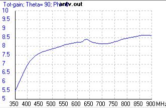
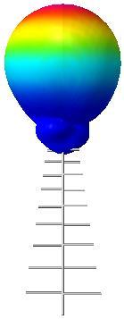
Only as a verification, was simulated the antenna calculated above with 4NEC2 obtaining results very similar to those wanted. The graphs below show the results of a simulation with all elements of 6 mm diameter without optimizing anything.
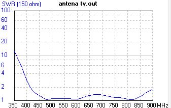
VSWR (for 150Ω impedance) Gain in dBi
The impedance of logperiodic antennas
So far, everything written refers to dimensions (length of the elements and separation between them), there was no talk of the impedance presented by the set. If the antenna were built with very thin conductors (especially booms) the impedance presented at the power point is of the order between 100 and 150 Ω. To reach the 75Ω that is want in TV or the 50 Ω typical of radio systems, in general it requires much thicker conductors, in particular those of the boom in the antennas of 2 booms.
The impedance presented by the assembly is strongly influenced by:
• The average impedance of the shortest dipole
• The impedance of the transmission line
Both require very complicated mathematical expressions that are far beyond the scope of this article. But we can affirm that the impedance of the smaller dipole is governed practically by its diameter (the larger the diameter, the lower the impedance), while those of the boom mainly by the separation and the surface that each branch of the boom presents facing the other branch. The closer and more area the boom has, the lower the impedance. For that reason, the booms of square section and very close to each other are usually implemented.
Sumarizing:To calculate analytically the impedance presented by a LPDA antenna, a huge set of mathematical tools are needed, especially of transmission lines, which far exceeds the object of this article. For the experimenter (whether assembling the antenna
Logperiodic antenna theory, free of mathematics
 Ing Martín Lema marzo de 2023
Página 11 de 14
physically or in electromagnetic simulators) must take into account that larger booms or closer to each other lowers the impedance of the whole assembly.
The three zones of logperiodic antennas
LPDA antennas has 3 zones with different functions.
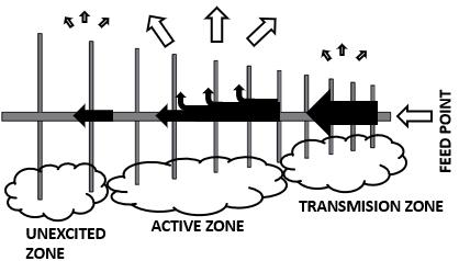
• Transmission zone
• Active or radiation zone
• Unexcited area
The active zone will be closer to the smaller dipole at high frequencies enlarging the unexcited zone. And at lower frequencies, the unexcited zone will be smaller and the transmission zone longer.
At the active zone the dipoles have lengths close to λ/2 so they radiate most of the energy, and little reaches the unexcited zone (hence its name). In the transmission zone the dipoles are too short to be efficient radiators and therefore behaves more as a transmission line than as a radiator. In general, the active zone involves several dipoles, but not many. This is the reason for the minimum and maximum gains achievable with a real log-periodic antenna.
The diameter of the dipoles, the stub and the feeding point
The diameter of the dipoles should be scaled with the same scale factor as the dipoles (T), in general this is not done in TV or amateur antennas. The same diameter is usually used for all dipoles. While the performance is not optimal for doing this, the practical benefits far outweigh the quality limitations that come with it. Only in some precision antennas (such as those used for measurements) the scaling of diameters is applied (but this article does not point to that type of antennas).
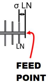
The feeding point arises from simulation-based experimentation. A reasonable starting point is to assume that the feeding point is at the distance that would correspond to the next dipole if it existed.
Regarding the stub, its function is to improve the performance of the antenna especially the impedance value in the zone of lower operating frequencies (when the active zone is near the largest dipoles). At high frequencies and from the center of the bandwidth of the antenna has almost no function at the RF level. Like the feed point, the exact position emerges from simulation tests. But considering that a quarter of the total length is separated from the longest dipole is a good starting point.
Logperiodic antenna theory, free of mathematics
Ing Martín Lema marzo de 2023Página 12 de 14
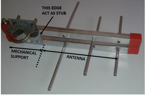
It is also an important part, since it shortcircuits the central conductor to earth and prevents the formation of electrostatic charges by triboelectric effect. The image on the right shows a small logperiodic antenna. Up to the edge of the stub is the "antenna" part. From that edge to the left there is no RF circulation, so it is not part of the antenna and its dimensions and shape only serve mechanical support function.
The LPDA of a single boom
These antennas were very common in VHF TV antennas of the mid to late twentieth century. Today they are rarely found as commercial antennas since they have many connections, need insulators, etc. To explain the operation and its dimensioning, applies all the criteria expressed in this article.
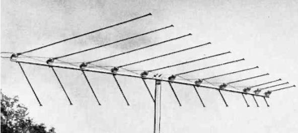
The only difference is the transmission line that is materialized with two conductors passing from one side to the other and the stub that consists of a stretch of transmission line. All the dimensions and functions of the elements are the same as those of two booms.
Another reasonforthe use ofthis configuration inVHF is that the antenna is large enough to be fixed at one end. It is fixed from the center. A two-boom antenna fixed from the center would require isolators to prevent the mast from short-circuiting the two booms.
Why are the booms slightly angled in the 2 booms?
Recalling the premise that each dipole is a scaled copy of the previous one, and all its dimensions must be scaled, including the separation between the two branches of each dipole. That is why the centers of the larger ones must be more separated than the smaller ones. This is solved by putting the booms with a certain angle to each other (on the side of the larger dipoles farther apart than on the side of the smaller ones). In general, an angle of 5° or 10° is sufficient for acceptable operation in practice.
Why are they called logperiodic?
The purpose of this article is to explain the operation with the least possible use of mathematics, but to explain the name "logperiodic" there is no choice but to use logarithms. This paragraph has no practical application in the explanation of operation but serves to justify the name of the antenna.
They are so called because the logarithm of the length of the elements follows a sequence that varies periodically with the logarithm of the scale factor T. In the previous example it was determined that for the gain to be obtained, a scale coefficient (T) of 0.86 was established.
Logperiodic antenna theory, free of mathematics
Ing Martín Lema marzo de 2023
Página 13 de 14
The logarithm of 0.86 is -0.066. The longest element is 35 cm i.e. 0.35 m, the logarithm of 0.35 turns out to be -0.456. If we add the logarithm of the scale factor, we get the logarithm of the length of the next element. To obtain the logarithm of the one that follows, we simply add the logarithm of the scale factor again. And so on to the last element.
Since the resonance frequency of each dipole is related to its length (λ/2) and we know that the logarithm of the length of each element follows the sequence seen above, the resonance frequencies will do the same. Then the resonance frequencies of each dipole will follow the same pattern of repetition (on a logarithmic scale) that is repeated periodically with the logarithm of the scale factor. Hence its name: LPDA (Log Periodic Dipole Array or sometimes Log Periodic Dipole Antenna).
Logperiodic antenna theory, free of mathematics
Ing
MartínLema marzo de 2023
Página 14 de 14
