
INTERNSHIP PORTFOLIO

1 SEPTEMBER 2023 | ARCHITECTURE | 2023
Welcome to my September 2023 Portfolio : )
The projects below illustrate a wide scope of assignments issuded by the university of Cape Town (EX01-06) and two projects I worked on as a part-time employee at a Architectural Firm in Cape Town (EX07) and as a freelance designer (EX08).
Thank you for taking the time to look through. Cheers !
Regards
Lionel Moss Concept Drawings p3 Diagrams & Site p2 Final Drawings p4
PROJECT X PART-TIME WORK HS Architects
2
INDEX
01
05
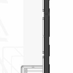
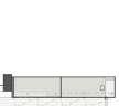
1:10 Sectional
02 TECHNICAL
Apartment
Final
Water
Glazing
06
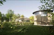
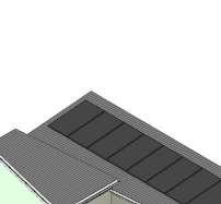
CLIMATE SHELTER Concept p24 Unit Layout p25 Structural Exploration p26
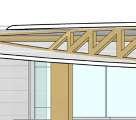
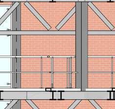
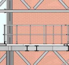
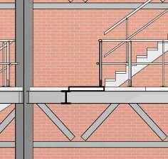
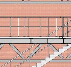
STEEL FRAMEWORK 1:20 Technical Section p7 1:10 Design Details p8
Model p8
DEVELOPMENT Climatic research p34
Orban, NYC p40 Concept Drawings p35 As Built Drawings &
Drawings p36
& Power analysis p37
& fenestration p37 Proposed intervention
Atmospheric sketches p10 Concept development p11
03 SACRED
07 08 CONSTRUCTED
04 SECTIONAL
0.0
Cutting Models P12 Concept Sketches p13 Drawings & Renders p14
SPACE MooiMED Sign p41 MooiMED Smoke area p41
PROJECTS Structural exploration p16 Detail Design Sketches p17 Sectional Models p18 Final drawings p19 Final Sectional Model p22
DEVELOPMENT
Final Drawings p28 Renders p32
PROPOSAL DATA
TYPE: Conceptual design
DATE: 27 February - 24 March 2023
LOCATION Elands Bay, Western Cape
PROFESSOR Tomà Berlanda
COLLABORATORS Clint Abrahams
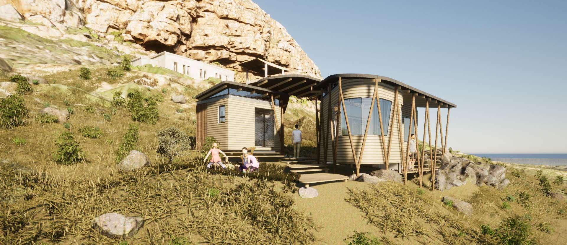
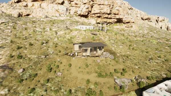
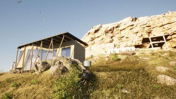
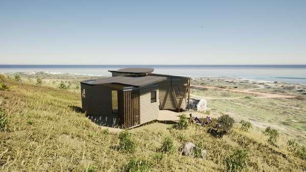
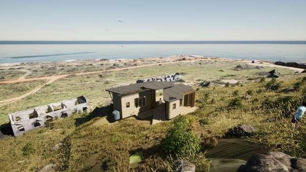
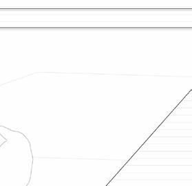
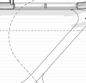
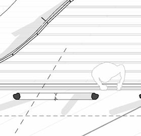
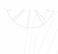
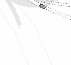
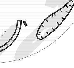
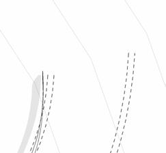
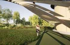
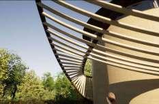
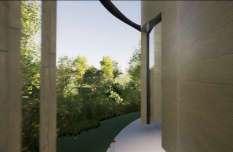
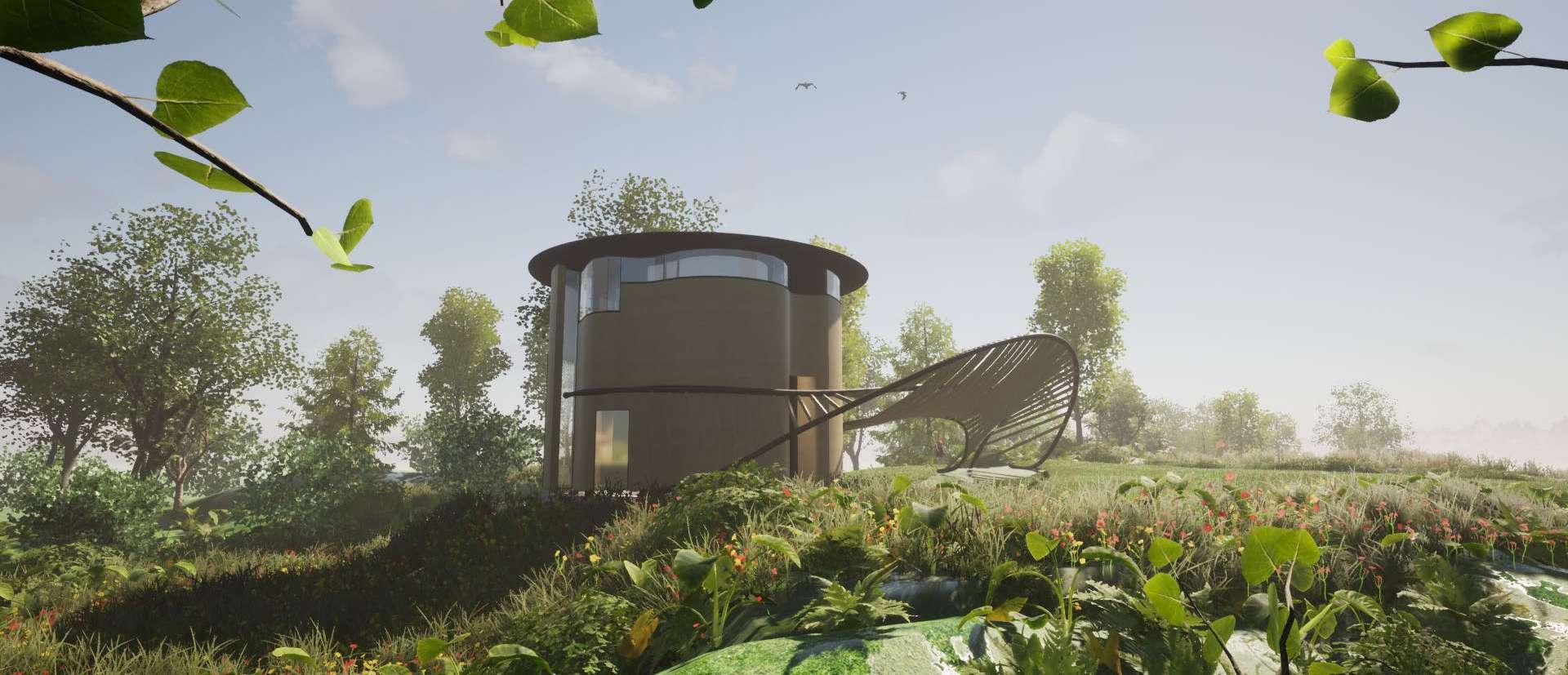
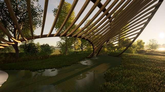
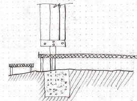
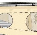
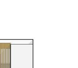
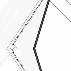
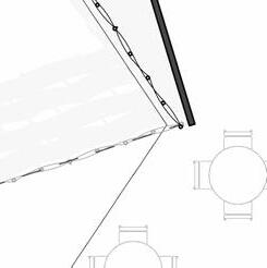
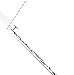
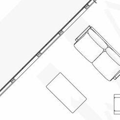
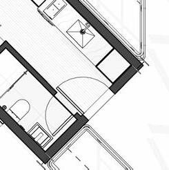
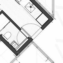
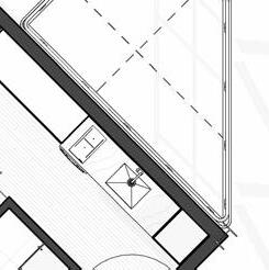
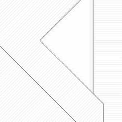
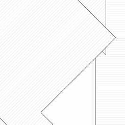
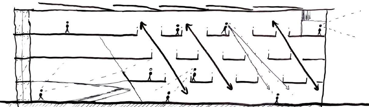
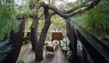
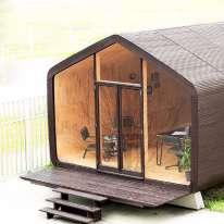
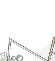
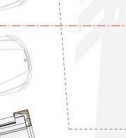
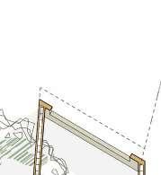
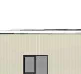
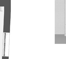
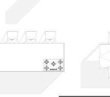
A shelter is a place of rest where those inside feel protected. The classic hiker has three basic wants from an overnight hike experience. He wants a place to sleep, eat and enjoy the view. We are achieving this by creating a public, semi-private and private space.
Hikers have an appreciation for nature. A hiker’s motto is “Leave no trace.” Therefore, we aim to create a structure that touches the ground lightly with little disturbance to nature.
We want to encourage a specific approach to the building where the hiker can experience the vertical view of the mountain framed by the shelter. The paths between the two parts of the shelter allow undisrupted movement for hikers who decide not to rest while exploring the mountain.
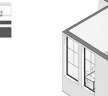
3
0.1
CLIMATE SHELTER
Concept Drawings

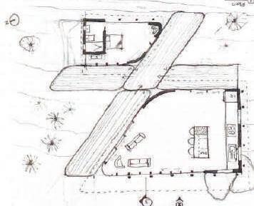
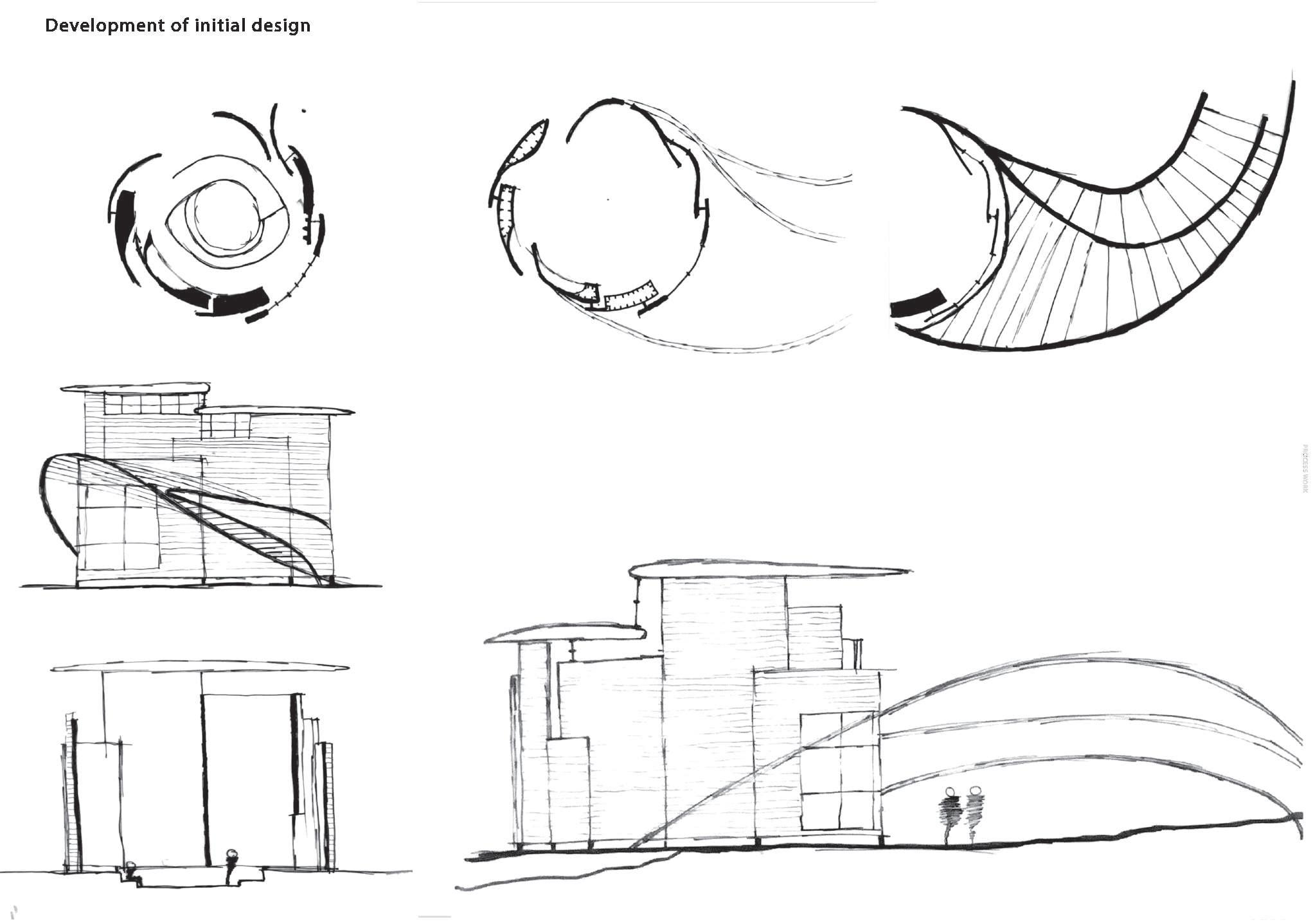
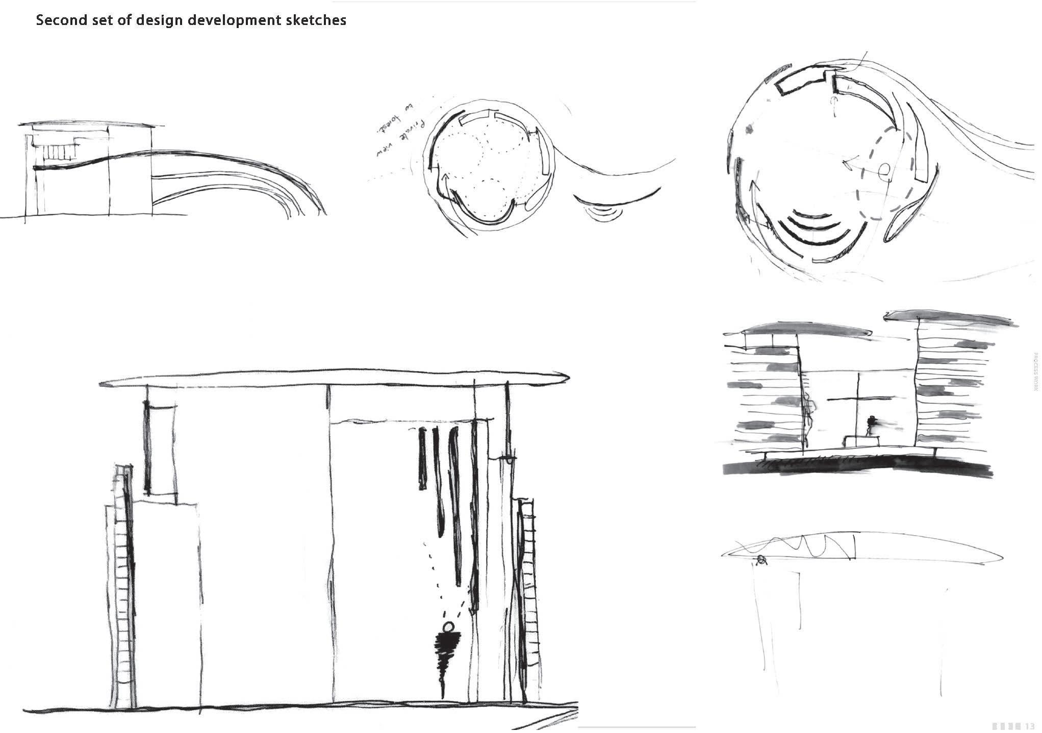
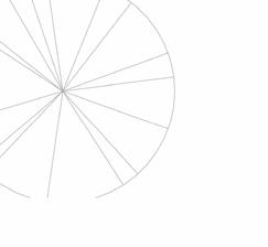
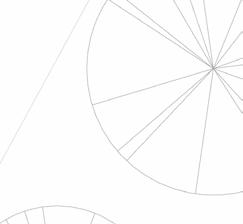
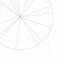
4 PLAN CONCEPT DRAWINGS 0.1 15
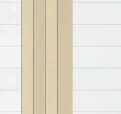
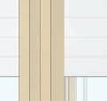
EX 02 CL IMA TE SH EL TE R- CO NC EP TD RA WI NG S NO AC AS TR OL ION EL MO SS KA TE HA LLE EX 02 CL IMA TE SH EL TE R- CO NC EP TD RA WI NG S NO AC AS TR OL ION EL MO SS KA TE HA LLE Concept Drawings
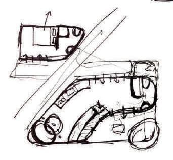
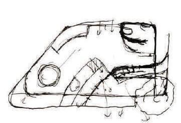
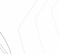
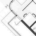
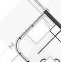
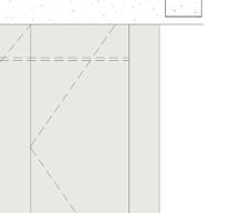
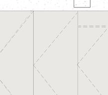
Exploration of basic forms from Simple rectangular layouts to the final shape as seen in plan
Spacial exploration within the decide floor plan form.
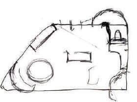
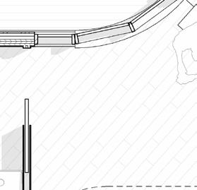
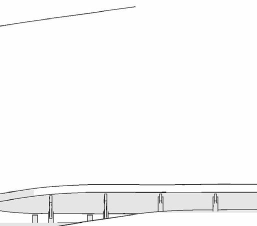
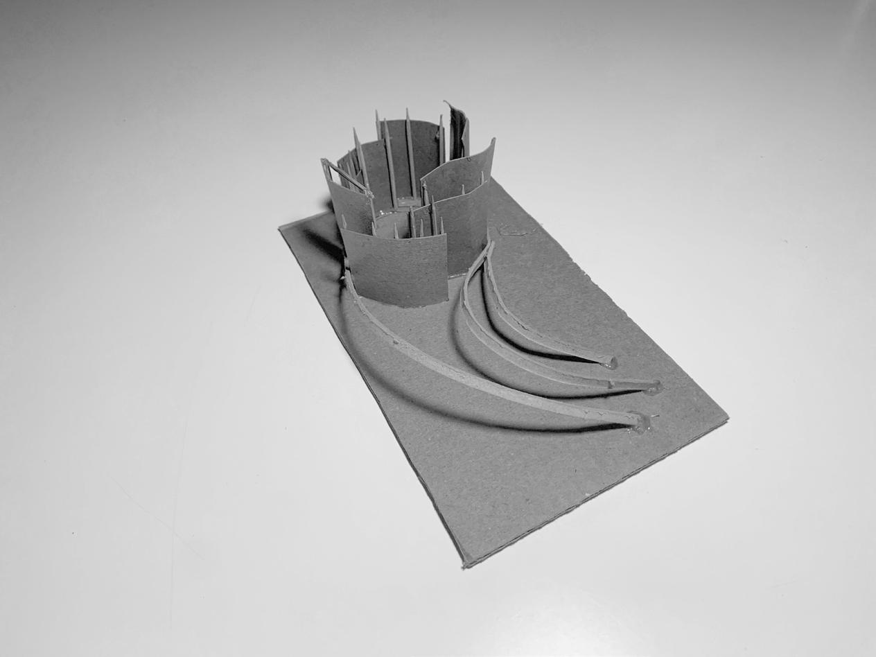
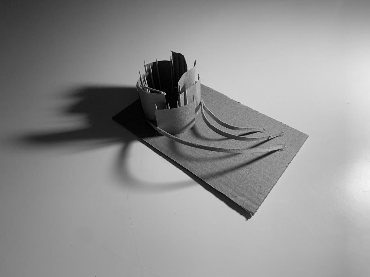
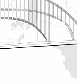
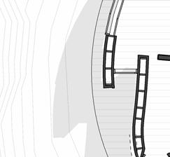
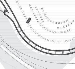
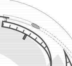
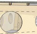
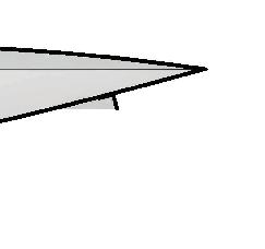
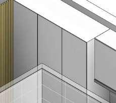
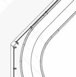
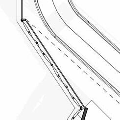
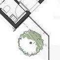
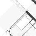
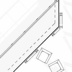
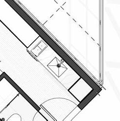
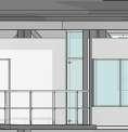
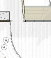
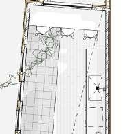
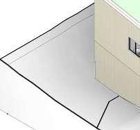
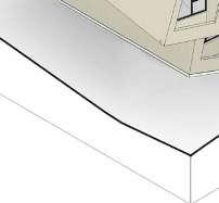
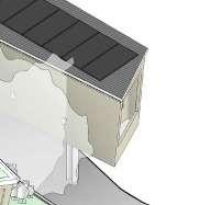
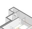
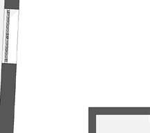
DIAGRAMS & SITE MODEL
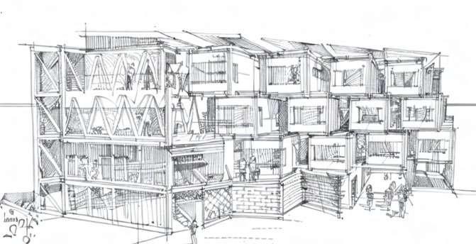
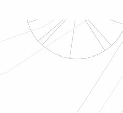
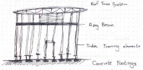
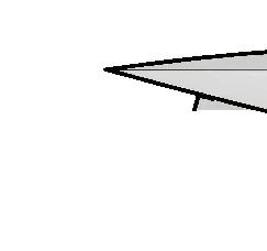
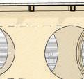
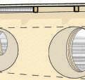
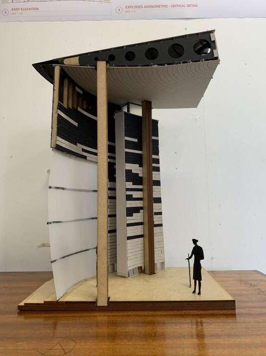
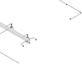
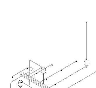
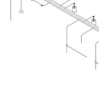
Exploded axonometric showing structure and use of spaces within the building envelope.
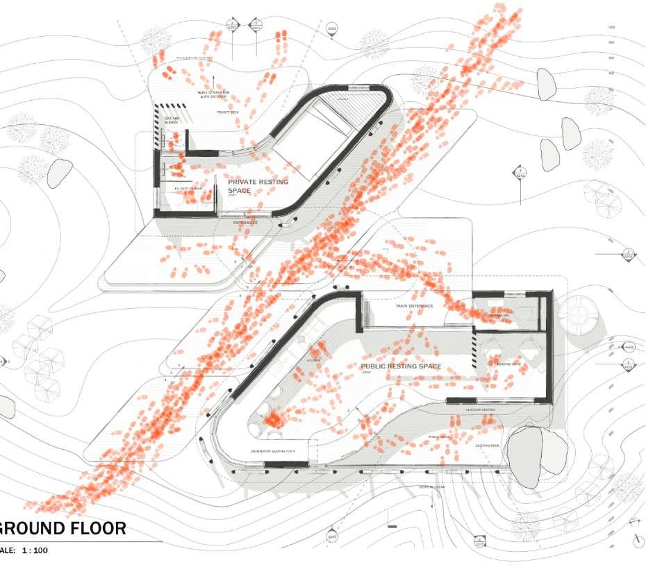
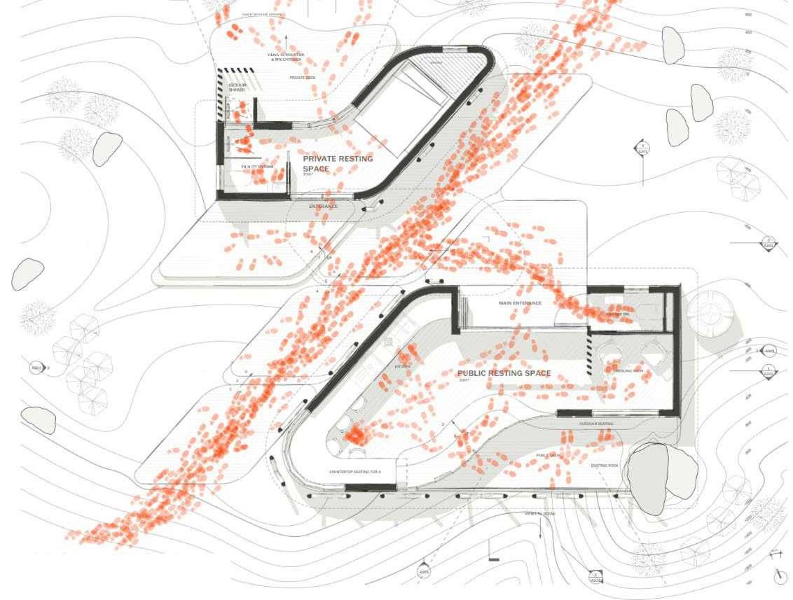
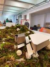
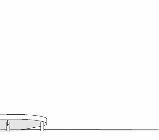
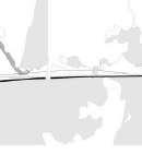
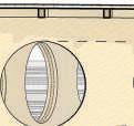
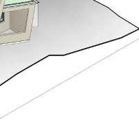
5 Timber beams roof structure Skylight I-Beam Lintels Public resting space timber roof support structure Private resting space Public interior Public exterior (threshold) Private Exterior Semi-private interior Private interior (WC) EX 02 CLIMATE SHELTER - CONCEPT DRAWINGS NOA CASTRO L ONEL MOSS KATE HALLE Site Model 1:100
0.1
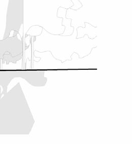
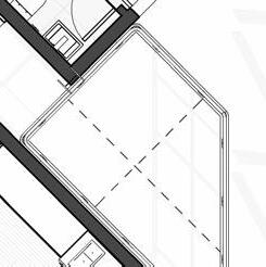
Movement diagram Roof Timber beams roof structure Skylight I-Beam Lintels Public resting space timber roof support structure Private resting space Public interior Public exterior (threshold) Private Exterior Semi-private interior Private interior (WC)


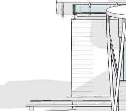


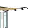
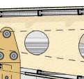
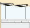
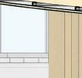
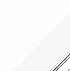
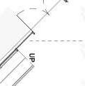
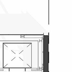
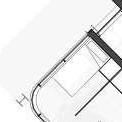
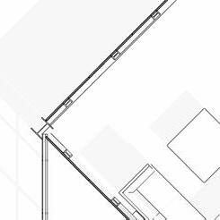
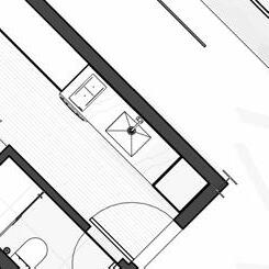
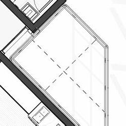
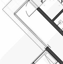
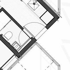
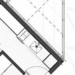
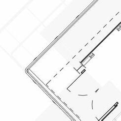
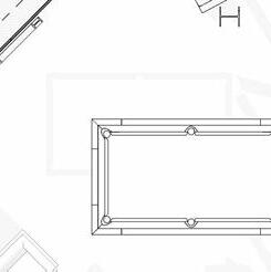
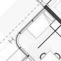
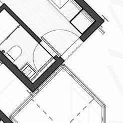
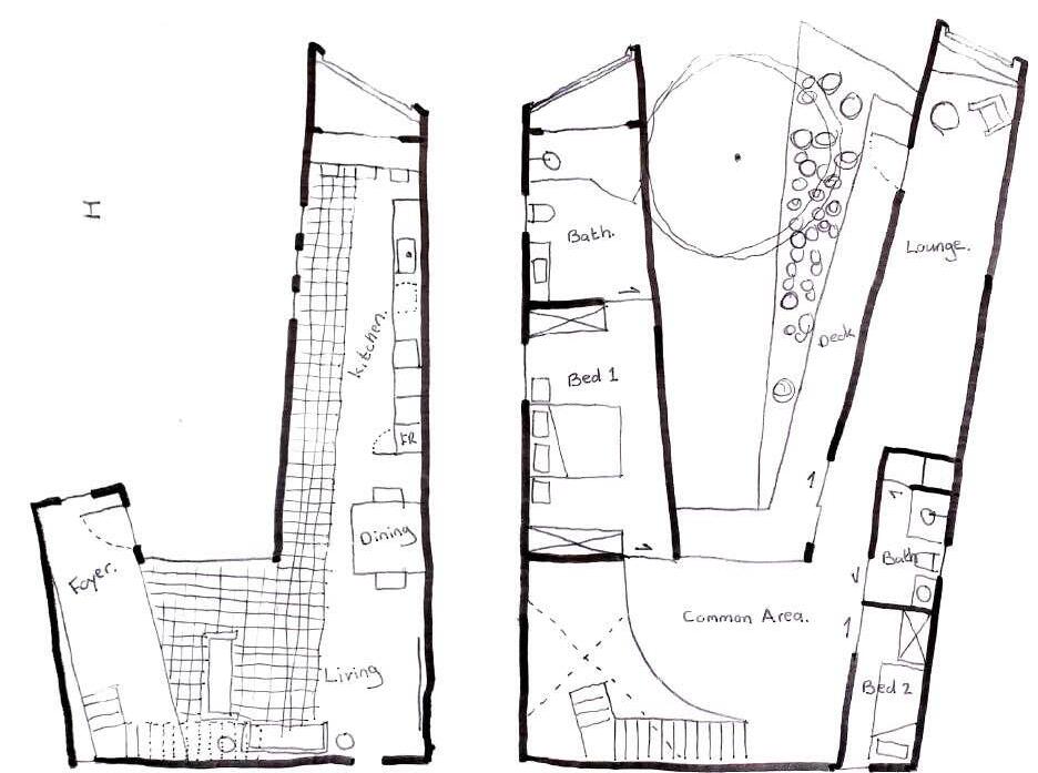
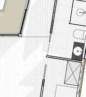
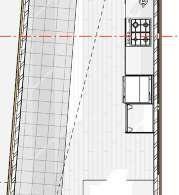
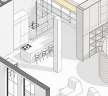
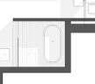
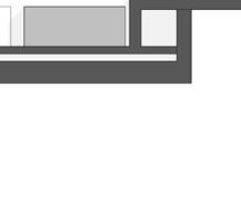
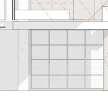
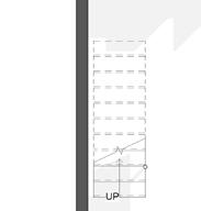
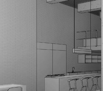
6 A302 A302 A301 1 4 1 UP PRIVATE DECK OUTDOOR SHOWER EN SUITE BATHRM. PRIVATE RESTING SPACE VIEWS TO OCEAN COUNTERTOP SEATING FOR 4 PUBLIC RESTING SPACE VIEWS TO MOUNTAIN & WATCHTOWER OUTDOOR SEATING ENTERANCE EXISTING ROCK 23.00° N 3 6 5 UP UP UP UP DECK TO MATCH SITE CONTOURS 22m 10m Bi-FoldingDoors 1 A203 m² POWDER RM. m² READING NOOK -600 -450 -300 -150 300 0 -128 600 3 1 2 3 4 5 6 1680 1800 2930 1750 3480 4680 A B C F 1800 1775 48° 1800 1800 1800 1800 1800 1800 MAIN ENTERANCE Timber decking 11 m² KITCHEN 150 900 80 1800 150 2980 905 600 725 150 2980 150 1685 80 165 150 window door opening wall & room layout 9349 exterior perimiter 1015 965 240 600 1005 Sink A401 4 A501
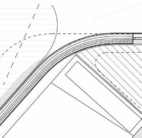
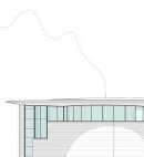
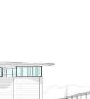
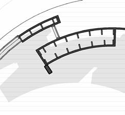
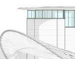
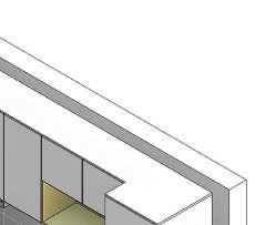
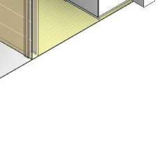
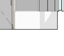
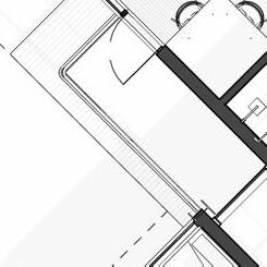
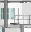
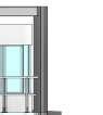
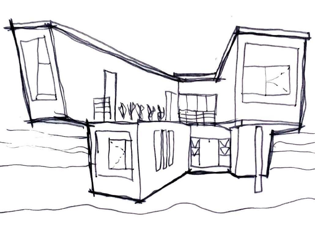
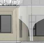
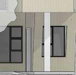
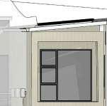
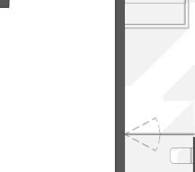
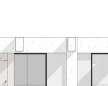
0.1 Floor Plan South Elevation Exploded Axonometric View
GENERAL LAYOUT FINAL DRAWINGS
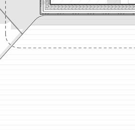
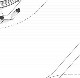
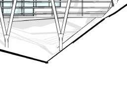
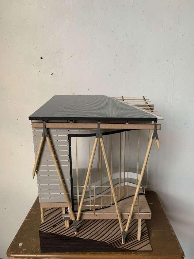
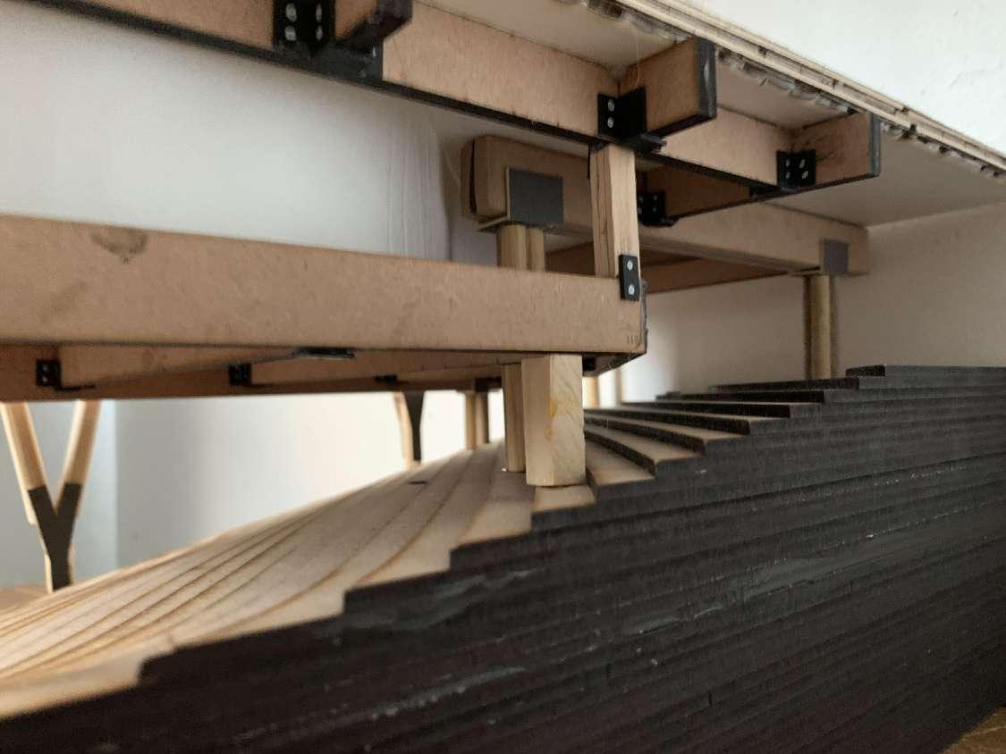
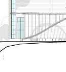
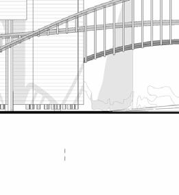
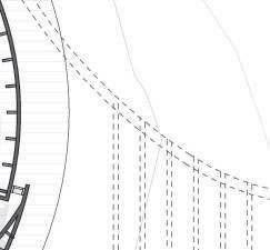
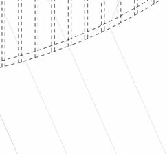
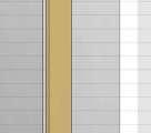
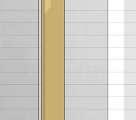
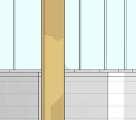
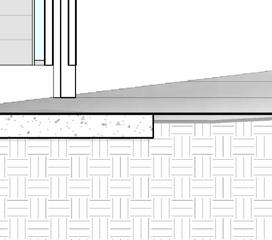
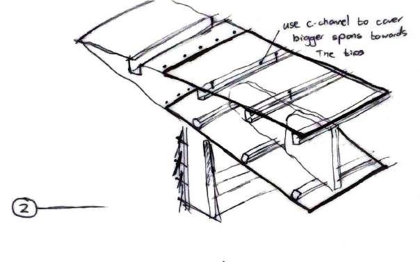
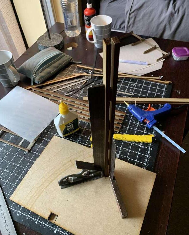
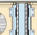
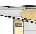
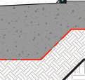
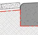
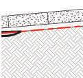
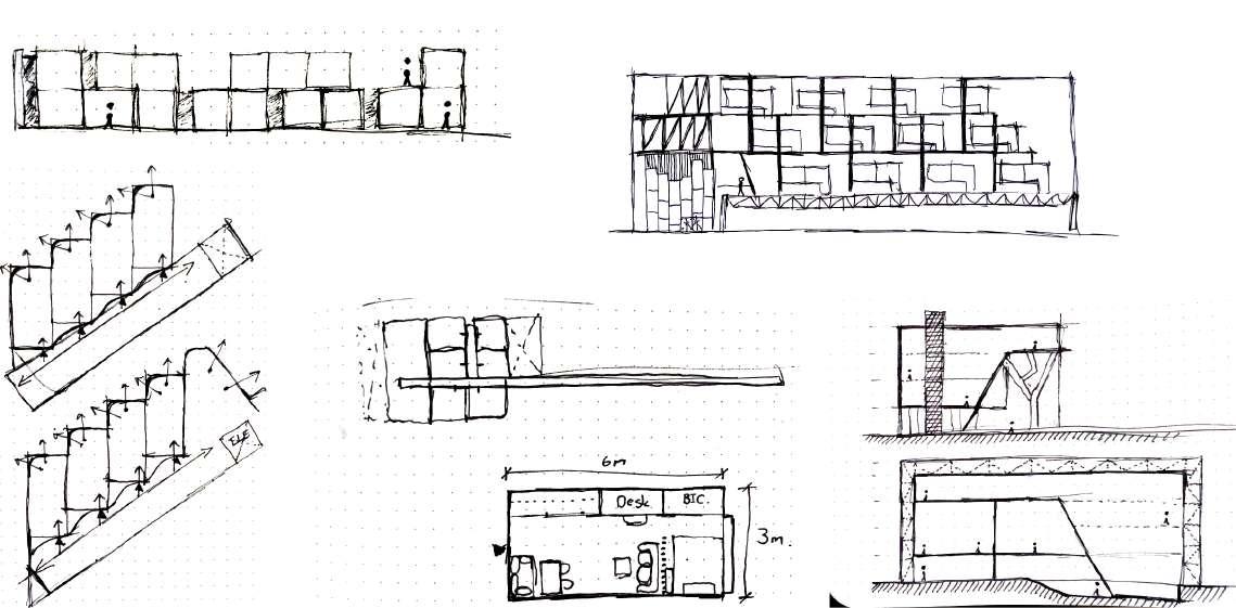
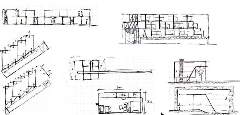
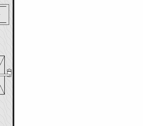
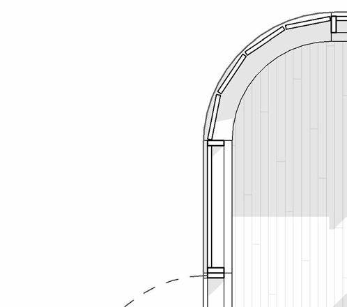
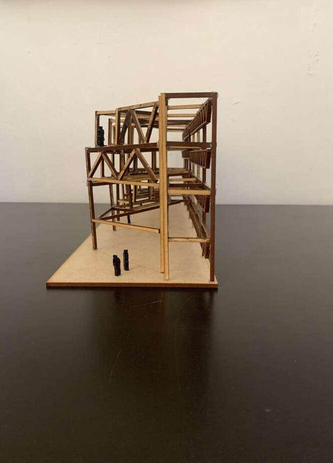
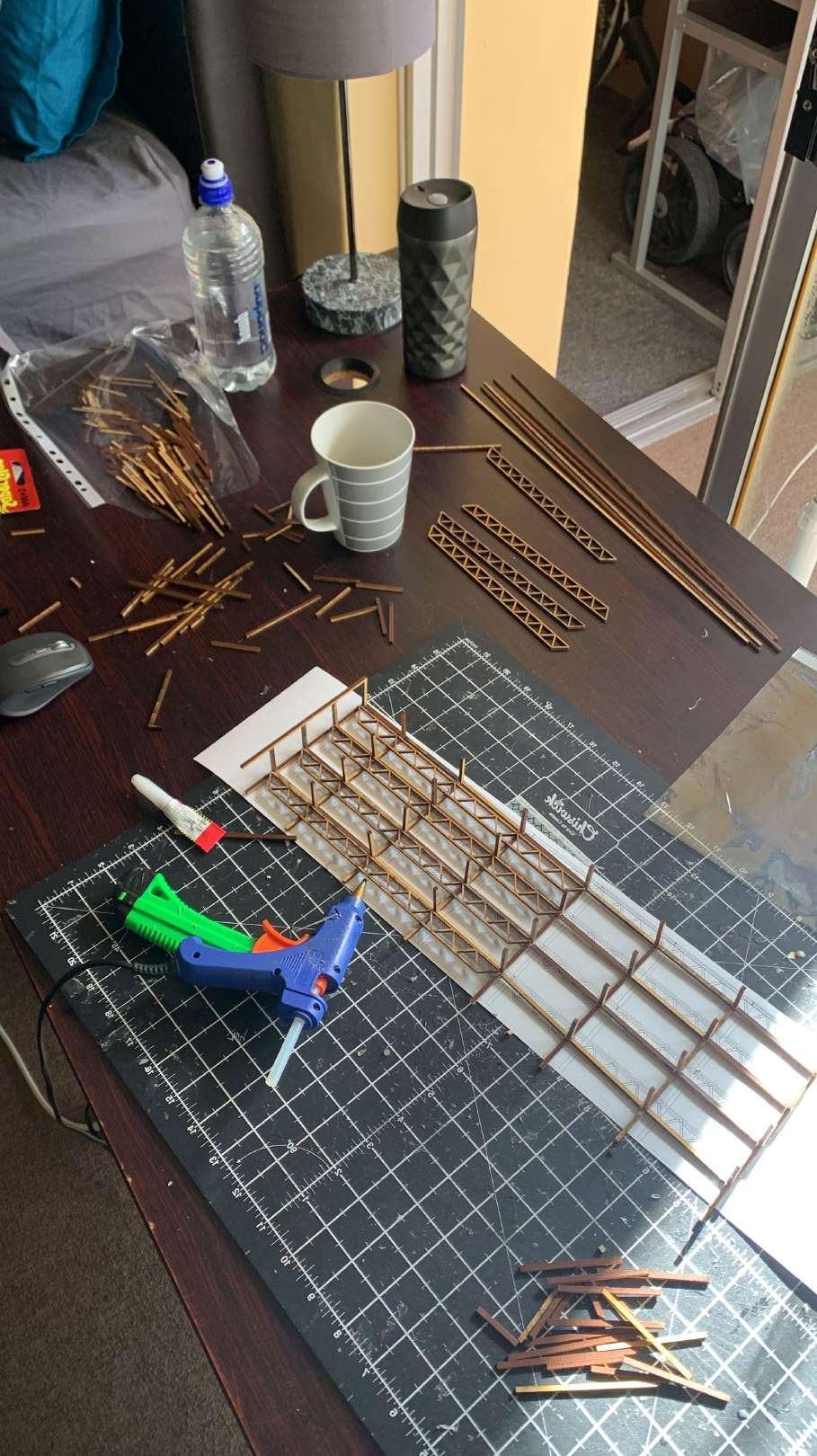
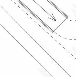
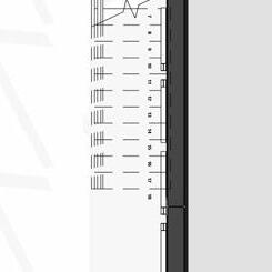
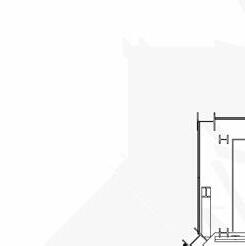
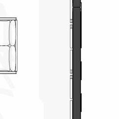
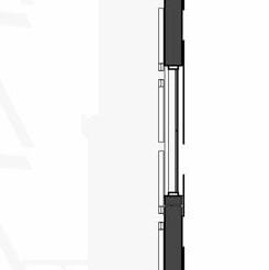
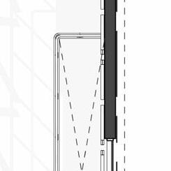
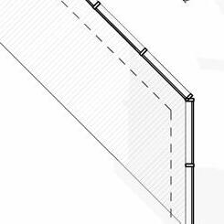
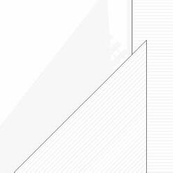
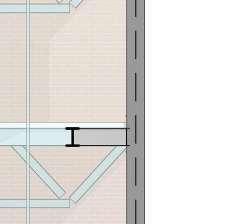
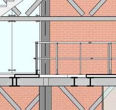
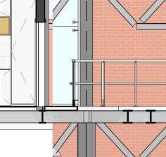
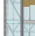
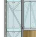
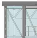
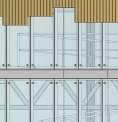
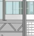
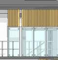
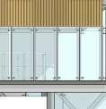
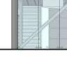
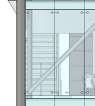
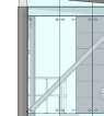
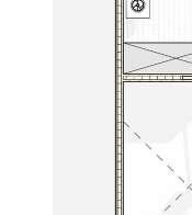
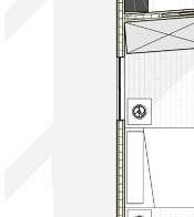
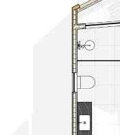
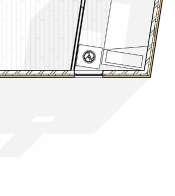
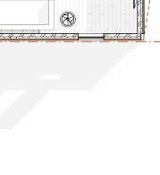
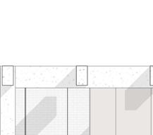
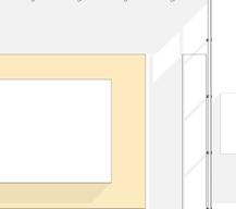
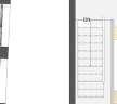
This project consisted of technically resolving the Climate shelter in section.
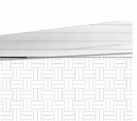
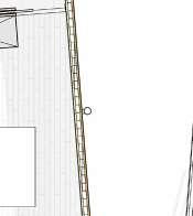
This mean producing a 1:20 section, 3x Detailed drawings & a 1:10 sectional model of the structure
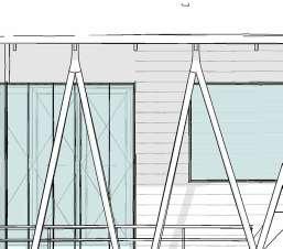
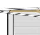
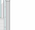
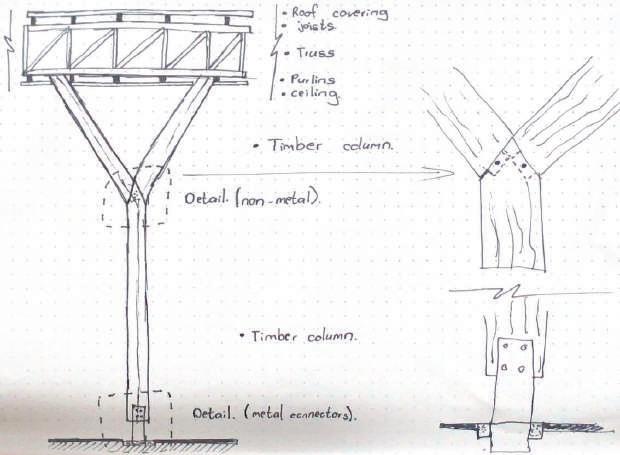
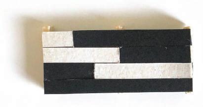
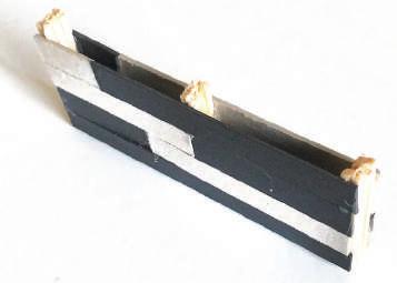
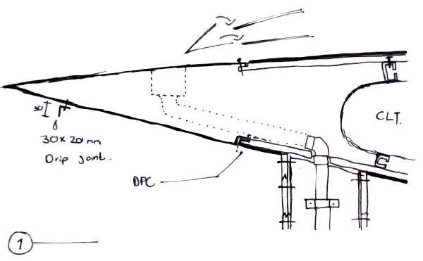
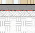
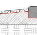
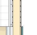
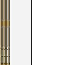
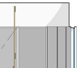
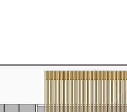
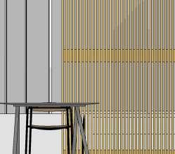
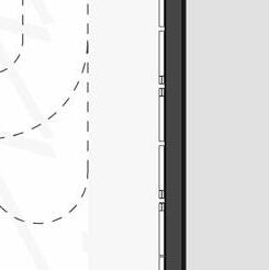
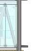
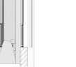
15x160mm Timber rain screen panels fixed to timber battens with 10mm reveal between panels.
Organic, slanted SA Pine columns as per SANS 1783-2/1460/10149 fixed at the base and top with 12mm M/S plate bolted with M12 bolts
Bi-folding doors as per the door schedule
Partially threaded timber screws for CLT wall To CLT Celling connection
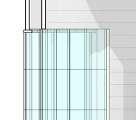
All windows and door opening as per the Window & Door Schedule. All glass in accordance to the SANS 10400.
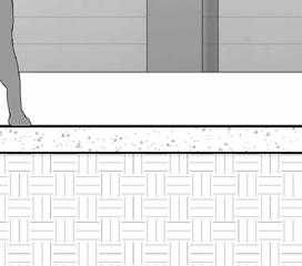
110x22mm Timber decking Nailed to joists below @ 150mm c.c as per SANS 10163
Rocks to prevent ground erosion due to drip water
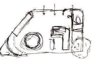
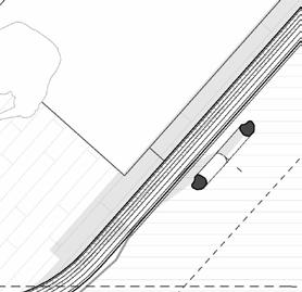
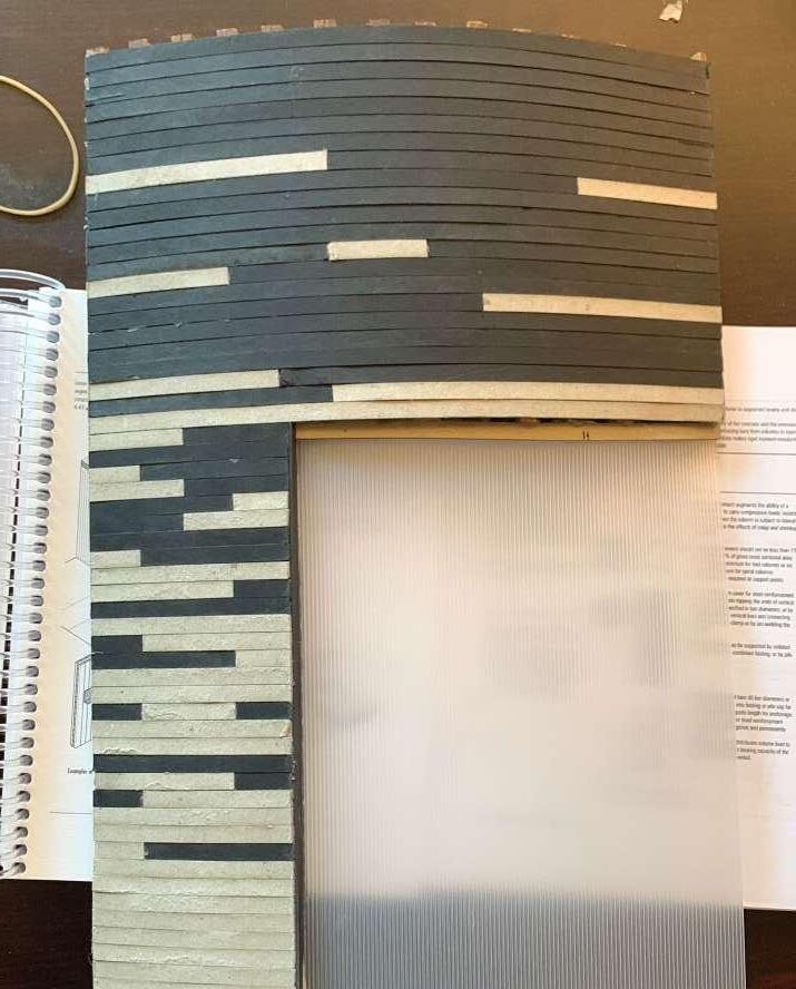
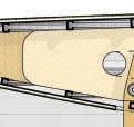
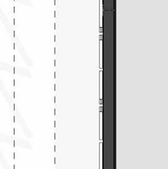
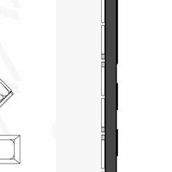
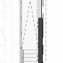
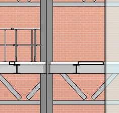
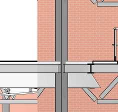
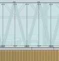
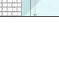
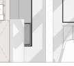
7 1:20 SECTIONAL
0.2
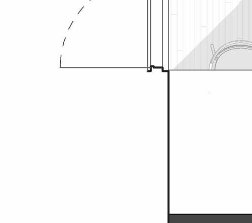
DEVELOPMENT
00 GROUND FLOOR +0.0 02 Lintel +3000 -01 Lower Step -600 01 Upper Level +600 03 Roof +360.0 4 5 6 600 2400 600 600 975 3555 1150 730 3700 150 830 150 400 215 3 m² MAIN ENTRANCE Timber decking
KITCHEN 11m2 0 -150 0 8° Slope -300 Balustrade wall minimum 900mm high, as per SAN10400 Part M. Design as per specialist 7 m² PUBLIC DECK ? 2 4 2 1
INT EXT Secondary beam structure Secondary beam structure 2213 150 2168 300 300
Two-tone tile backsplash
150
2400 Storage
Curved wall 2454 6175 2355
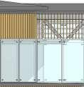
from roof
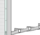
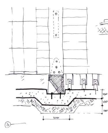
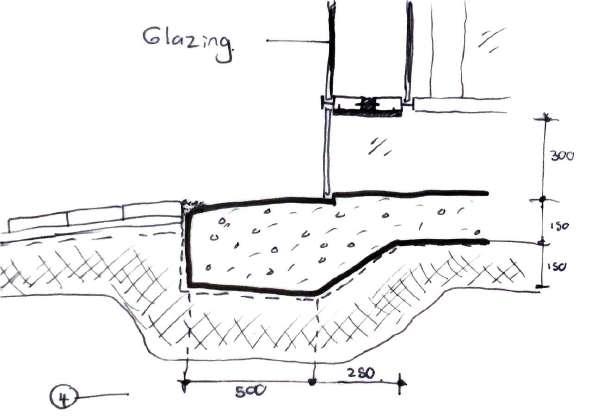
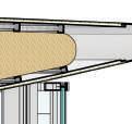
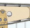
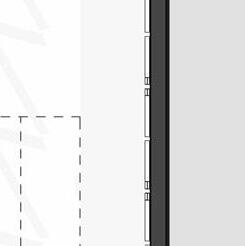
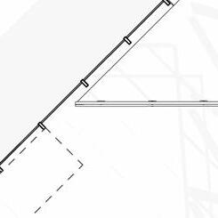
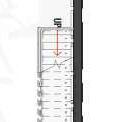
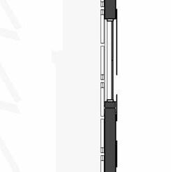
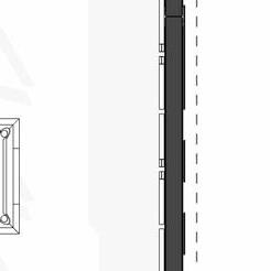
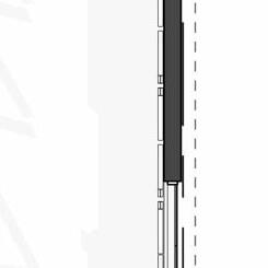
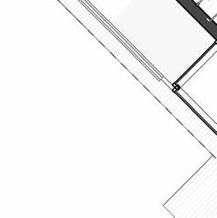
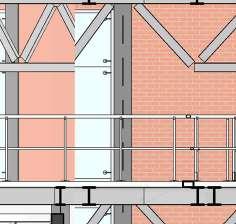
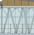
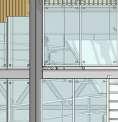
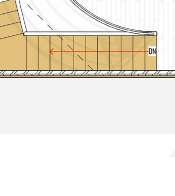
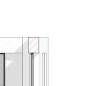
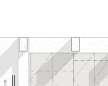
8 DETAILS SECTIONAL DEVELOPMENT 0.2 04 Lintel +3000 05 Upper Roof +3600 4 3 m² MAIN ENTRANCE Timber decking Mullion fixed to aluminium flashing shaped according to architect's specification 25mm UV treated glazed panel 150 EXT INT Reynaers_CW-50 Mullion-Transom Vertical 104.5mm fixed to aluminium plate according to architect's specifications Reynaers_CW-50 Mullion-Transom Horizontal 104.5mm Reynaers_CW-50 Structural MullionTransom Vertical 104.5mm to support roof joists & structure. Self-adhere membrane, flashing prestrip Aluminium plate shaped according to architect's specifications and fixed to timber battens with nails 8° 400 400 320 10mm Marine ply ceiling board fixed to joist from below with nails @ 900mm t 04 Lintel +3000 6 175x75mm dimensioned lumber beam fixed to 10mm M/S plates on either side with M12 bolts Custom made M/S bracket fixed to M/S pivot arm with a M12 bolt to engineers specifications Custom M/S base plate fixed to timber beam with M12 bolts 400 400 118X38mm Timber battens fixed to rafter below with nails @ 400mm c.c. 115x38mm Timber rafter fixed to M/S bracket below @ 900mm centres Organic, slanted SA Pine columns as per SANS 1783-2/1460/10149 fixed at the base and top with 10mm M/S plate bolted with M12 bolts 105 235 10mm Marine ply ceiling board fixed to joist from below with nails @ 900mm 350 20 118 138 Curved Wall 20mm Roof covering fixed to timber joist below @ 400mm c.c -01 Middle Lower Step -30.0 4 170 Foundations according to SANS 2001-CM2, according to engineer specifications. As well as in accordance with SANS 10400-H for foundations. 250 micron damp proof membrane [DPM] under all surface beds. 140Ø M/S Base plate With J-Hook concrete anchors M12 Bolts 130Ø Timber Post cut to length and fixed at top and bottom to M/S base plates 170x110x10mm M/S upper base plate that connects post to structural beam M12 Bolts @ 70mm centres 235x150mm Flitch Beam 12 mm M/S plate bolted to 2 x 67x235mm G20 Dimensioned Lumber with M12 bolts 3 m² MAIN ENTRANCE Timber decking Rebar according to engineers specifications VAR Measurement to be determined on site according to topography NGL Joist hangers according to engineers specifications 150 22 110 110x22mm Timber decking Nailed to joists below @ 150mm c.c as per SANS 10163 -130 1:10 Sectional Model Lower roof Detail 1 SCALE: 1:10 Upper roof Detail 2 SCALE: 1:10 Foundation Detail 3 SCALE: 1:10
PROPOSAL DATA
TYPE: Conceptual design
DATE: 17 April - 19 May 2023
LOCATION Lunuganga Estate, Sri-Lanka
PROFESSOR Tomà Berlanda
COLLABORATORS Clint Abrahams
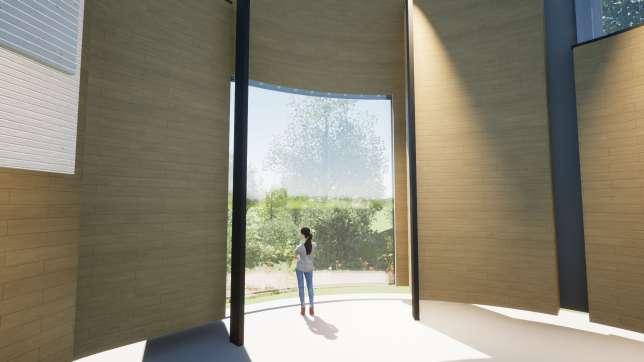
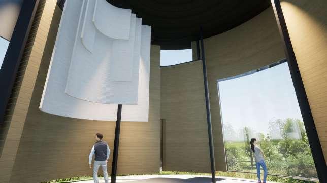
A sacred space is a place where you can make yourself vulnerable to some extent Within a safe, protected enclosure, It is an area where you can seek quiet time with a small possibility of being disturbed.
I intend to shield the user against surrounding elements by developing a space with Multiple layers as they enter. Doing so will convince the user that they are entering a Safer & safer space with each passing layer.
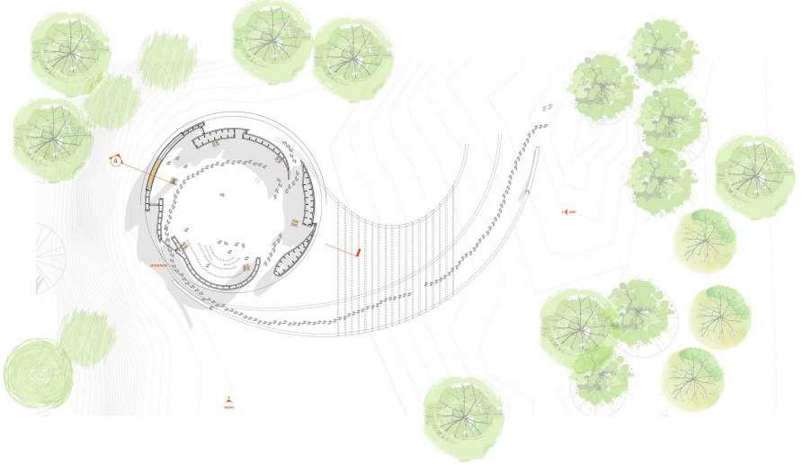
9 SACRED
0.3
SPACE
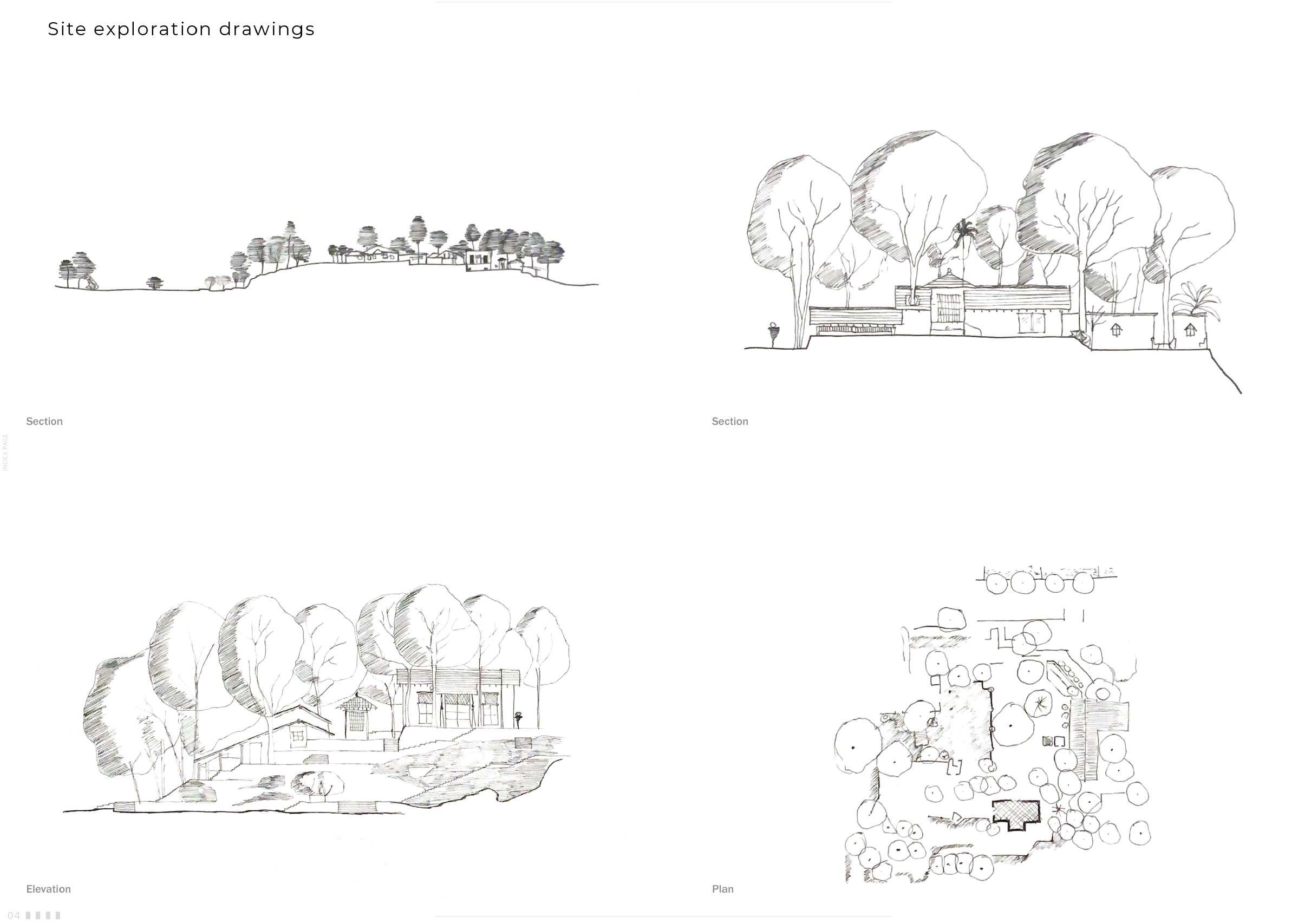
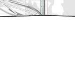
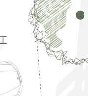
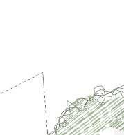
10 SITE ATMOSPHERIC SKETCHES 0.3
Atmospheric sketches of Lunuganga estate in Sri-Lanka
CONCEPT DEVELOPMENT
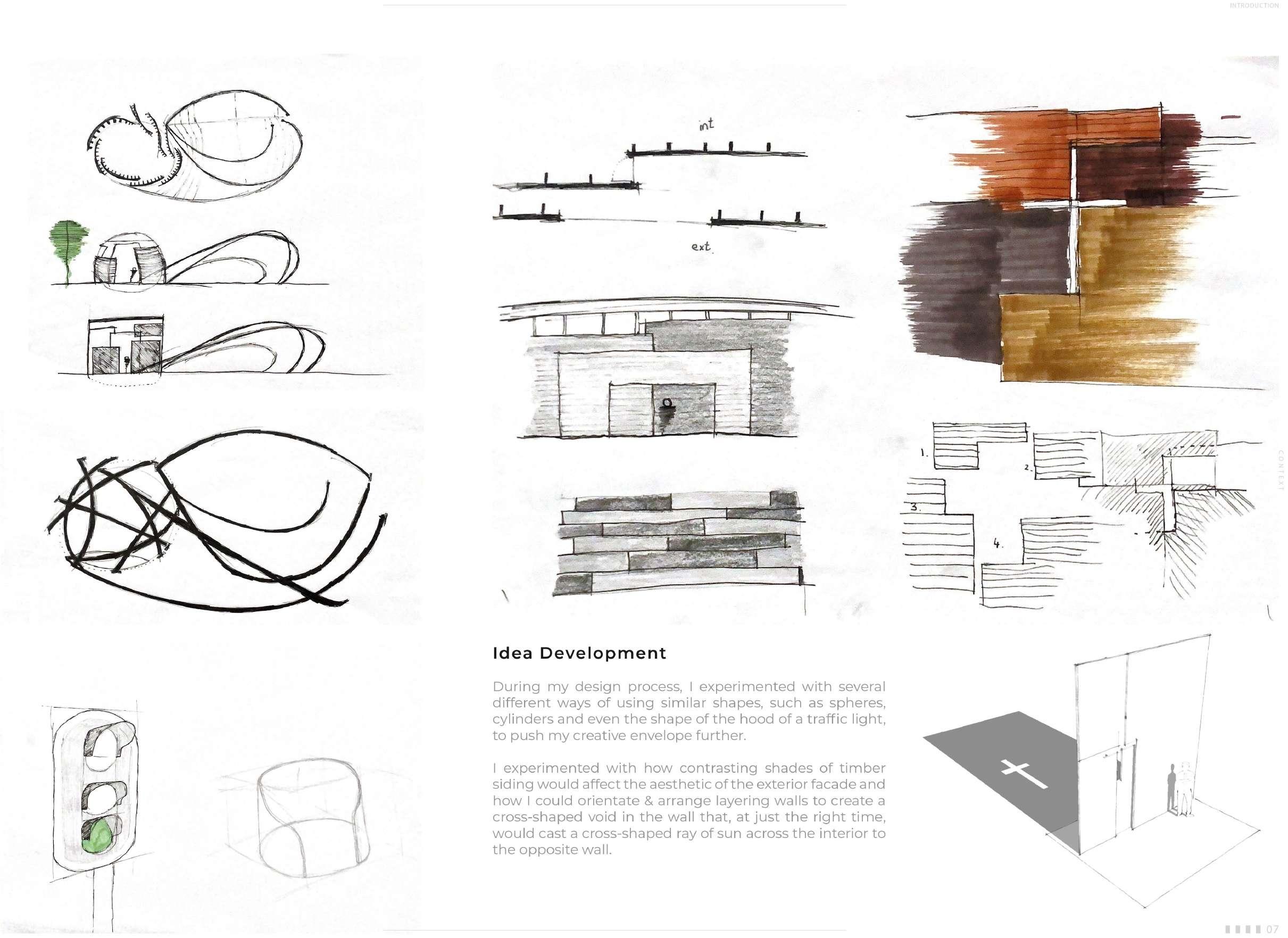
Idea Development
During my design process, I experimented with several different ways of using similar shapes, such as spheres, cylinders and even the shape of the hood of a traffic light, to push my creative envelope further.
1 experimented with how contrasting shades of timber siding would affect the aesthetic of the exterior facade and how I could orientate & arrange layering walls to create a cross-shaped void in the wall that, at just the right time, would cast a cross-shaped ray of sun across the interior to the opposite wall.
11
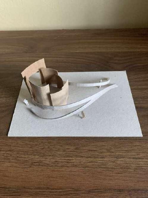
Form Development
The model-making process was an exhilarating stage for me. I realised I had an idea of the model I planned to make. However, as I glued materials together, the task at hand “took over”, and my final product displayed something different than initially planned.
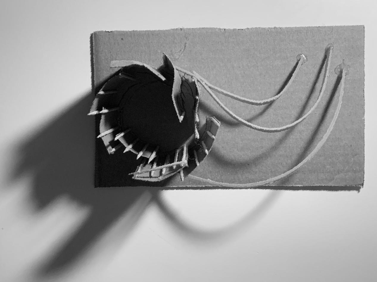
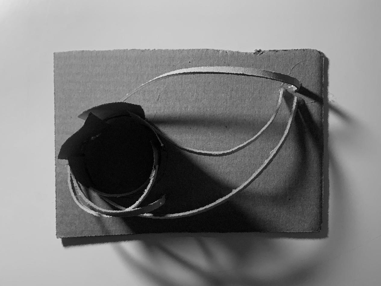
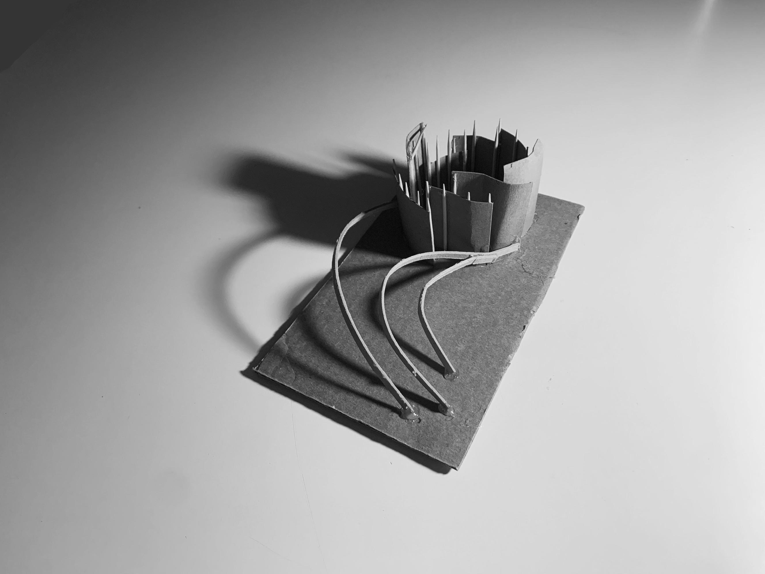
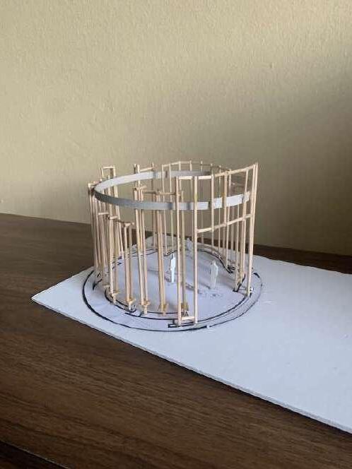
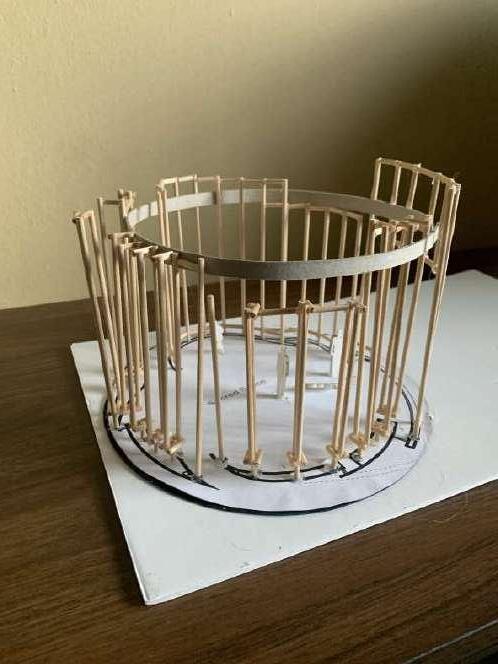
It was in this act of model-making that I developed the scheme of having a main chapel that is completely under the roof and protected. Additionally, a curved timber installation on the exterior will wrap (hugs) the main chapel structure. This timber installation will provide a degree of shading but, more importantly, a place for social gatherings.
12
CUTTING
0.3
SITE
MODELS
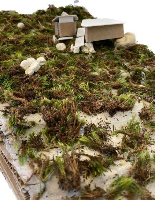
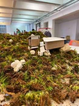
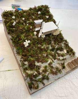
Concept models
C O N T E X T 09
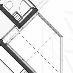
13 FORM
ELEVATIONS CONCEPT SKETCHES 0.3 Concept 01 Elevation Concept 02 Elevation INDEX PAGE 08 Concept 01 Elevation Concept 02 Elevation INDEX PAGE 08
&


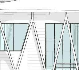
14 FINAL DRAWINGS 0.3 Exploded Axonometric Diagram South Elevation East Elevation Roof Roof truss structure Glazed ring connecting the roof and walls Timber framing structure supporting the timber siding Timber columns supporting the roof assembly Glazing Siding fixed to timber framing Organic timber canopy Exploded Axonometric 16 0m 5m 10m 2 North Elevation SCALE: 1:200 1 East Elevation SCALE: 1:200 FINALSET OF DRAWINGS 0m 5m 10m 1 East Elevation SCALE: 1:200 FINALSET OF DRAWINGS 14 A B 1 Floor plan SCALE: 1:25
15
0.3
RENDERS
RV2- View to outside
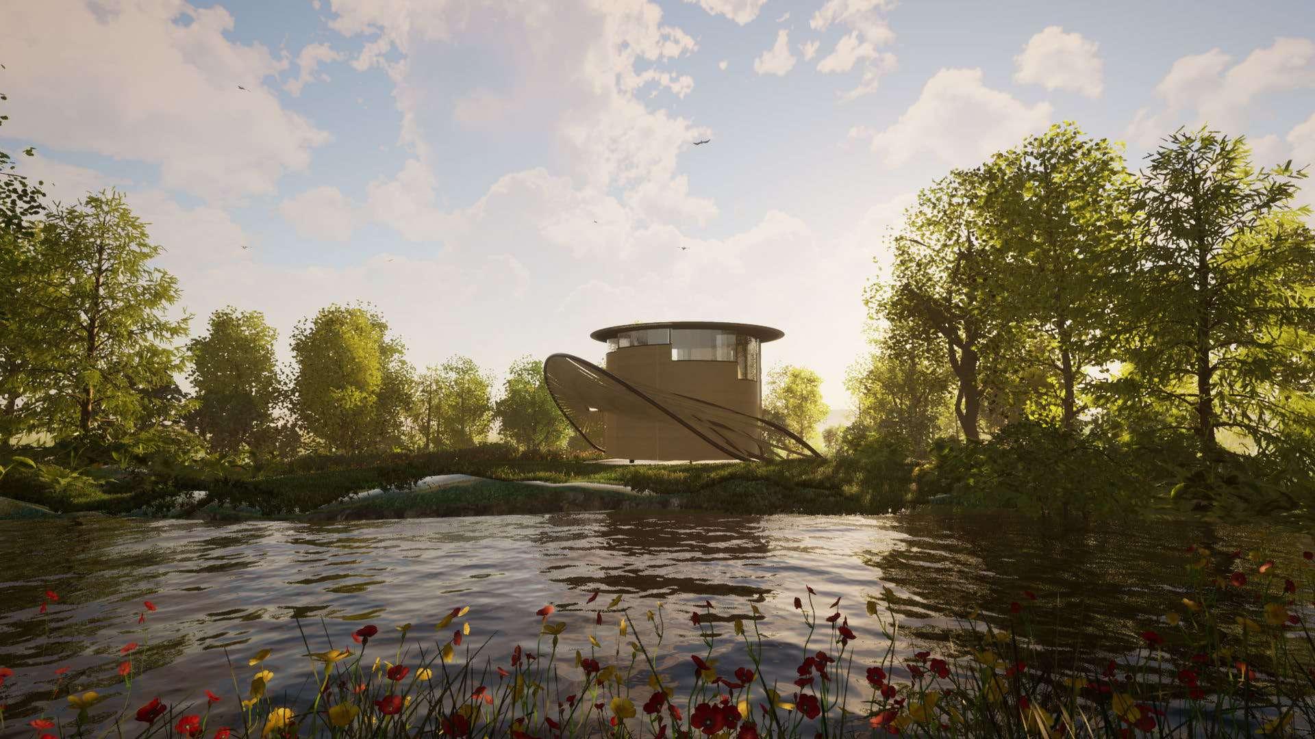
RV1- Perspective of the Sacred space in its environment
RV3 Perspective from across the pond
17 RENDERINGS
RV4- Perspective from underneath the timber canopy


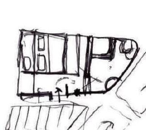
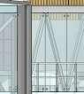
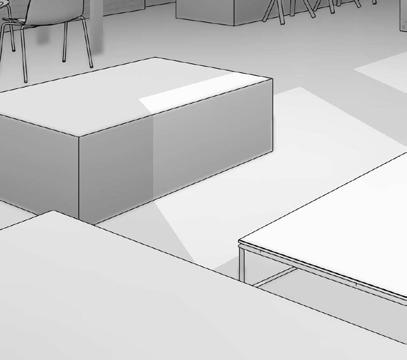
16 SECTIONAL DEVELOPMENT 0.4 FIN. FLOOR +0.0 LINTEL +210.0 LEVEL +390.0 LEVEL +570.0 ROOF +750.0 Glazing Note roof note roof structure note cladding note Framing Note Floor Note 4500.0 300.0 6600.0 Interior cladding finsish Opening Opening # Interior cladding finsish Interior cladding finsish SCALE: SHEET SIZE: PROJECT NO: ISSUE DATE: DRAWING NO: PROJECT STATUS: ARCHITECT: DRAWING TITLE: REVIT 2023 SHEET NO MSSLIO001MSSLIO001 LIONEL MOSS A1A1 SACRED SPACE EMAIL: THEMETRICDIMENSION@GMAIL.COM 20 A201 SECTIONS 0001 20/01/2023 SCALE: 20 1 Section 5 NO. DESCRIPTION DATE Structural columns that support the roof structure independantly from the external walls Structural Framing proposal Structural Framing proposal External Cladding Structural Framing proposal External Cladding 1:50 Structural Model Cladding exploration
17
0.4 SCALE: SHEET SIZE: PROJECT NO: ISSUE DATE: DRAWING NO: PROJECT STATUS: ARCHITECT: CLIENT: DRAWN BY: STUDENT NO: DRAWING TITLE: REVIT 2023 SHEET NO O001 MSSL MOSS ONE L DATE A1 DATE DESCRIPTION BY SACRED SPACE TEL: 076 877 0999 EMAIL: THEMETRICDIMENSION@GMAIL.COM WEBSITE: METRICDIMENSION.MYPORTFOLIO.COM VAR A502 DETAILS EX04 25.07.2023 DESIGN DEVELOPMENT 03 Author TECHNOLOGY II APG 2021W, 2023 CENTLIVRES BUILDING UNIVERSITY OF CAPE TOWN 1 DESK CRIT 1 01.08.2023 2 DESK CRIT 2 08.08.2023 3 DESK CRIT 3 15.08.2023 4 PRELIMINARY SUMBISSION 22.08.2023
DETAILS DESIGN SKETCHES
18 1:20 SECTIONAL
0.4 FLOOR LINTEL +210.0 LEVEL+390.0 LEVEL+570.0 ROOF +750.0
MODEL
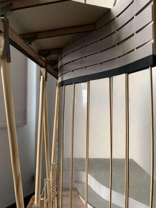
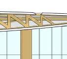
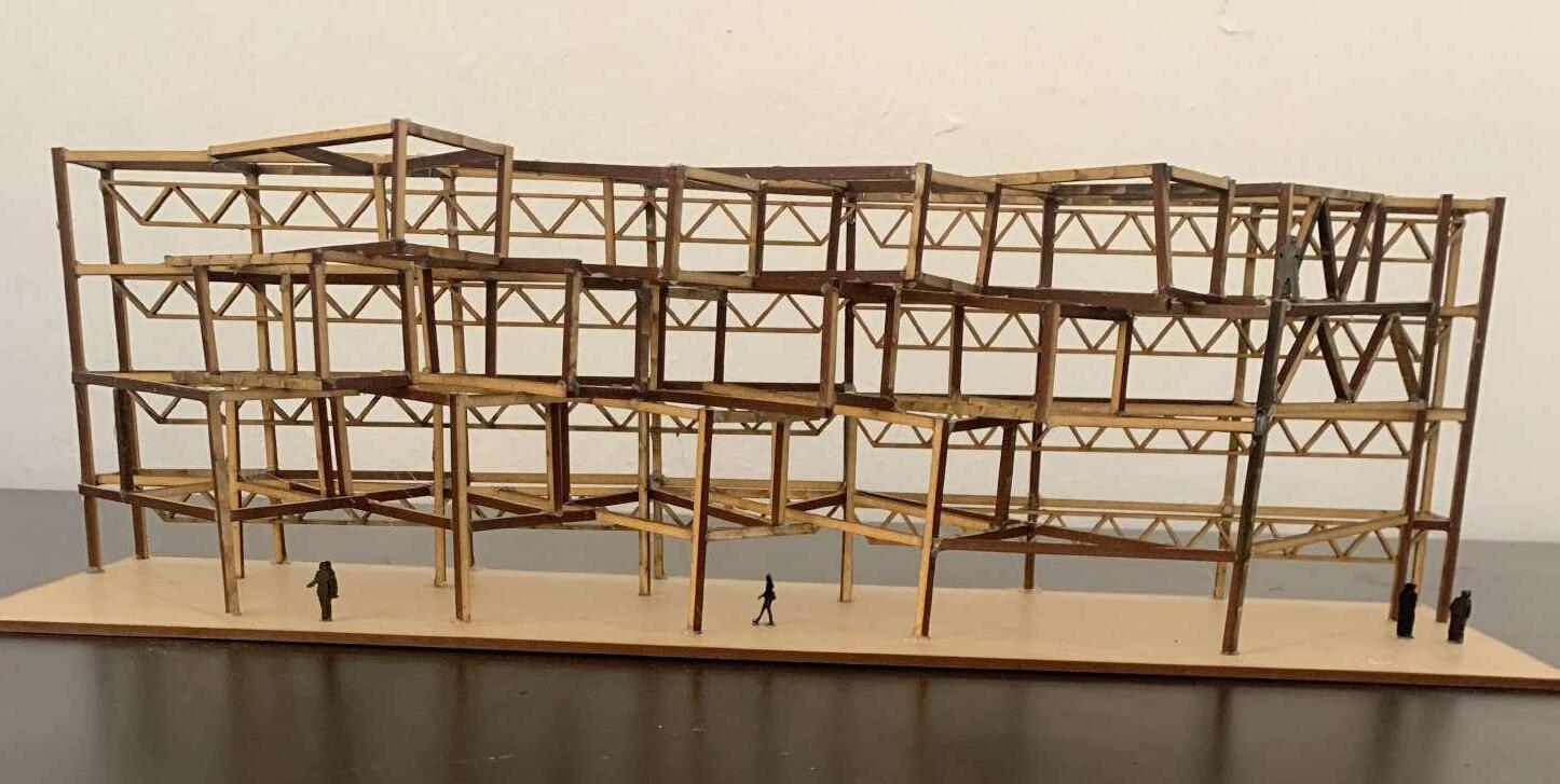
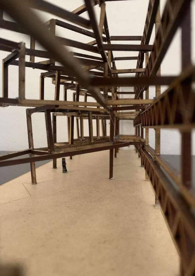
The project requirements expected us to produce a 1: 20 Sectional model the illustrates the structural systems & building envelope.
SECTION AA FINAL DRAWINGS

No variation or instruction can exempt the contractor and/or subcontractors from complying with the National Building Regulations SANS 10400.
H: Consult the architect for clarification on any unclear or ambiguous aspects of this drawing and promptly report errors, discrepancies, or omissions.


I: The architects retain the copyright of this drawing.
CONSTRUCTION NOTES:
1. FOUNDATIONS: (to structural engineer's specifications)


1.1 All foundations to comply with SANS 10400-H

1.2: New slab thickening to Eng. Spec where the two new timber walls are to be built.
FLOORS 2
2.1 All floors to comply with SANS 10400-J and SANS 10082
MBER T 3 3.1. Timber framed structures built in accordance with SANS 10082.
3.2. Timber roof trusses manufactured in accordance with Part L Roofs of SANS 10400 'The Application of the National Building
WALLS 4 4.1 All walls to comply with SANS 10400-K.


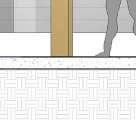
4.2 exterior walls using timber posts & cladding.
4.3 DPC's to all external door and window openings. 375 micron embossed DPC.

4.4 Timber lintels over all windows and doors exceeding 3000mm. Minimum two layers (100mm)

5.WINDOWS AND DOORS

5.1 Glazing complies with SANS 10400 -0 & N. 5.2 Glass doors that have more than 1sqm or less than 500mm above FFL to have laminated 6mm clear safety glass.

5.3 Aluminum windows and doors made to size.
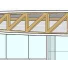
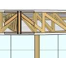
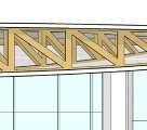
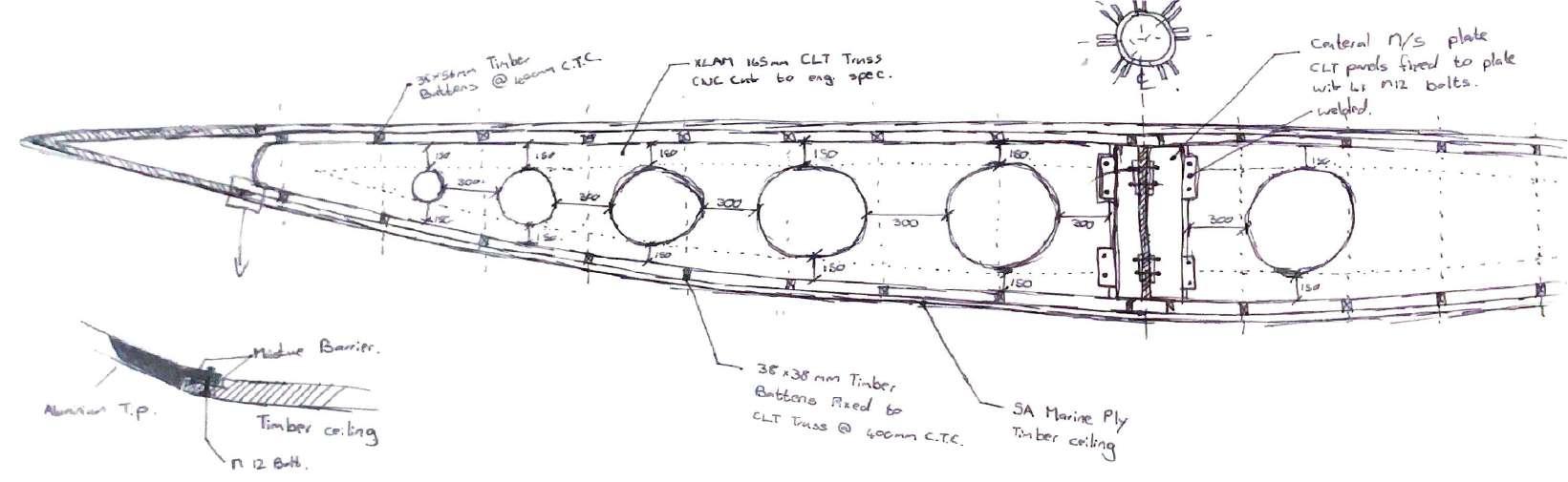
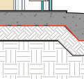
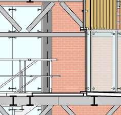
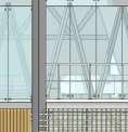
19 FIN. FLOOR +0.0 LEVEL 1 +390.0 LEVEL 2 +570.0 ROOF +750.0 A501 5 A501 3 500 2710 4440 50 300 A501 4 XLAM TX99 CLT Truss CNC cut to engineer's specifications to reduce weight. 38x56mm Laminated radial timber battens fixed to top of CLT truss with nails @ 400mm C.T.C. Central R400 M/S plate. CLT trusses fixed to support plates with xM12 galvanized bolts. 200x80mm M/S support plates welded to central core. See detail 38x38mm Laminated radial timber purlins fixed to bottom of CLT truss with nails @ 400mm C.T.C. 400 400 400 270mm Built up beam with two 279x89 & 92x92mm spacer blocks between. Fixed with two M12 bolts @ 1000mm centers. Foundations according to SANS 2001-CM2, according to engineer specifications. As well as in accordance with SANS 10400-H for foundations. A501 1 6650 Interior cladding finish as specified by architect Interior cladding finish as specified by architect Interior cladding finish as specified by architect 4840 860 38x56x3mm Curved C-Channel battens fixed to top of CLT truss with self-threading screws @ 400mm C.T.C. 4850 5750 6600 4800 0.25mm polyolefin Damp Proof Membrane underneath Surface bed. Laid on top of selected approved backfill compacted in 150mm layers. All windows and door opening as per the Window & Door Schedule. All glass in accordance with Part N of the SANS 10400. 500 500 150 300 240 300 340 300 440 300 510 300 540 140 150mm Offset from edge 8000 50x150mm Timber framing post fixed to lintel with M/S plate with M12 through bolts at 100mm centers 200 80 120x20mm timber shiplap siding consisting of boards joined edge to edge with overlapping Rabbeted joints fixed to structure with nails. SCALE: SHEET SIZE: PROJECT NO: ISSUE DATE: DRAWING NO: PROJECT STATUS: ARCHITECT: CLIENT: DRAWN BY: STUDENT NO: DRAWING TITLE: REVIT 2023 SHEET NO O001 MSSL MOSS LIONEL I DATE A1 DATE DESCRIPTION BY SACRED SPACE TEL: 076 877 0999 EMAIL: THEMETRICDIMENSION@GMAIL.COM WEBSITE: THEMETRICDIMENSION.COM 1 20 8/28/2023 9:51:11 PM SECTIONS EX04 25.07.2023 DESIGN DEVELOPMENT Michael Du Toit Christos Simos TECHNOLOGY II APG 2021W, 2023 CENTLIVRES BUILDING UNIVERSITY OF CAPE TOWN SCALE: 1 : 20 1 Section AA 1 DESK CRIT 1 01.08.2023 2 DESK CRIT 2 08.08.2023 3 DESK CRIT 3 15.08.2023 4 PRELIMINARY SUBMISSION 22.08.2023 This drawing is the property of THE METRIC DIMENSION Pty(Ltd) .and is copyright. GENERAL NOTES: A: Do not scale drawings. Only figured dimensions to be used and overall dimensions to take preference B: All dimensions are in millimeters unless stated otherwise. C: Contractor must verify all dimensions and levels on-site before starting work. D: This drawing must be considered alongside all other relevant drawings and specifications. E: All materials and workmanship must adhere to the National Building Regulations SANS 10400 and relevant SANS codes. F: Contractor must obtain written confirmation from the architect for any instructions that modify the contract before proceeding. G:
2 501 5 FINAL PIN-UP 29.08.2023 A201 01
0.4
38x56x3mm Curved C-Channel battens
250Micron DPC Between Timber ceiling and aluminum tip
3mm Aluminum tip fixed to CLT beam mechanically
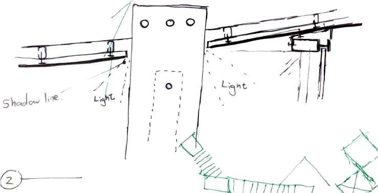
10mm Shadow line sealed with structural silicone
ROOF +750.0
120x20mm timber shiplap siding consisting of boards joined edge to edge with overlapping
100x210mm Laminated timber Lintel fixed to framing structure with 6mm M/S plate & 4x M12 through bolts. 20
Rabbeted joints fixed to structure with nails.
210 20 120

120x20mm timber shiplap siding consisting of boards joined edge to edge with overlapping
20 210 20
6x150x80mm M/S plate & 4x M12 through bolts @ 80mm hor. centers & 40mm ver. center.
100x210mm Laminated timber Lintel fixed to framing structure.
250Micron DPC between lintel & aluminium transom
50 50 80 40
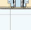
25mm UV treated exterior glazed panel
25mm UV treated interior glazed panel
250 micron damp proof membrane [DPM] under all surface beds.
200 x 100 x 60mm thick Concrete Weathered Charcoal colored paving blocks.
NGL
150
150 150 150 400 150 2.76°


Foundations according to SANS 2001-CM2, according to engineer specifications. As well as in accordance with SANS 10400-H for foundations.

270mm Built-up beam with two 279x89 & 92x92mm spacer blocks between. Fixed with two M12 bolts @ 1000mm centers.
25mm UV treated interior glazed panel
50x150mm Timber framing post fixed to ground with M/S anchor strap cast into concrete. Secure with M12 through bolts at 100mm centers
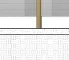
10mm Polished concrete screed. Finish as specified by client.
Rebar according to engineers specifications.
150mm Compacted Filling (G5).
250 micron damp proof membrane [DPM] under all surface beds. 0.25mm polyolefin Damp Proof Membrane underneath Surface bed. Laid on top of selected approved backfill compacted in 150mm layers.
0.25mm
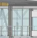
fixed to top of CLT truss with self-threading screws @ 400mm C.T.C. ROOF +750.0 38x56x3mm Curved C-Channel battens fixed to top of CLT truss with self-threading screws @ 400mm C.T.C. 140 220 80mm Split-ring connector tri-configuration consisting of a metal ring inserted into corresponding groves cut into the face of joining members & held in place by 1x M12 Bolt. (See Detail on A503) 3mm Aluminum fl;flashing according to architect's specifications 270mm Built-up beam with two 279x89 &92x92mm spacer blocks between. Fixed with two M12 bolts @ 1000mm centers. 38x38mm Laminated radial timber purlins fixed to bottom of CLT truss with nails @ 400mm C.T.C. XLAM TX99 CLT Truss CNC cut to engineer's specifications to reduce weight. 25mm UV treated exterior glazed panel Soft white downlight within boxed out recess around the timber column SCALE: SHEET SIZE: PROJECT NO: ISSUE DATE: DRAWING NO: PROJECT STATUS: ARCHITECT: CLIENT: DRAWN BY: STUDENT NO: DRAWING TITLE: REVIT 2023 SHEET NO O001 MSSL MOSS LIONEL I DATE A1 DATE DESCRIPTION BY SACRED SPACE TEL: 076 877 0999 EMAIL: THEMETRICDIMENSION@GMAIL.COM WEBSITE: METRICDIMENSION.MYPORTFOLIO.COM 8/28/2023 9:51:41 PM A501 DETAILS EX04 25.07.2023 DESIGN DEVELOPMENT TECHNOLOGY II APG 2021W, 2023 CENTLIVRES BUILDING UNIVERSITY OF CAPE TOWN SCALE: 1 10 5 Structural Column Footing SCALE: 1 10 4 Curtain panel cill SCALE: 1 5 3 Curtain panel head SCALE: 1 5 1 Wall Section SCALE: 1 5 2 Column - Truss Connection Michael Du Toit Christos Simos VAR 02 1 DESK CRIT 1 01.08.2023 2 DESK CRIT 2 08.08.2023 3 DESK CRIT 3 15.08.2023 4 PRELIMINARY SUBMISSION 22.08.2023 5 FINAL PIN-UP 29.08.2023
20 FIN. FLOOR +0.0 150 150 140 10 300 50 800 150 500 150 290 360
330 80 Interior cladding finish as specified by architect
500 50 400 50 EQ EQ FIN. FLOOR +0.0 25mm
25mm
Mullion
flashing
to
specification
UV treated Interior glazed panel
UV treated Exterior glazed panel
fixed to aluminium
shaped according
architect's
150mm
Foundations according to SANS 2001-CM2, according to engineer specifications. As well as in accordance with SANS 10400-H for foundations. 50 300
Compacted Filling (G5).
polyolefin Damp Proof Membrane underneath Surface bed. Laid on top of selected approved backfill compacted in 150mm layers.
25mm Compacted sand bed
Mullion fixed to timber spacer block according to architect's specifications
Rabbeted joints fixed to structure with nails.
50x150mm Timber framing post fixed to lintel with M/S plate with M12 through bolts at 100mm centers
L51x52x3.2mm Drip joint fixed to aluminum sheeting with M8 bolts @ 100mm C.T.C
6x150x80mm M/S plate & 4x M12 through bolts @ 80mm hor. centers & 40mm ver. center.
M12 Countersunk screws @ 50mm C.T.C.
AXONOMETRIC - CRITICAL DETAIL
SCALE:
38x56x3mm Curved C-Channel battens fixed to top of CLT truss with self-threading screws @ 400mm C.T.C.
Custom 80mm Split-ring connector tri-configuration consisting of a metal ring inserted into corresponding groves cut into the face of joining members & held in place by 1x M12 Bolt & washer
XLAM TX99 CLT Truss CNC cut to engineer's specifications to reduce weight.
38x38mm Laminated radial timber purlins fixed to bottom of CLT truss with nails @ 400mm C.T.C.
SCALE:


EAST ELEVATION

270mm Built up beam with two 279x89 &92x92mm spacer blocks between. Fixed with two M12 bolts @ 1000mm centers.
50x150mm Timber framing post fixed to lintel with M/S plate with M12 through bolts at 100mm centers
120x20mm timber shiplap siding consisting of boards joined edge to edge with overlapping Rabbeted joints fixed to structure with nails.
EXPLODED
AXONOMETRIC - CRITICAL DETAIL


21 SCALE: SHEET SIZE: PROJECT NO: ISSUE DATE: DRAWING NO: PROJECT STATUS: ARCHITECT: CLIENT: DRAWN BY: STUDENT NO: DRAWING TITLE: REVIT 2023 SHEET NO MSSLIO001 MOSS ONEL L DATE A1 DATE DESCRIPTION BY SACRED SPACE TEL: 076 877 0999 EMAIL: THEMETRICDIMENSION@GMAIL.COM WEBSITE: METRICDIMENSION.MYPORTFOLIO.COM 8/28/2023 9:51:44 PM A503 Axonometric detail EX04 VAR 25.07.2023 DESIGN DEVELOPMENT 03 TECHNOLOGY II APG 2021W, 2023 CENTLIVRES BUILDING UNIVERSITY OF CAPE TOWN Michael Du Toit Christos Simos 1 DESK CRIT 1 01.08.2023 2 DESK CRIT 2 08.08.2023 3 DESK CRIT 3 15.08.2023 4 PRELIMINARY SUBMISSION 22.08.2023 5 FINAL PIN-UP 29.08.2023 0m 5m 10m
1 : 10 4
SCALE:
1 20 1
1 100 2 PLAN SCALE: 1 100 3
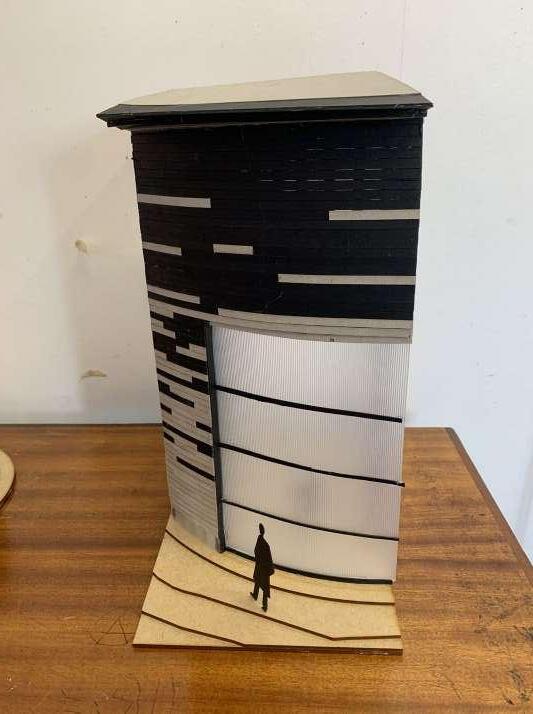
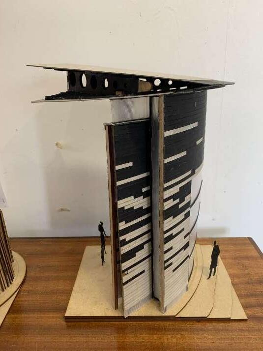
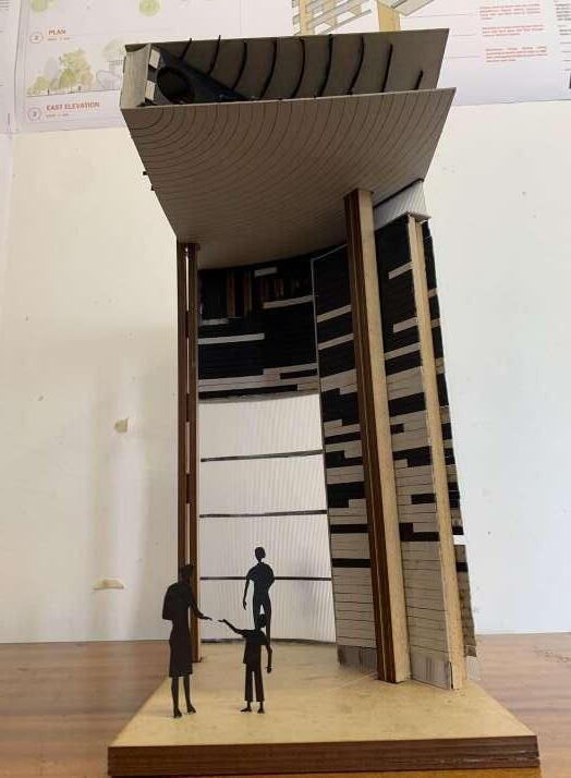
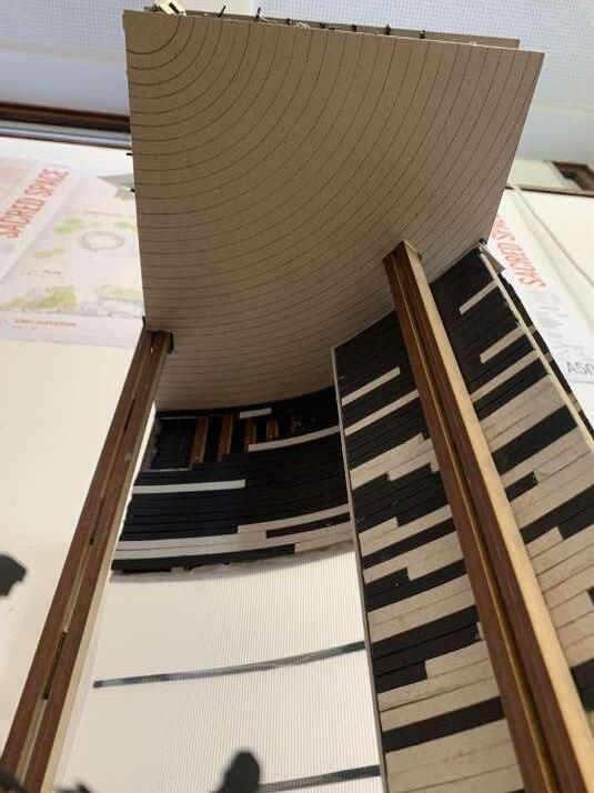
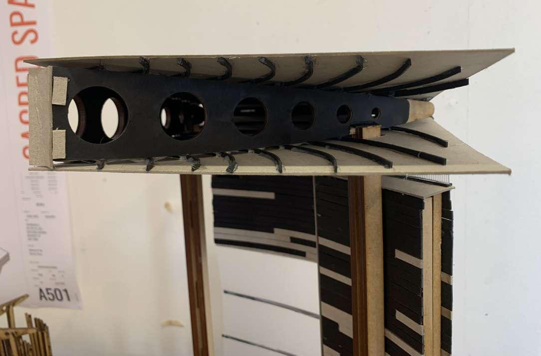
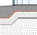
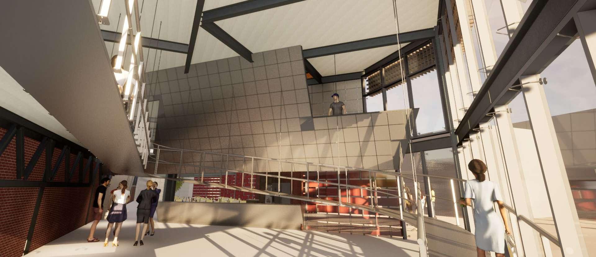
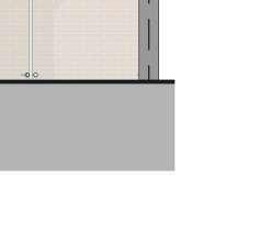
22 1:20 FINAL SECTIONAL MODEL 0.4
PROPOSAL DATA
TYPE: Conceptual design
DATE: 24 July - 25 August 2023
LOCATION Paarden Eiland, Cape town
PROFESSOR Amélie de Bonnières
COLLABORATORS Clint Abrahams
The project focuses on creating a design that optimizes space use, accommodates diverse users, considers cultural and social influences, makes thoughtful material choices, and explores how materials are integrated into the design’s various sections.
This holistic approach ensures that the resulting building is not only functional and aesthetically pleasing but also responsive to the community’s needs and the environment within.
23
0.5
STEEL FRAMEWORK
MASSING BLOCKS CONCEPT
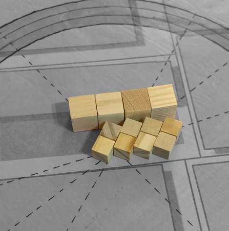
I used timber blocks to experiment and gather ideas of what the general massing of my structure could look like.
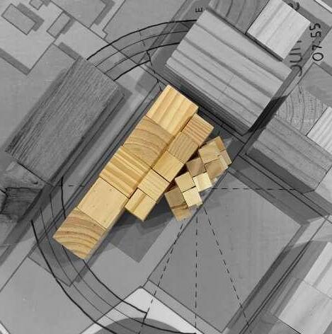
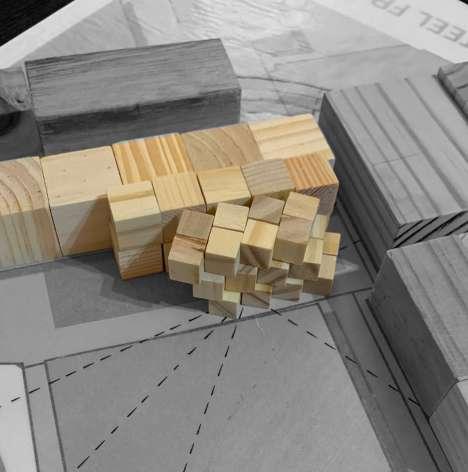
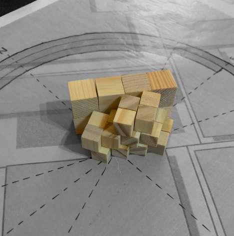
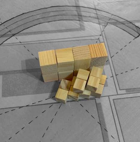
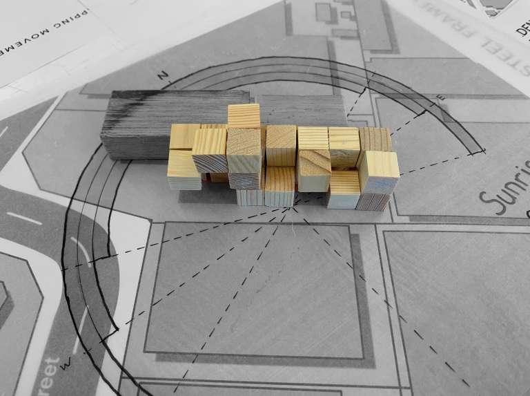
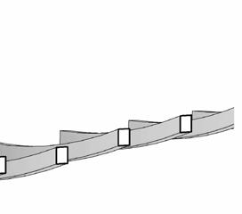
In the first option, I wanted to create a public space at the entrance of my building, similar to what is shown in my second precedent (Centra at Metropark). This was, however, proving difficult to finalise, which led me to my second option.
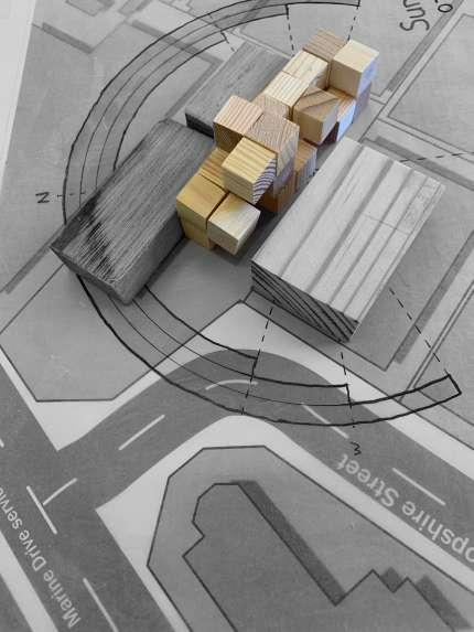
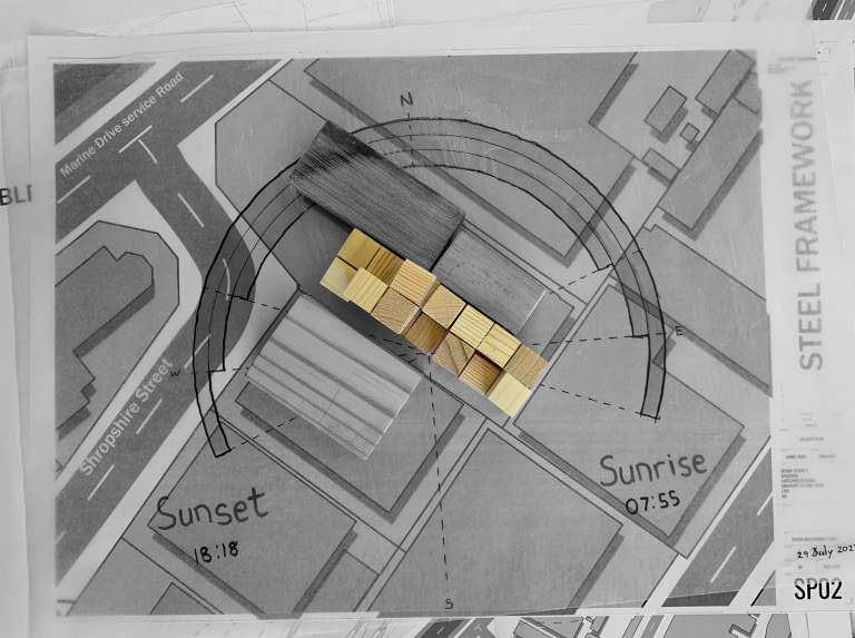
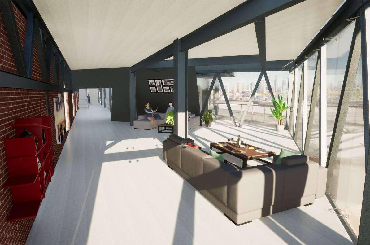
In option 2, the massing consists of two main elements - The circulation corridor and living units staggered from the corridor towards the ocean and city.
The staggering of the units creates the opportunity for an overhanging element in the interior of the building, as you will see later.
0.5
Concept Sketches
Option 02 (Chosen)
Modular experimentation: Sectional analysis Facade ideas: De-constructive exposed steel Stagger experimentation: Allow for more natural light Micro Exercise: Living Unit Linear: Corridor & Circulation Industrial Steel: Bracing frames
Option 01
This unit presented the best layout because it has a more rectangular shape sized at 6x3m.


It also creates an opportunity for inhabitants to move onto a balcony should they want to.


The unit also contains a compact kitchen and bathroom and a timber slat screen that does divide the space between night and day functions.
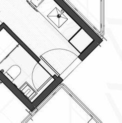
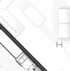
25 P3 P4 TBD P5 P6 Bathroom 2500 110 650 Mirror 850 600 1300 FLOOR PLAN +0.0 CEILING +2750 650 Bar fridge Drawer Bin Dish washer Oven Pantry P1 Extractor Closet Storage Soapstone backsplash 1500 4500 130 900 820 900 1030 1720 P3 P6 P4 P5 SCALE: 1 : 50 3 Bathroom & Dining SCALE: 1 : 50 2 Kitchen Elevation SCALE: 1 : 50 4 Bathroom & Kitchen SCALE: 1 50 5 Dining 110 5 FLOOR PLAN P3 P4 TBD P5 P6 Bathroom Dining 2500 110 1890 650 Mirror 850 600 1300 FLOOR PLAN +0.0 CEILING +2750 650 Bar fridge Drawer Bin Dish washer Oven Pantry P1 Extractor Closet Storage Soapstone backsplash 1500 4500 130 900 820 900 1030 1720 P3 P6 P4 P5 SCALE: 1 : 50 3 Bathroom & Dining SCALE: 1 : 50 2 Kitchen Elevation SCALE: 1 : 50 4 Bathroom & Kitchen SCALE: 1 50 5 Dining 3 2 Bedroom Bathroom BIC Kitchen Pantry P1 P1 P5 P4 P3 P6 TBD 1300 915 785 3000 131 700 1669 110 1990 1400 6000 700 5 4 Dining SCALE: 1:50 1 FLOOR PLAN UNIT A LAYOUTS 0.5
Chosen Unit
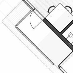
26 1:50 STRUCTURAL
0.5
MODEL
STRUCTURAL EXPLORATION
27
0.5
I-Beam & H-column Structure Welded & bolted connections
Exploded Structural diagram illustrating how the ‘unit boxes’ slot into the bigger framework.
Exploded Diagram illustrating how each unit slots into its “unit box’ structure.


28 6 8 A B 1 C D E F G H Site Boundary Site Boundary Site Boundary 0053 3500 6570 3500 A D E Overhead balcony 1.3 1.2 1.1 Lobby Reception & Coffee counter Entrance Public social Space Swing open Swingopen Swing open Coffee shop seating A A B Market space 6510 4740 3300 6860 10160 Countertop 1:12 Elevator ERF 14709 ERF 17408 ERF 16882 PLANS FINAL DRAWINGS 0.5 Exterior deck Interior balcony Opentobelow Elevator Opentobelow Unit 101 Unit 102 Unit 103 Unit 104 Hallway Opentobelow Opentobelow 1:12 Perforatedsheetmetal Featurewall Opentobelow Opentobelow Unit 201 Unit 202 Unit 203 Unit 104 Hallway Opentobelow Opentobelow Communal space 01 85m2 Balcony Balcony Balcony Balcony 2° 2° 2° 2° Perforatedsheetmetal Featurewall balconyExterior Elevator Opentobelow Opentobelow Unit 301 Unit302 Unit 303 Unit 304 Hallway Opentobelow Opentobelow Communal space 02 85m2 deckExterior Balcony Balcony Balcony Balcony 2° 2° 2° Roof line Roof line lineRoof lineRoof lineRoof lineRoof Roof line Elevator lineRoof 2° IndoorBalcony Open to Below 5° 10° 10° 10° 10° 5° 5° Level 01 Level 02 Level 03 Roof
A major driving force of my design was to encourage relationships between inhabitants of the building. Voids in the floor plane just outside an inhabitant’s door allow them to look down or up through the floor at another person who might also be at their door. This initiative will nurture a more cohesive community within the new development.


Bathroom Kitchen Bed Dining Unit 101 Unit 201 Unit
Balcony Balcony Market Space Coffee shop seating ocean SECTIONS FINAL DRAWINGS 0.5 Views to Ocean SECTION AA 1 SCALE 1 100
301
Level 01 Plan | Showing openings in the floor plane
Section


30 FIN. FLOOR +0.0 +3000
Slanted & perforated steel mesh feature wall
Communal Space 01
are & reception
0.5 SECTION BB 1 SCALE 0m 1m 2m 3m 4m 5m
Communal Space 02
Coffee
SECTIONS FINAL DRAWINGS


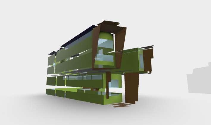
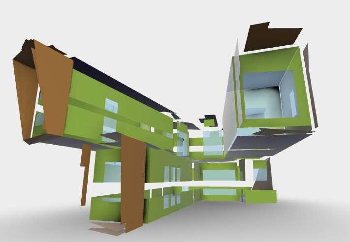
31 ELEVATIONS FINAL DRAWINGS 0.5 SOUTH WEST ELEVATION 1 SCALE 1 200 NORTH WEST ELEVATION 2 SCALE 1 200 EXPLODED AXONOMETRIC 3 SCALE: 00 GROUND 01 FIRST FLOOR 02 SECOND FLOOR 03 THIRD FLOOR 04 ROOF Units are staggered, Not directly above
32
0.5
EXTERIOR & INTERIOR RENDERS
RV3 - Street Perspective
RV1 - Street Perspective
RV4 - Communal Space Level 02
RV2 - Boundary wall Facade
RV2 - Foyer Level 01
PROPOSAL DATA
TYPE: Environmental & services based design


DATE: 26 July - 6 November 2023
LOCATION Othongathi KwaZulu-Natal, South- Africa
PROFESSOR Tom Sonya
COLLABORATORS Matthew Shepherd
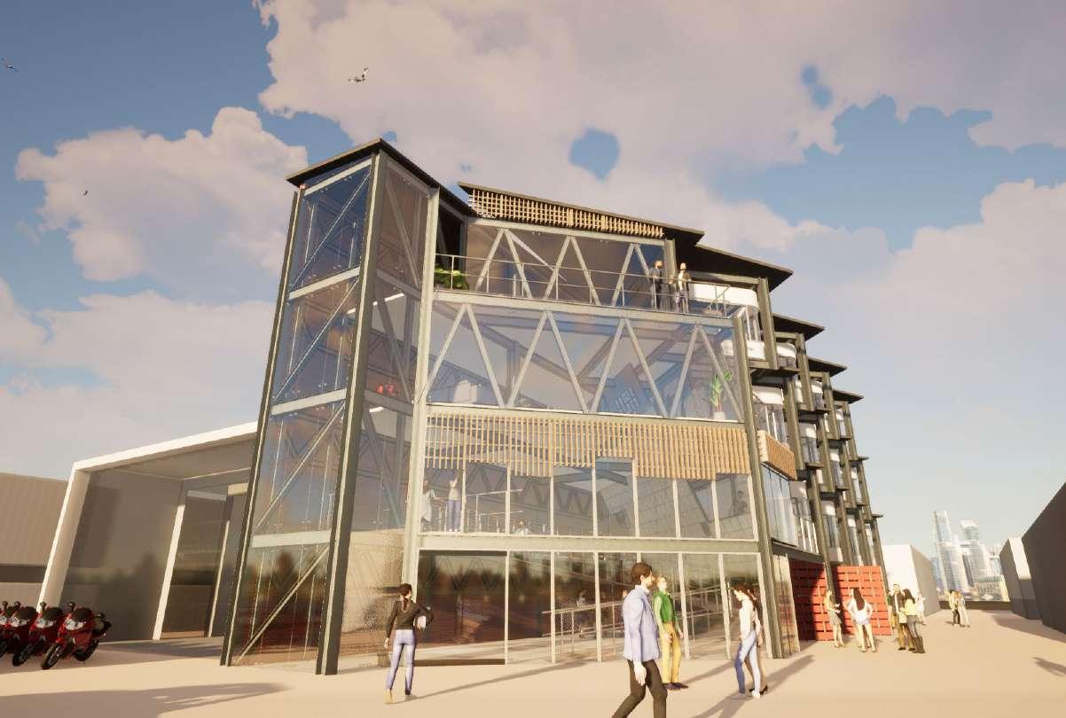
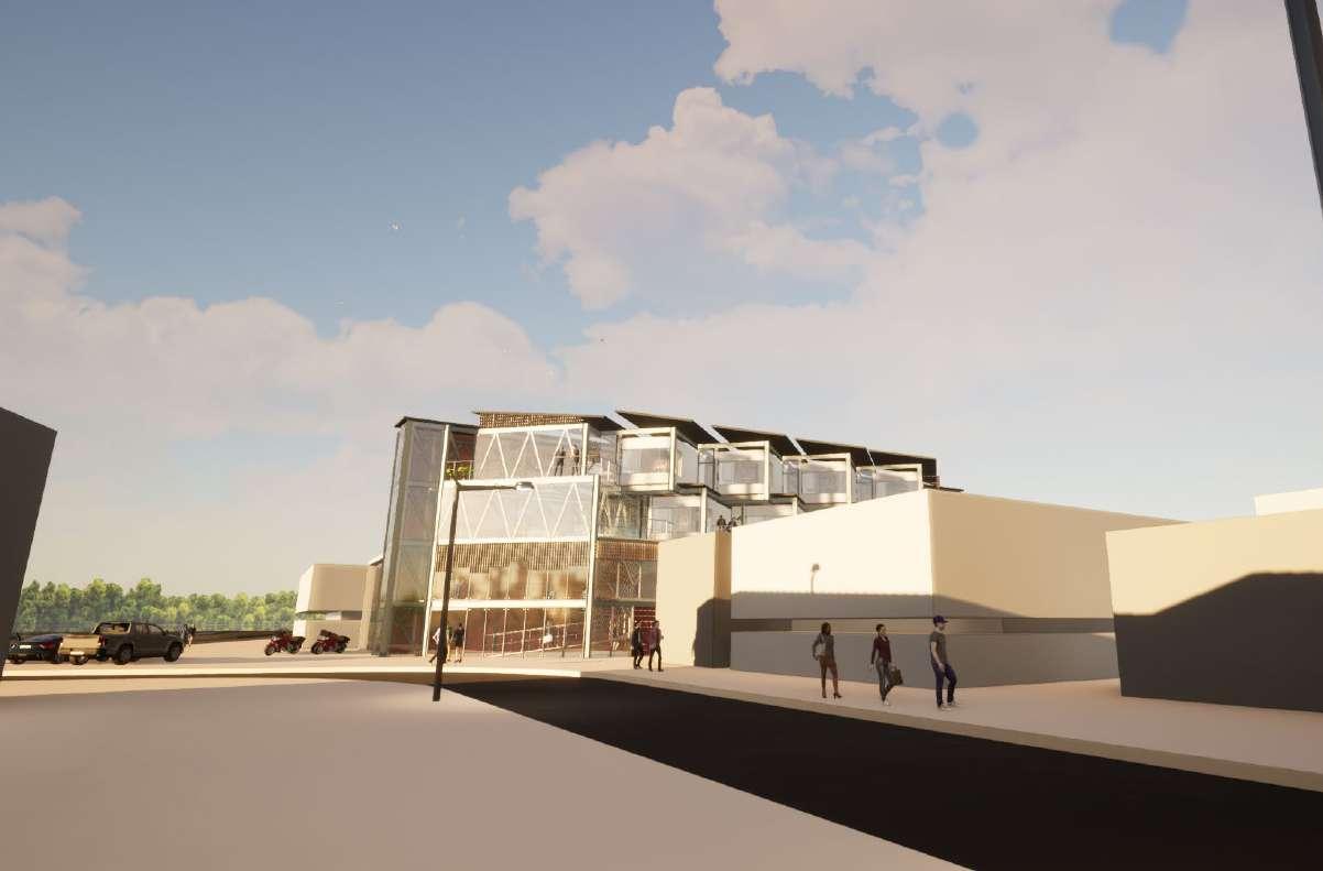
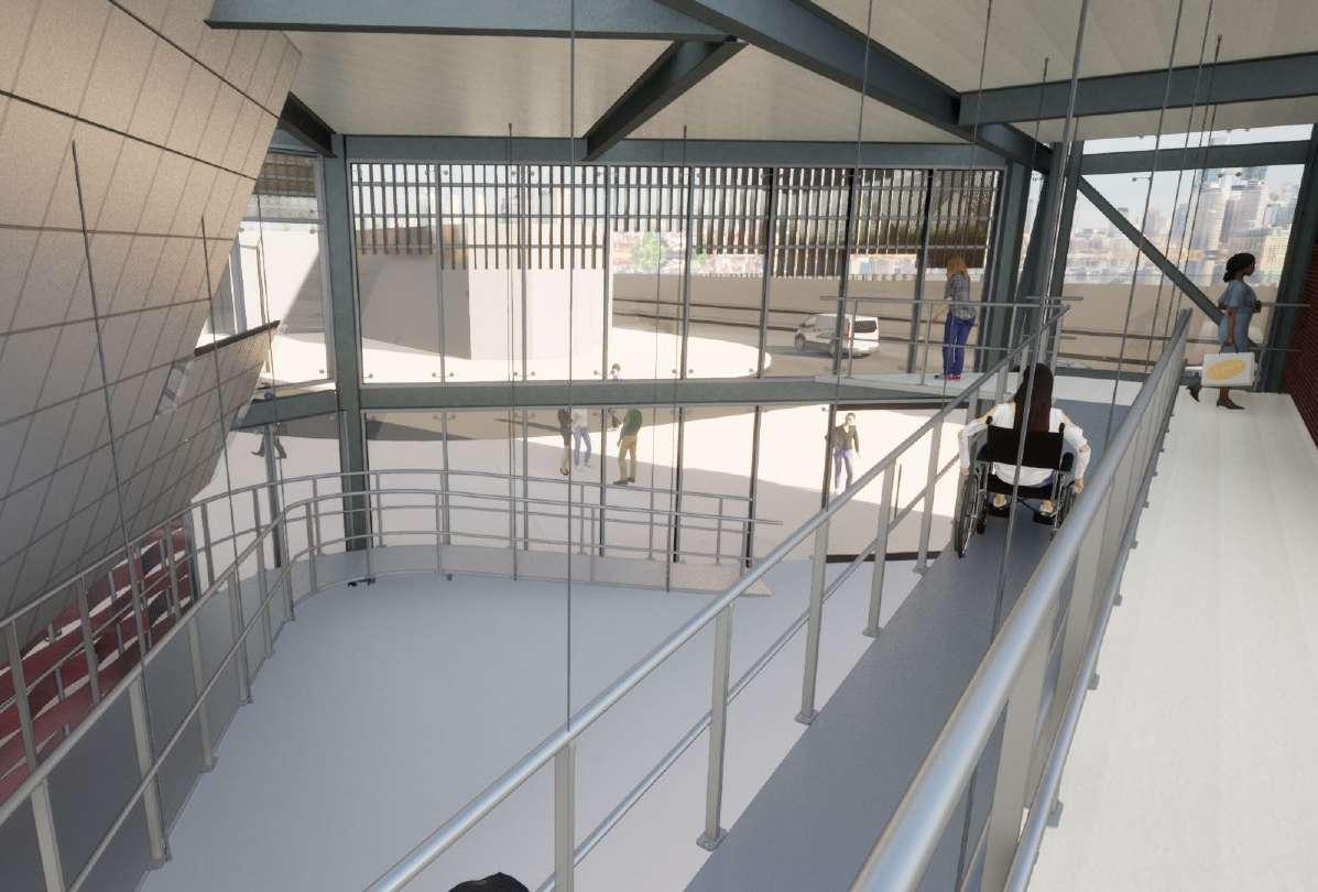
Project X introduced the world of real life building codes and regulations into our design, these strategies are generally not considers in Design Studio II in order to retain creative freedom.
Our environmental & services subject equipped us with all the necessary knowledge to produce a building that adheres to SANS XA regulations, water & energy models as well as a suitable climatic response for the prescribed site..
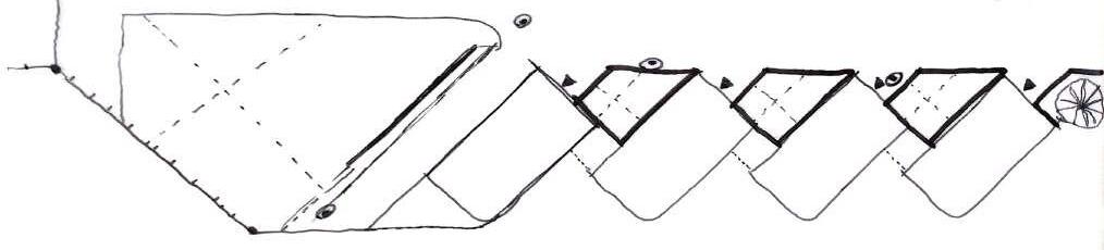
33 PROJECT X 0.6
34 SITE SPECIFIC CLIMATIC RESEARCH 0.6
35 NET ZERO CONCEPT SKETCHES 0.6
Black charred timber
Natural materials with low embodied energy Close proximity to nature Experimental design
OSB Timber panels
Plans Perspective
SMORGASBORD
SECTION AA
SECTION BB
Perspective


36 SITE SPECIFIC FINAL DRAWINGS Deck Washer & Dryer Plantings 5 m² Guest Bedroom/ Study 15 m² Master Bedroom 9 m² En-Suite Opentobelow 2 A201 28 m² Upstairs area 5 m² Guest Bathroom P6 P7 P5 P4 P8 P7 P5 P4 E2 E14 E15 E13 E13 E13 E12 E12 E2 E2 20 m² Upstairs lounge 3 7 3 2 2 2 2 4 5 A201 3 1 A201 2 A201 17 m² Kitchen P2 P1 P3 E1 E2 E3 E5 E6 E10 E11 E11 9 m² Dining 27 m² Living space 2 m² Enterance 3500 12000 3000 3000 5 5 5 5 5 3 3 6 2 4 1 ROOF +600.0 8 1 1 1 7 5° 5° FIN. FLOOR +0.0 LEVEL +300.0 ROOF +600.0 9 5 5 Existing Dwelling Erf 2472 Erf 2470 Erf 2471 Seize: 923m CassiaRoad A301 A301 A301 3000 3000 5° [No Slope] 5° 5° 5° Driveway 3500 12000 3mCommon setbackline 3mCommon setbackline 3.5mStreetsetbackline 12mStreetsetbackline Ground Floor Plan 1 SCALE 100 West Elevation 4 SCALE 100 First Floor Plan 2 SCALE 1 : 100 North Elevation 5 SCALE 1 : 100 East Elevation 6 SCALE 1 100 Site Plan 3 SCALE 1 500
when developing the Mora One was the classical outdoor water pump. Mora One has the same conical body and sharp transitions to the flat surfaces as an old water pump. Mora One has an advanced and reliable technique. The mixers are contributing to a more sustainable environment by saving as much water and energy as possible without compromising on comfort.
Article number: 262051
Description: Chrome
Ceramic cartridge with soft closing function
Adjustable flow control and temperature limiter
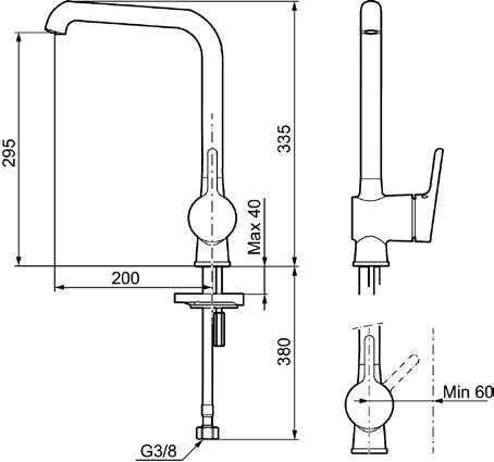
®
Soft PEX hoses with 3/8" connecting nut (stainless steel braided)
Swivel spout, limitation part for 60°, 85°, 110° or 360° included
Hole diameter Ø34-37 mm
Water
Requirements
Uniqe characteristics
Energy class
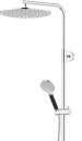
MORA INXX II shower system kit
With its durable chrome finish the INXX II combines classic design with high performance, constant temperature, outstanding comfort and effective scald protection. The overhead shower has a large, slim shower head that looks great in bathrooms with a strong character and striking shapes, as well as in classic bathrooms designed for rest and relaxation. The mixer has been tested and approved according to current building regulations and is energyefficient, which means it reduces water and energy use without compromising on comfort. The INXX II collection offers a world-class water experience.
About the collection INXX II is an elegant, timeless collection in a palette of carefully selected colours. Offering a combination of high quality, sober design and outstanding comfort, this is the ultimate collection.
Article number: 271800
Description: Chrome, 160 c/c
Consist of: MORA INXX II thermostatic mixer:
Pressure balanced thermostatic mixer
• With reversible headwork
• Temperature handle with safety stop at 38°C
• With Eco-function Approved non-return valves, EN-Standard EN1717
MORA INXX II Shower System:

• Shower hose in metal, PVC- and BPA-free
With Easy-Clean anti-limescale system
• Adjustable height
• Hand shower 7,5 l/min, shower head 11 l/min
37
0.6 2025 900 597,6 450 389,88 337,5 259,92 107,5687,1712 2,208
of water used Per household sanitaryware per year Wash Basin (Guest Bathroom) Wash Basin (En Suite) Outdoor tap Shower (En Suite) Toilet (Guest Bathroom) Shower (Guest Bathroom) Toilet (En Suite) Sink Washing Machiene Dish Washer Units Flow rate [B] Units Kitchen P1 Sink 11,7 P3 Dish Washer 11,6 En Suite Bath P4 Shower 11,31 P5 Toilet 6,06 P7 Wash Basin Mixer 7,8 Guest Bathroom P4 Shower 11,31 P5 Toilet 6,06 P7 Wash Basin Mixer 7,8 P9 Washing Machine 86 Other Outdoor tap 8,3 Totals 167,94 Water Requirements Time per used [C] Total per use [D=B*C] Number of uses per day [E] min (or unit) litres 2 23,4 12 3 34,8 1 10 113,1 1 1 6,06 8 2 15,6 10 10 113,1 1 1 6,06 8 2 15,6 10 2 172 1 20 166 1 53 665,72 53 Water Number of users [F] Total per day [G=D*E*F] Days per month [H] litres days 3 842,4 25 1 34,8 12 3 339,3 25 3 145,44 25 3 468 25 3 339,3 25 3 145,44 25 3 468 25 1 172 12 5 830 20 28 3784,68 219 Requirements Total per month [I=G*H] Months per year [J] Total per year [K=I*J] litres litres 21060 12 252720 417,6 12 5011,2 8482,5 12 101790 3636 12 43632 11700 12 140400 8482,5 12 101790 3636 12 43632 11700 12 140400 2064 12 24768 16600 12 199200 87778,6 120 1053343,2
WATER & ELECTRICITY USAGE ANALYSIS
Liters
Qty as M^3 [L=K/1000] Recycleable [M] Requires potable water (m^3) [N] m^3 m^3 m^3 252,72 5,01 101,79 43,63 140,40 101,79 43,63 140,40 24,77 199,20 1053,34 0 0
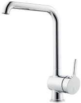
Rainwater calcs Othongathi Jan Rainfall mm 120 Roof area m2(constant) 120,61 Potential water capture (litres) 11400 Actual water capture (90%) 10260 Actual water captured in m3 10,26 Feb Mar Apr 130 115 90 120,61 120,61 120,61 12350 10925 8550 11115 9832,5 7695 11,115 9,8325 7,695 May Jun Jul 60 35 25 120,61 120,61 120,61 5700 3325 2375 5130 2992,5 2137,5 5,13 2,9925 2,1375 Aug Sep Oct 40 65 85 120,61 120,61 120,61 3800 6175 8075 3420 5557,5 7267,5 3,42 5,5575 7,2675 Nov Dec 120 125 120,61 120,61 11400 11875 10260 10687,5 86355 10,26 10,6875 86,355 TOTAL (litres) TOTAL (m3) Uniqe characteristics Backflow protection unit type MORA ONE kitchen mixer Mora One is an elegant and strict series of mixers expressing usability, beauty and durability. Mora One is inspired by the 90-year old history of Mora Armatur, but is designed for a modern home. An inspiration to Thomas Sandell, architect and designer,
1 av 1
1 av 1
I believe it is important to replicate real world conditions as best possible. These images on the left are plumbing fixture taken from manufacturer’s website , they provide all the needed sizes and flow rates for my self to make informed decisions and accurate calculations in my project.
WATER & ELECTRICITY USAGE ANALYSIS
Electricity Requirements
I again compiled information for manufacturer’s almost endless catalogues of lighting fixtures to best suite the scheme and need of lighting in my building. Wattage values and quantities are read into the Excel sheet as well as other variables.
38
0.6 Appliance No. of appliances Power demand (W) Appliance N P Kitchen E1 Dish Washer 1 2500 E2 Kettle 1 2400 E3 Cooktop 1 E4 Extractor Fan 1 248 E5 Microwave oven 1 3000 E6 Fridge w freezer 1 100 E7 Pendent Lights 4 15 E8 LED Downlights 3 7 E9 LED Under shelf Strip Lighting 2 17,39 Lounge E10 TV 1 318 E8 LED Downlights 13 7 E11 Floor lights 2 15 E12 Pendent Lights Long 3 15 Bed & En suite 1 E8 LED Downlights 10 7 E13 Bedstand lights 2 15 Upstairs Living E8 LED Downlights 5 7 Bedroom 2 & Bathroom 2 E8 LED Downlights 8 7 E14 Washer 1 3000 E15 Dryer 1 5000 Upstair reading Nook E8 LED Downlighs 10 7 E7 Reading light 1 80 Utilities & Exterior E16 Geyser (solar electric backup) 1 2600 E8 External LED downlights 8 7 E17 External Feature lights 3 30 TOTAL (Wh) TOTAL (KWh) Electricty energy production
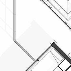
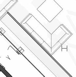
Solar Thermal (ST) Hours switched on Consumption per day Days/ Annum Consumption/ Note H C = N*P*H (Wh) D C/A = C *D (Wh) Note 1,1 2750 104 286000 0,3 720 365 262800 0,3 0 365 0 19kg AFROX Gass 0,3 74,4 365 27156 1 3000 200 600000 4 400 330 132000 3 180 365 65700 3 63 365 22995 8 278,17 365 101532 4,8W/meter 8 2544 300 763200 3 273 300 81900 3 90 300 27000 2 90 360 32400 3 210 365 76650 2 60 365 21900 3 105 330 34650 4 224 365 81760 1 3000 82 246000 1 5000 51 255000 4 280 365 102200 3 240 200 48000 1 2600 340 884000 3 168 301 50568 8 720 302 217440 3866843 Wh 3867 KWh 322 KWh 11 KWh Location oThongathi KWh/KWp/d 3,87 KWh Consumption/day 11 KWh KWp required 2,74 KWp Module area 1,95 sqm Module power rating (Wp) 350 Wp Module power rating (KWp) 0,35 KWp 7,82 modules 15,25 sqm Average daily consumpiton Average monthly consumption Number of modules required required Tolal area of modules required No. of inhabitants 3 Hotwater requirement/ pp 60 litres Hotwater tank size 180 litres ST panel/pp 0,7 sqm Total ST panel area 2,1 sqm Axonometric- Electrical conduit layout
Schedule- Sizes
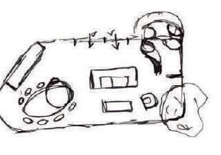
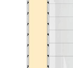
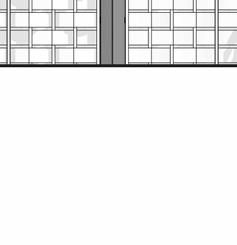
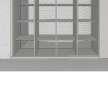
39 SANS XA GLAZING
0.6
& openings Window Schedule- Sizes & glazing types & openings Window Schedule- Sizes & glazing types & openings Analytical Spaces Window Sectional view Window Number Quantity Catalogue Number Frame Finish Glazing Ironometry Aluminum Top hung Friction Stays. Plugged, screwed and sealed to brickwork or concrete, in accordance with AAAMSA Selection Guide for Glazed Aluminum Architectural Aluminum Products June 2008. 6.38mm clear glass including clip-on glazing beads with neoprene seals. Glazing shall be executed strictly in conformance with glass manufacturer`s recommendations and SANS 10137:2011 all in accordance with SANS 10400 Parts B, N, XA. Surfaces to receive 60-80μ Charcoal powder coating (for architectural applications), supplied by manufacturer complying with SANS 1578 and applied in accordance with SANS 1796 by an approved applicator. Aluminum Skylight overall size 1060 1060mm able to meet the mechanical performance requirements of SANSA 613. Plugged or screwed to brickwork. Sill inside Sill outside Location FFL Lintel Height Window Sectional view CL PS1215L W1 Window Number Quantity Catalogue Number Frame Finish Glazing Ironometry 1 Aluminum Top hung Friction Stays. Plugged, screwed and sealed to brickwork or concrete, in accordance with AAAMSA Selection Guide for Glazed Aluminum Architectural Aluminum Products June 2008. 6.38mm clear glass including clip-on glazing beads with neoprene seals. Glazing shall be executed strictly in conformance with glass manufacturer`s recommendations and SANS 10137:2011 all in accordance with SANS 10400 Parts B, N, XA. Surfaces to receive 60-80 m Charcoal powder coating (for architectural applications), supplied by manufacturer complying with SANS 1578 and applied in accordance with SANS 1796 by an approved applicator. Aluminum Skylight overall size 1060 1060mm able to meet the mechanical performance requirements of SANSA 613. Plugged or screwed to brickwork. Sill inside Sill outside Location 2100 CL 1 24DT18 W2 Window Number Quantity Catalogue Number Frame Finish Glazing Ironometry Aluminum Top hung Friction Stays. Plugged, screwed and sealed to brickwork or concrete, in accordance with AAAMSA Selection Guide for Glazed Aluminum Architectural Aluminum Products June 2008. 6.38mm clear glass including clip-on glazing beads with neoprene seals. Glazing shall be executed strictly in conformance with glass manufacturer`s recommendations and SANS 10137:2011 all in accordance with SANS 10400 Parts B, N, XA. Surfaces to receive 60-80μm Charcoal powder coating (for architectural applications), supplied by manufacturer complying with SANS 1578 and applied in accordance with SANS 1796 by an approved applicator. Aluminum Skylight overall size 1060 1060mm able to meet the mechanical performance requirements of SANSA 613. Plugged or screwed to brickwork. Sill inside Sill outside Location 2100 CL 6T18 W3 Window Number Quantity Catalogue Number Frame Finish Glazing Ironometry Aluminum Top hung Friction Stays. Plugged, screwed and sealed to brickwork or concrete, in accordance with AAAMSA Selection Guide for Glazed Aluminum Architectural Aluminum Products June 2008. 6.38mm clear glass including clip-on glazing beads with neoprene seals. Glazing shall be executed strictly in conformance with glass manufacturer`s recommendations and SANS 10137:2011 all in accordance with SANS 10400 Parts B, N, XA. Surfaces to receive 60-80μm Charcoal powder coating (for architectural applications), supplied by manufacturer complying with SANS 1578 and applied in accordance with SANS 1796 by an approved applicator. Aluminum Skylight overall size 1060 1060mm able to meet the mechanical performance requirements of SANSA 613. Plugged or screwed to brickwork. Sill inside Sill outside Location _3000 CL-Window Number Quantity Catalogue Number Frame Finish Glazing Ironometry Aluminum Top hung Friction Stays. Plugged, screwed and sealed to brickwork or concrete, in accordance with AAAMSA Selection Guide for Glazed Aluminum Architectural Aluminum Products June 2008. 6.38mm clear glass including clip-on glazing beads with neoprene seals. Glazing shall be executed strictly in conformance with glass manufacturer`s recommendations and SANS 10137:2011 all in accordance with SANS 10400 Parts B, N, XA. Surfaces to receive 60-80μm Charcoal powder coating (for architectural applications), supplied by manufacturer complying with SANS 1578 and applied in accordance with SANS 1796 by an approved applicator. Aluminum Skylight overall size 1060 1060mm able to meet the mechanical performance requirements of SANSA 613. Plugged or screwed to brickwork. Sill inside Sill outside Location 2100 CL PS129R W9 Window Number Quantity Catalogue Number Frame Finish Glazing Ironometry 1 Aluminum Top hung Friction Stays. Plugged, screwed and sealed to brickwork or concrete, in accordance with AAAMSA Selection Guide for Glazed Aluminum Architectural Aluminum Products June 2008. 6.38mm clear glass including clip-on glazing beads with neoprene seals. Glazing shall be executed strictly in conformance with glass manufacturer`s recommendations and SANS 10137:2011 all in accordance with SANS 10400 Parts B, N, XA. Surfaces to receive 60-80 m Charcoal powder coating (for architectural applications), supplied by manufacturer complying with SANS 1578 and applied in accordance with SANS 1796 by an approved applicator. Aluminum Skylight overall size 1060 1060mm able to meet the mechanical performance requirements of SANSA 613. Plugged or screwed to brickwork. Sill inside Sill outside Location 2650 CL 10 15T45R W5 Window Number Quantity Catalogue Number Frame Finish Glazing Ironometry Aluminum Top hung Friction Stays. Plugged, screwed and sealed to brickwork or concrete, in accordance with AAAMSA Selection Guide for Glazed Aluminum Architectural Aluminum Products June 2008. 6.38mm clear glass including clip-on glazing beads with neoprene seals. Glazing shall be executed strictly in conformance with glass manufacturer`s recommendations and SANS 10137:2011 all in accordance with SANS 10400 Parts B, N, XA. Surfaces to receive 60-80μ Charcoal powder coating (for architectural applications), supplied by manufacturer complying with SANS 1578 and applied in accordance with SANS 1796 by an approved applicator. Aluminum Skylight overall size 1060 1060mm able to meet the mechanical performance requirements of SANSA 613. Plugged or screwed to brickwork. Sill inside Sill outside Location 1500 600 15T15R W4 Window Number Quantity Catalogue Number Frame Finish Glazing Ironometry Aluminum Top hung Friction Stays. Plugged, screwed and sealed to brickwork or concrete, in accordance with AAAMSA Selection Guide for Glazed Aluminum Architectural Aluminum Products June 2008. 6.38mm clear glass including clip-on glazing beads with neoprene seals. Glazing shall be executed strictly in conformance with glass manufacturer`s recommendations and SANS 10137:2011 all in accordance with SANS 10400 Parts B, N, XA. Surfaces to receive 60-80μ Charcoal powder coating (for architectural applications), supplied by manufacturer complying with SANS 1578 and applied in accordance with SANS 1796 by an approved applicator. Aluminum Skylight overall size 1060 1060mm able to meet the mechanical performance requirements of SANSA 613. Plugged or screwed to brickwork. Sill inside Sill outside Location 2100 18T18L W7 Window Number Quantity Catalogue Number Frame Finish Glazing Ironometry 1 Aluminum Top hung Friction Stays. Plugged, screwed and sealed to brickwork or concrete, in accordance with AAAMSA Selection Guide for Glazed Aluminum Architectural Aluminum Products June 2008. 6.38mm clear glass including clip-on glazing beads with neoprene seals. Glazing shall be executed strictly in conformance with glass manufacturer`s recommendations and SANS 10137:2011 all in accordance with SANS 10400 Parts B, N, XA. Surfaces to receive 60-80 m Charcoal powder coating (for architectural applications), supplied by manufacturer complying with SANS 1578 and applied in accordance with SANS 1796 by an approved applicator. Aluminum Skylight overall size 1060 1060mm able to meet the mechanical performance requirements of SANSA 613. Plugged or screwed to brickwork. Sill inside Sill outside Location 2100 CL 1 6T11 W8 FFL Lintel Height FFL Lintel Height 1800 300 614 1172 614 2400 1800 300 592 17 583 22 586 600 592 16 584 308 600 888 611 1500 CL 450 2200 808 570 22 1400 22 770 308 1000 22 570 22 1186 1800 21 570 16 584 22 585 300 CL 900 1100 608 570 22 1200 1500 600 1200 570 608 1110 600 1100
& FENESTRATION
Window
& glazing types
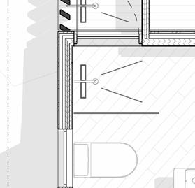
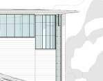
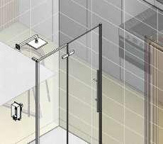
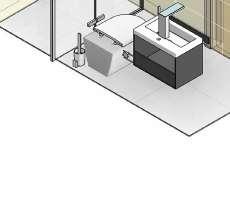
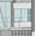
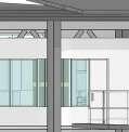
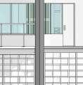
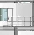
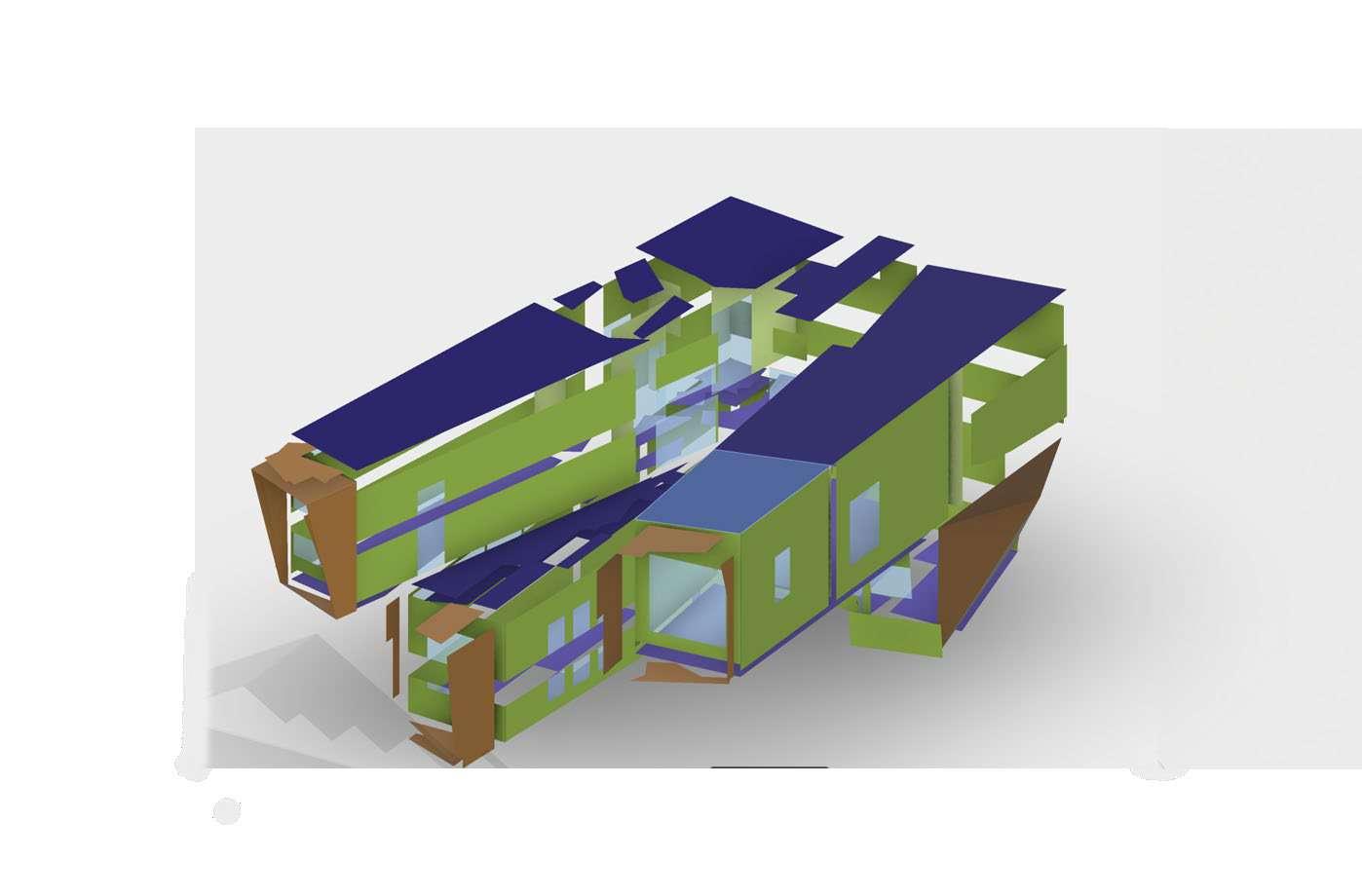
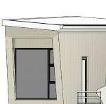
APARTMENT ORBAN BROOKLYN, NEW YORK
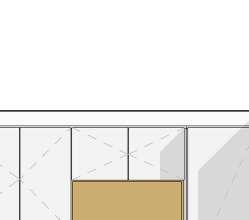
The client owns a loft in Brooklyn, New York. He is looking to sell the space, so he requested that we model up the apartment and add the changes he requested to possible boost the value. These additions included a second bedroom on the ground floor,as well as a Built In Closet.
I was thrilled to work on a project outside of South Africa. Hopefully there are many more to come.

THREE STUDIO 21
THREE STUDIO 21
As-Built Revit drawings of the apartment with some rough measurements provided by the clients PDF drawings.


top


40 HESTER-STEPH ARCHITECTS 0.7 Drawn by Date
Cindi Janse van Vuuren cindi@studiothree21.co.za 2023/08/17 10:49:35 Glencairn Village Patric Orban Cindi JvV A01 Perspective A Apartment 6J, 330 Whyte Street, New York, NY. Lounge Perspective 1
Interior
the apartment Drawn by Date
Joinery drawings of the proposed Built In Closet that sits below and on
of the Loft level.
views of
Cindi Janse van Vuuren cindi@studiothree21.co.za 2023/08/17 10:49:39 Glencairn Village Patric Orban Cindi JvV A02 Perspective B Apartment 6J, 330 Whyte Street, New York, NY. Kitchen -Perspective 1 A101 Existing BIC be removed. Make good trades. Kitchen Dining Area Lounge Proposed Bedroom Guest Bathroom APARTMENT New 4x8 flexible birch plywood sheets, concelead fixed 3x6 timber fins strut support columns. Wood Veneer Exterior Doors Interior panels: Dark gray masonite or painted Loft Exiting railings to be demolished shower New joinery acc. detail -- Celing 17.8 Fixed panel WDOpen shelves Bottom Recess -- Celing 17.8 Exst Concrete beam column Vertical member painted 1/2") Open shelves be painted acc. client spec (22 1/2" deep) WD-01 Door (28") 10.00" 32.50" 32.50" 32.50" 32.50" 3.00" ified otherwise. HESTER STEPH Drawing Title: THREE STUDIO 21 Cindi Janse van Vuuren cindi@studiothree21.co.za 50 Three21\PROJECTS\Apartment Orban (New York) Waiti on Client Brief\REVIT\Apartment Orban.rvt 2023/08/17 10:47:07 HS Potgieter Pr.Arch 22170 01 A101 Patric Orban Apartment 6J, 330 Whyte Street, New York, NY. Plans 12/08/22 Stage 50 00 -Floor Plan -6th Floor 3 50 01 -Mezz 4 50 Elevation 2 2 50 Section 1 1 Pantry Perspective 5 Mezz -Perspective 6 Fixed Fixed Fixed Fixed Wood Veneer Fixed Panels WDDOOR NO 28" 3" Base painted (Recessed panel) 28.00" 38.08" 38.08" 38.08" 2.2 0.1 0.1 2.2 0.1 2.2A401open shelves hanging bar void -02 - Celing 17.8SHELVES SHELVES HANGING BAR WDDOOR WDDOOR WDDOOR WDDOOR Open Shelves painted charcoal grey, colour TBC 22 1/2" deep WDDOOR NO 28" Base painted Recess panel Fixed WD - Panel This drawing the property copyright. A: building work to comply with S.A.N.S. 104 B: Figured dimensions are taken only. C: This drawing be scaled. D: levels shown are finished levels unless spec E: discrepancies and errors must reported NOTES: Drawing Title: Building occupancy: Zoning: STUDIO 21 Cindi Janse van Vuuren cindi@studiothree21.co.za 1/2" 1' Three21\PROJECTS\Apartment Orban (New York) Waiti Brief\REVIT\Apartment Orban.rvt HS Potgieter Pr.Arch 22170 01 12/08/22 Stage 1/2" = 1'-0" Elevation Back 2 1/2" = 1'-0" Plan-Lower 3 1/2" = 1'-0" Plan -Upper 4 3D Ortho 5 3D Ortho 2 6 Interior Panels: Dak Gray masonite or painted. WDOakwood Italian Oyster Quatered Ash D5I 9230 WDMillwork doors and panels to be oak veneer, 1/2" = 1'-0" Elevation Front -WD1 1


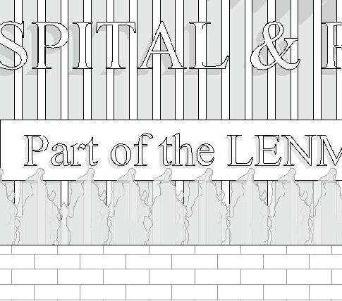


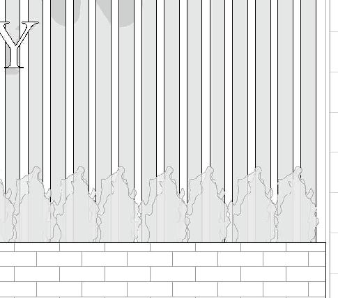


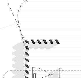
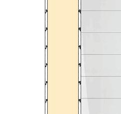
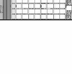
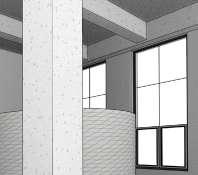
41 DESIGNED & CONSTRUCTED 0.8 6000 2900 835 53units of 75x75x2400mm Square Tubing 600x500x6000m m Brick Wall Stainless steel/ Aluminium Leaf 50units of 38x100x500 mm slats 1950 1025 3000 1926 597 320 300 250 230 800 800 200 "MooiMED" in 600mm Times New Roman "HOSPITAL & PHARMACY" in 230mm Times New Roman 75 150 75 "Part of the LYNMED GROUP" in 150mm Times New Roman 1 A103 60 4930 1010 475 4101 1375 2 A102 SCALE: SHEET SIZE: PROJECT NO: ARCHITECT: O S O 3 SIGN TEL: 076 877 0999 20 A101 Elevation 05 Issue Date For Construction 12/08/22 Author Mooi Med Hospital Elevation 1 Elevation 1 28 March 2023 01 Potchefstroom 06/05/2023 Proposed sign Proposed smoking area Completed Project Street Elevation Sign Under construction Completed sign 1 A B D 3 2 3459 A201 1 4596 3610 2223 2223 4445 1730 1730 PLAN 1:20 A101SMO K E AREA Level 0 Level 2400 A B D A201 300 2000 100 230 4060 230 2223 2223 4445 A301SMO K E AREA 1 ELEVATION 2 1:20 A Lip Channel Square tubing Level 1 75x75x2mm Square tubing 75x50x2mm Lip channel 75 75 1655 4370 x95 x3 x2 75x50mm Lip Channel 75x50mm Lip Channel 75x50mm Lip Channel x99 100x38mm Slats 75x75mm Square Tubing A401FOUNDATION 1:5 SMO K E AREA A4022531 STRUCTURE SMO K E AREA
42