
1
& PORTFOLIO INTERNSHIP 0.1 MAY 2024
LIONEL MOSS CV
INTERNSHIP | GALLAGHER LOURENS ARCHITECTS | 2023
In the June holiday, spent three weeks in the offices of Gallagher Lourens Architects, Cape Town. My role included collaborating with Reddy Architects & Urban Planners based in Ireland for the remodelling of a community centre in Ladybridge. additionally contributed to a medical facility in the form of room data sheets in Autodesk Revit.
REMOTE WORK | HS Architects | 2022 - CURRENT (1yr 5m)
My initial role required me to produce As-Built Drawings of existing houses in preparation for renovations or additions. More recently, I have been given more responsibilities, which include sketch designs, council drawings and application forms.
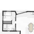
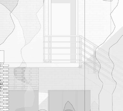
My most exciting project is the proposal for a apartment renovation in Brooklyn, New York.
FREELANCE | MOOIMED HOSPITAL | 2021 2023
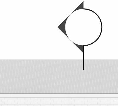
have assisted in the design of several additions to a hospital in Potchefstroom, North West. The most recent projects includes designing a sign at a busy intersection to advertise the hospital.
EDUCATION
UNIVERSITY OF CAPE TOWN | B. ARCH | 2022 CURRENT
Dean’s Merit List 2023 (85.86% Average)
Lisa Blane Memorial Prize winner 2023 Design & Theory Studio 87% Technology 80% Theory of structures II 98% Theory of structures IV 90% Environmental & Services II 91% History & Theory of Architecture II 76% History & Theory of Architecture IV 76%
Golden Key Member 2022
Dean’s Merit List 2022 (86,5% Average)
Design & Theory Studio 90%
Representation 86%
Technology 85%
History & Theory of Architecture I 80%
History & Theory of Architecture II 76%
FERDINAND POSTMA HIGH SCHOOL | NSC |2017 2021
- 4 Distinctions in Metric
- Highest Average for EGD in the North West Province
- I was awarded the Most versatile student award, performing exceptionally on academic, leadership, sport and cultural levels.
- Sports Boy of the Year for three years (2019-2021)
EXPERIENCE PROFILE SOFTWARE COURSES REFERENCES HOBBIES
SSISA Swimming team | 2022- 2023
UCT Swimming team | 2022 Current (2y 9m)
am fortunate to be one of 65 students who form part of the University of Cape Town’s 3rd-year architecture program.
am passionate about my work, set high standards for myself and always on the lookout to improve.
Architecture is integrated into numerous aspects of life, which made me realise that want to contribute to the built environment and feelings that spaces are able to create for people who experience them.
This passion inspires me daily to dive deeper into the innovation aspect regarding architecture the how and why a space is designed in the way it is.
COVER LETTER


21 September 2023
May 2024
All Projects in this portfolio was modelled in REVIT and rendered in LUMION
AutoDesk Revit
Used since 2020. Main modelling software, all projects in portfolio was created using Revit 2022
SketchUp Used since 2019
Autodesk AutoCAD
Used since 2019 with Revit workflow.
Lumion
Adobe Illustrator
Used since 2022, graphical illustration & vector diagrams
Adobe Photoshop
Used since 2021 for post processing
Adobe InDesign
Used since 2022 to compile and design portfolio & presentation boards
Office Suite Proficient in Word/Excel
LinkedIn Learning Autodesk AutoCAD Essential training (9 hours 48 min)
LinkedIn Learning Autodesk Revit Essential training (15 hours)
LinkedIn Learning SketchUp Essential training (2 hours 48 min)
Lumion Essential Training (5h55min)
To whom this may concern
I am writing to express my strong interest in the Internship opportunity at SAOTA. As a dedicated and ambitious Bachelor of Architecture student at the University of Cape Town, I am enthusiastic about the prospect of contributing my skills and passion for architecture to your esteemed firm. With my high academic record, combined with a deep-seated commitment to innovation and design excellence, I am confident that can make a meaningful impact at SAOTA
I am not only academically inclined but also committed to practical experience. I have had the opportunity to work at two architectural firms in Cape Town, where gained valuable insights into the day-to-day operations of an architecture firm, including design processes, project management, and client interactions. This experience has given me a taste of the real-world challenges and opportunities in the field of architecture.
As a intern at SAOTA, I am eager to not only continue my academic journey but also contribute to your team’s creative and innovative projects. I believe that a internship from SAOTA would proved to be a good investment going forward as expressed by some quotes form my reference letters below:
“Lionel has shown a good temperament working under pressure and works well in a group often taking up a leadership role. With his congenial personality and composed leadership, he has successfully dealt with the complex dynamics of group work with his contributions proving invaluable to his team.” - Clint Abrahams
“Lionel is a punctual and positive and active participant in class. His drive, attitude and nascent sustainable design skills make him an excellent addition to any relevant work or study environment” - Tom Sanya
“Lionel has over the course of the year demonstrated not only skill and understanding of making he has also shown an aptitude and work ethic that has allowed for him to stand out within all three studios.” - Dr Philippa Tumubweinee
I look forward to the possibility of discussing my application further in an interview. Please feel free to contact me through the details provided below to schedule an interview at your convenience. Thank you for your time and consideration.
Kind regards
Dr Philippa Tumubweinee philippa.tumubweinee@uct.ac.za
Dr Tom Sonya tom.sonya@@uct.ac.za
Clint Abrahams clint.abrahams@uct.ac.za

Letter of recommendation for Lionel Moss
Dear Sir/Madam
Lionel stands out as a driven, exemplary and openminded student.
met Lionel in 2023 as his lecturer for the Environment and Services course in the second year of the Bachelor of Architectural Studies (BAS) programme at University of Cape Town (UCT). The Environment and Services course focus on the functional, technical, material, and aesthetic integration of sustainable technologies into the built environment – including using sustainability as a design driver. It is this course that first introduces the students to sustainable building design.
Lionel work exhibits a combination of exploration, technical rigour and innovation. The focus of the first half of the academic year was demonstration of understanding of sustainable design theory through building case study analysis. His three-person team studied the Allan Gray Building – a leading sustainable building in Cape Town. In the second semester focus was on environmental design synthesis on a local site in South Africa – including demonstration of fulfilment of the revised SANS 10400XA regulations for energy efficiency – in the Zero X House project. Lionel’s progress in this project from site analysis, through conceptualisation and sketchdesign, and now coming into design finalisation and technical refinement is remarkable. His progress so far on the Zero X House project is a masterly integration of fit-for-context environmental response and design cogency that, for this stage, exceeds expectations. He has applied his self-taught Revit environmental modelling skills to create a 3D digital Zero X House proposal that is interactively linked to building schedules, and final total demand for energy and water.
Lionel is a punctual and positive and active participant in class. His drive, attitude and nascent sustainable design skills make him an excellent addition to any relevant work or study environment. I highly recommend Lionel. Please contact me if you need more information.
Yours sincerely
Tom Sanya (PhD) Senior Lecturer
Lionel Moss

2
MOSS B. ARCH STUDENT + 27 76 877 0999
Cape Town lionelmoss62@gmail.com
themetricdimension.com
LIONEL
Rosebank
LinkedIn/Lionel Moss
Instagram Portfolio
109 Hatfield St, Gardens, Cape Town, 8001
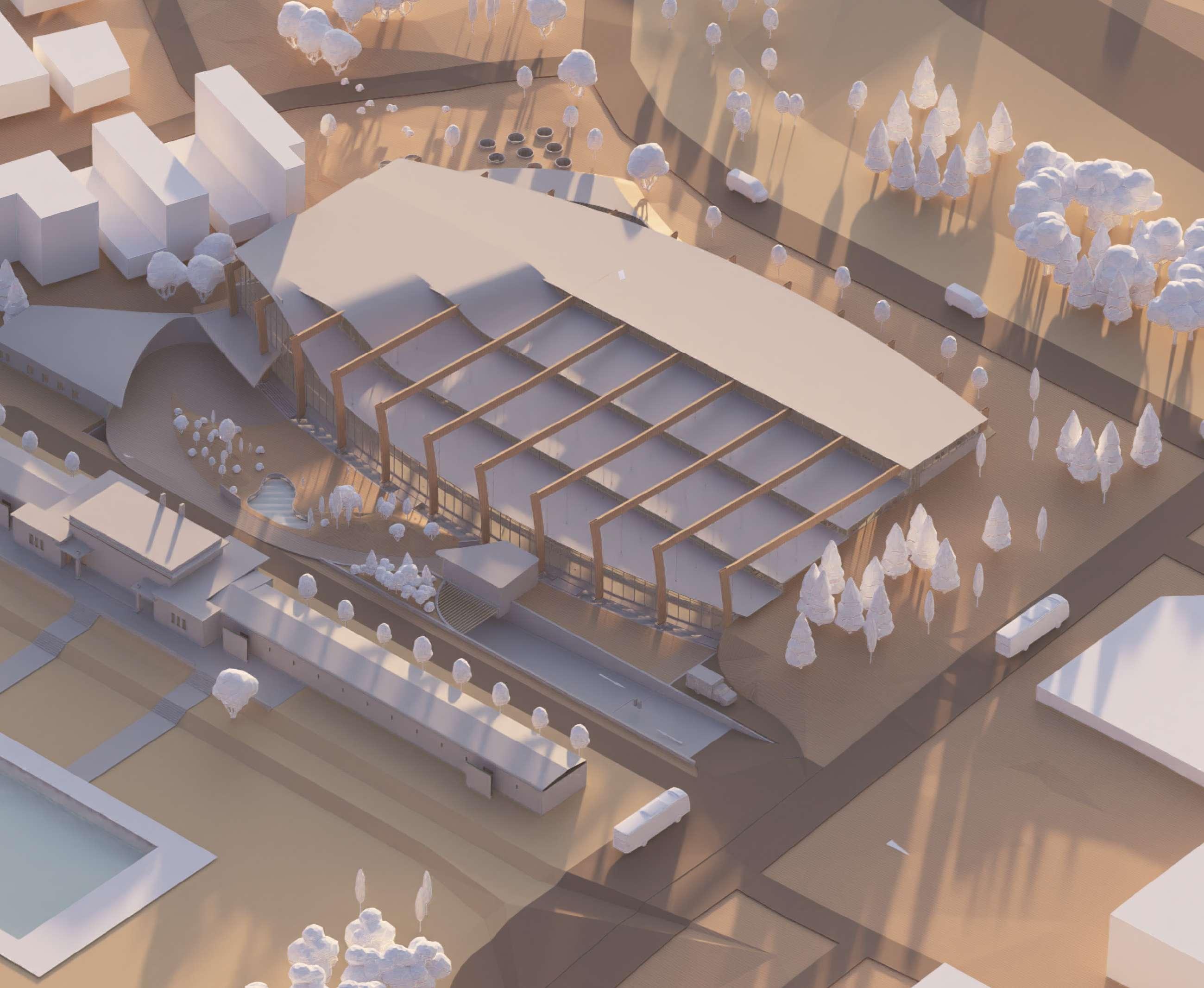
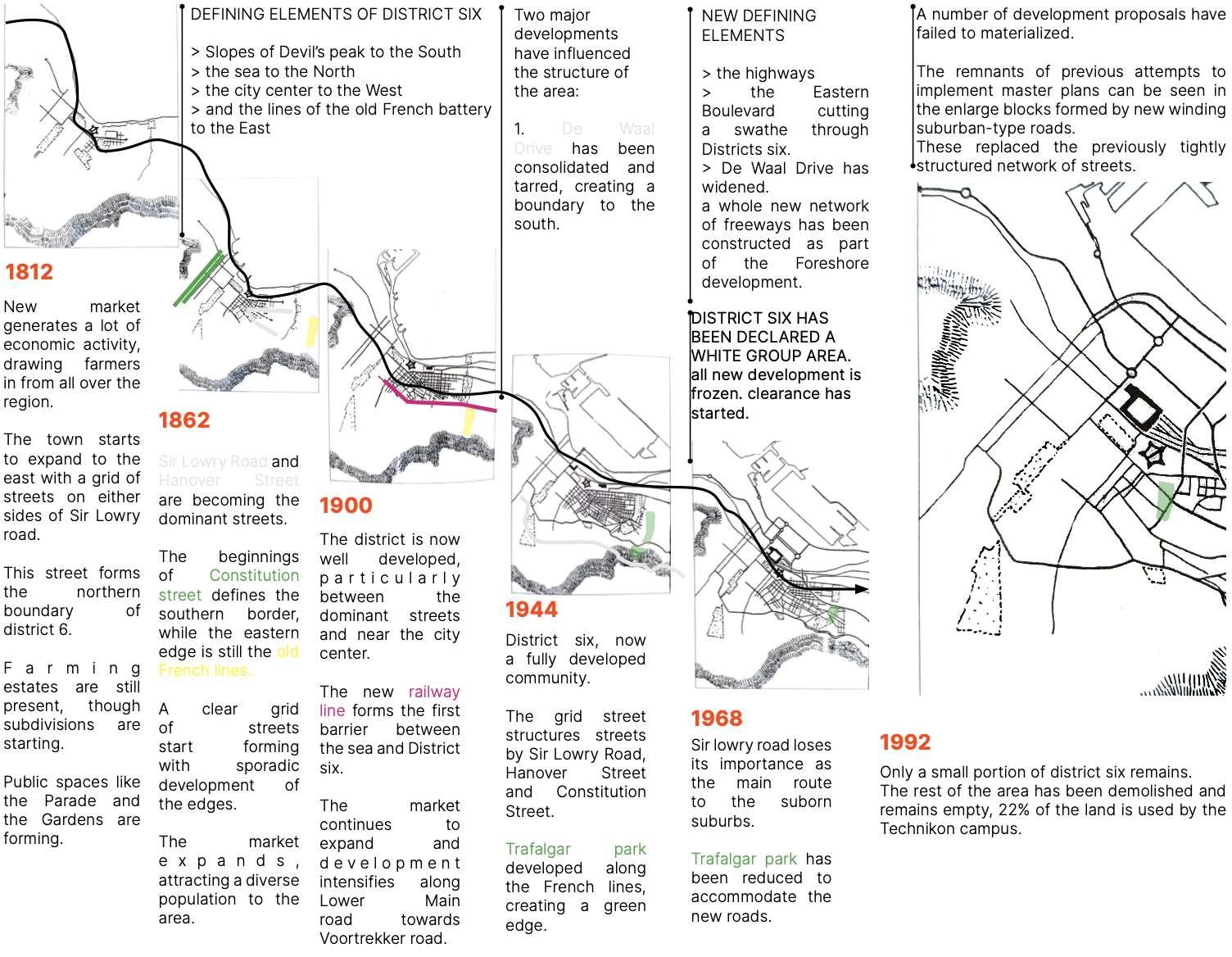
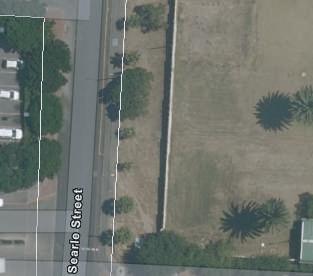
NARRATIVE
Landscapes of Connection delves into various interconnected dimensions to develop a conceptual framework for designing an aquatic community centre within a dynamic community park bordering District Six. These dimensions encompass the rich histories of District Six and Woodstock, the significance of Trafalgar Park and its Swimming Pool as historical landmarks, as well as the diverse needs, aspirations, and involvement of the local community.
Landscapes of Connection delves into the theme of water, exploring its historical significance in Cape Town, particularly within the context of the Camissa and Trafalgar River systems. It examines water’s dual role as both a connector and a divider, as well as its diverse applications in sport, healing, recreation, and economic development.
PROPOSAL DATA
TYPE
DATE
LOCATION
PROFESSOR
COLLABORATORS
Landscapes of connections
12 February - 19 March 2024
Langa, Cape town
Hermie Delport
Gideon Malherbe
3 AQUATIC CENTRE 0.1
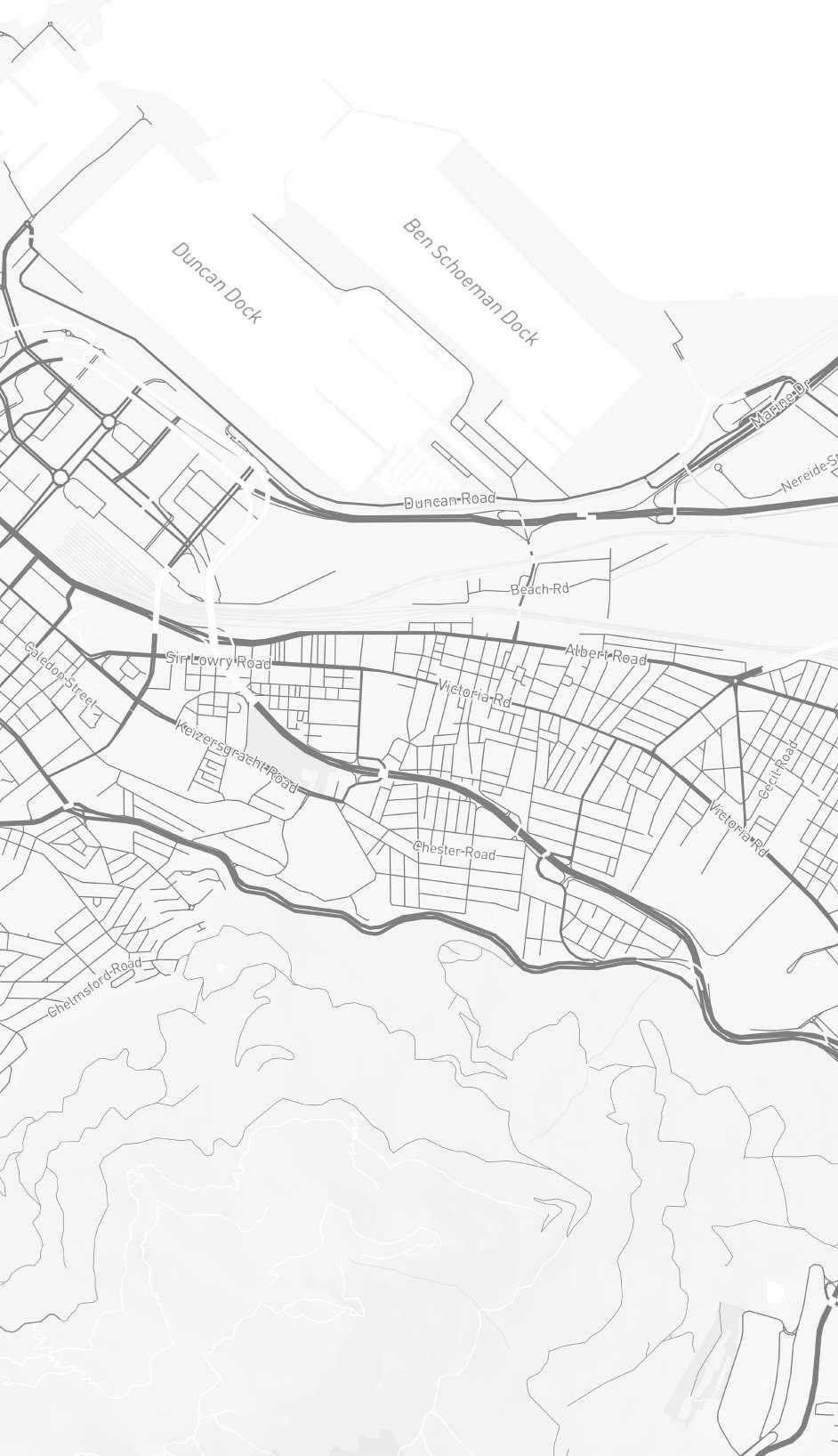
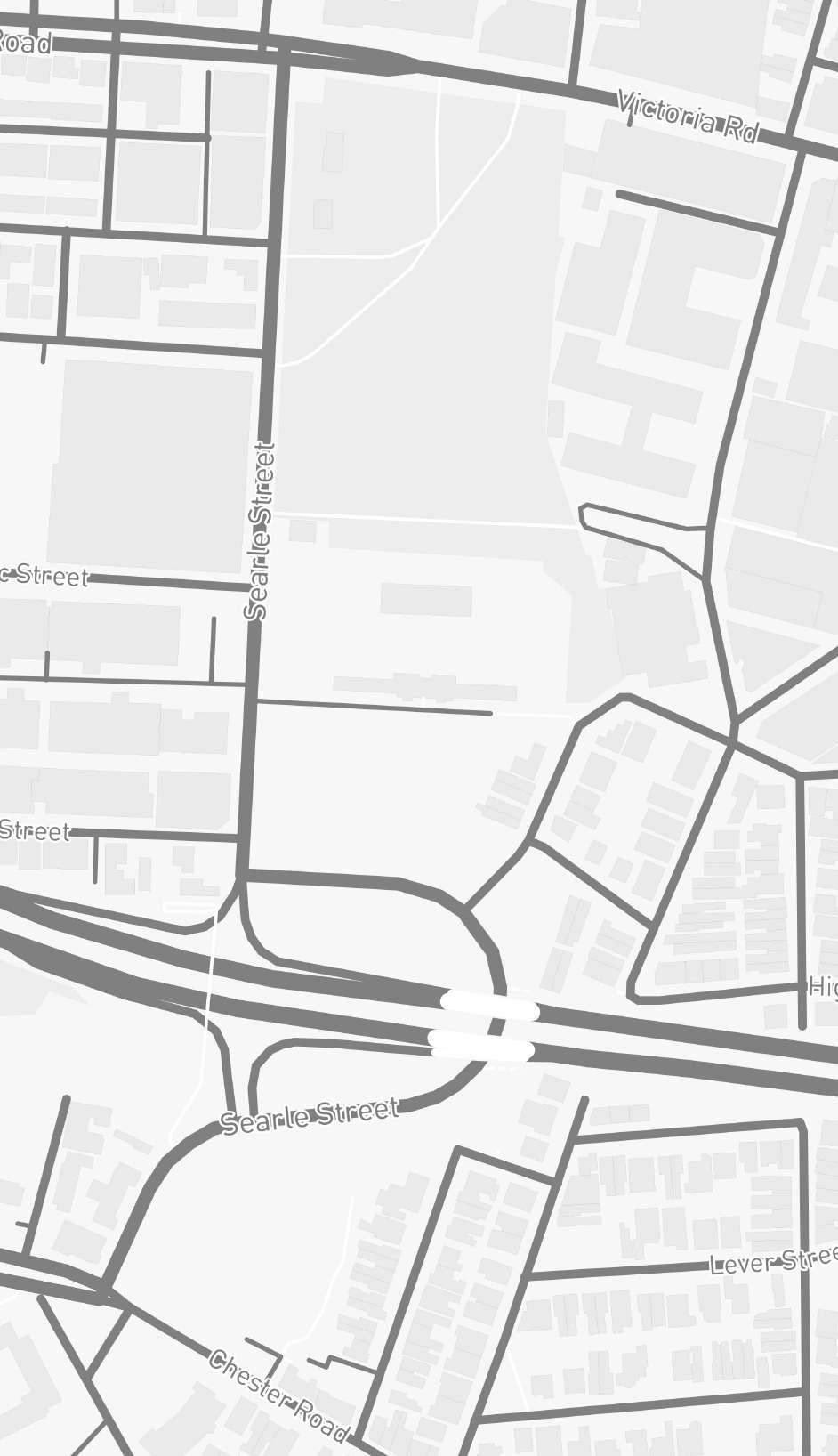
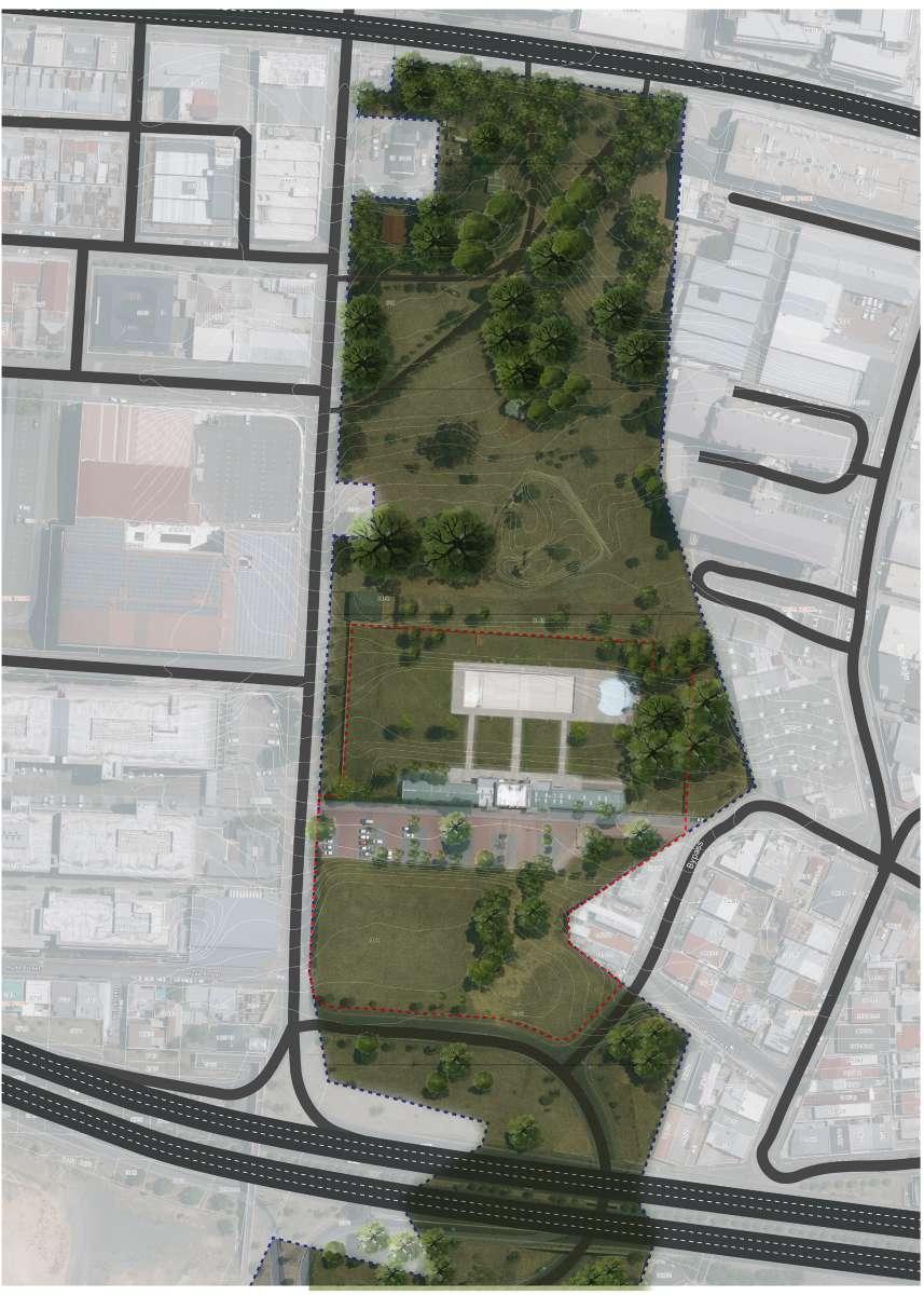
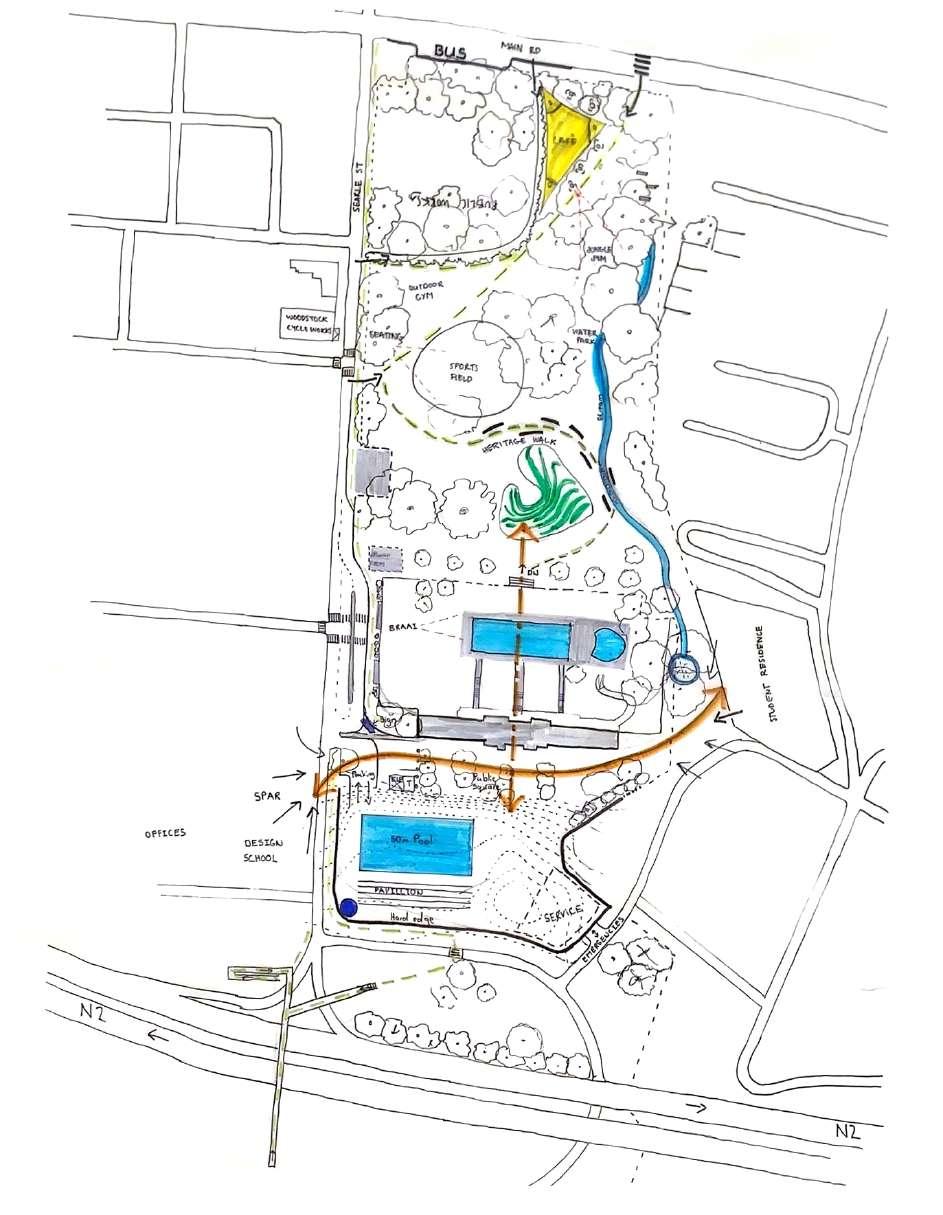

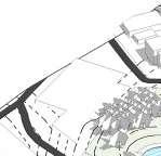
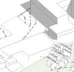

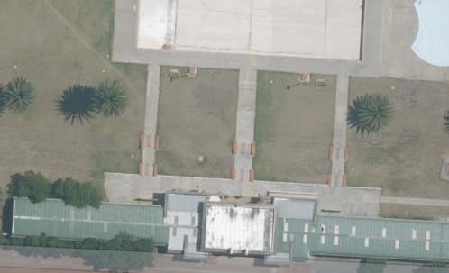
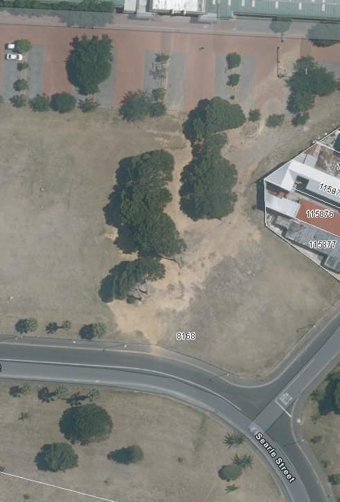
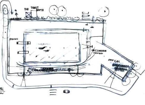
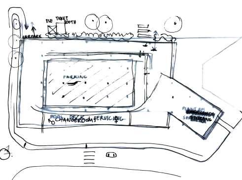
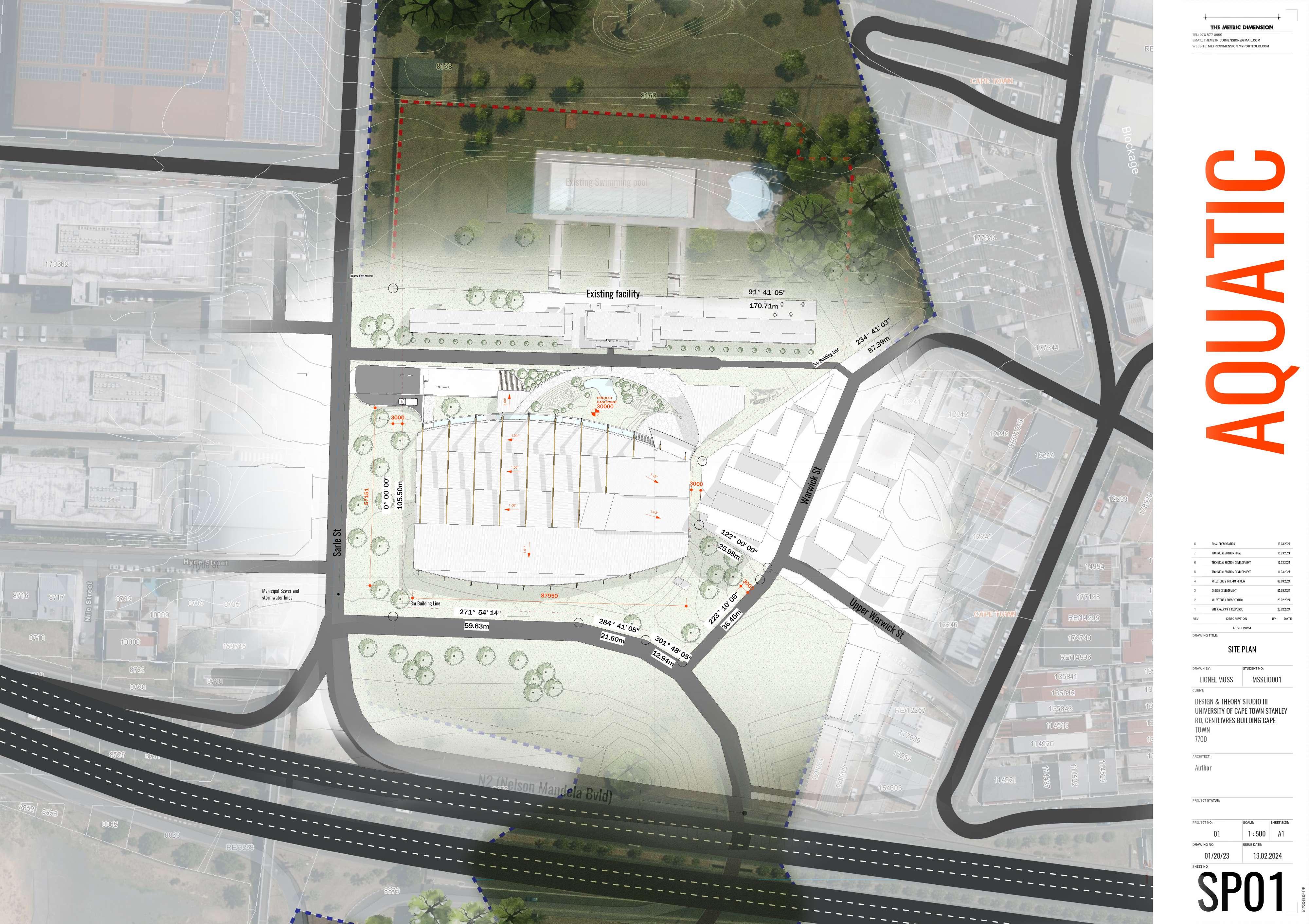
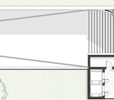
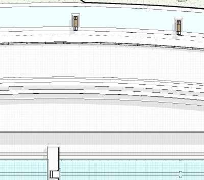
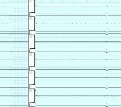
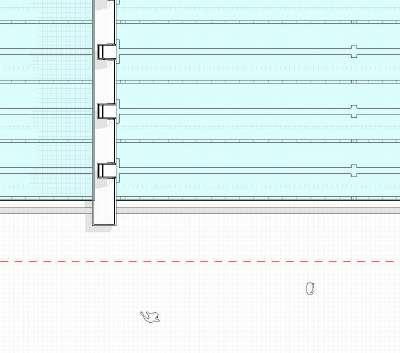
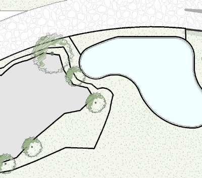
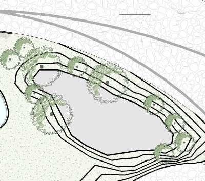
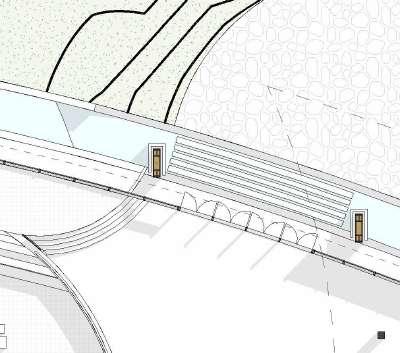
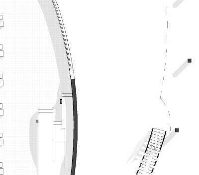
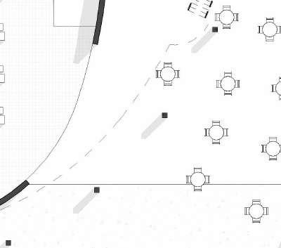
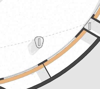
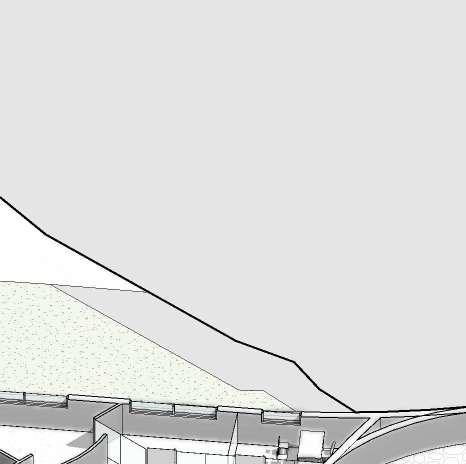
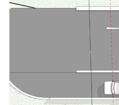
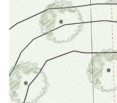
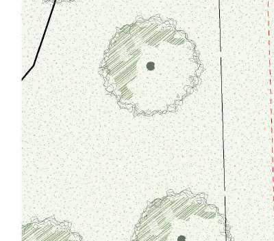
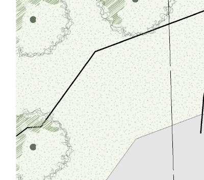
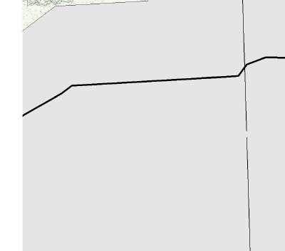
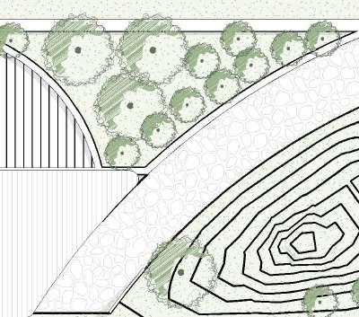
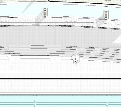
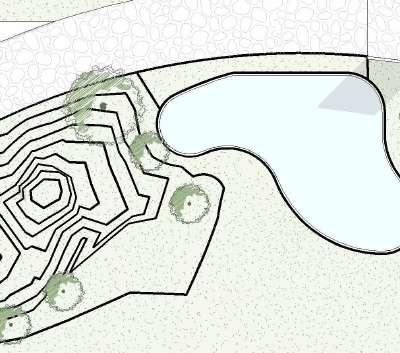
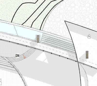
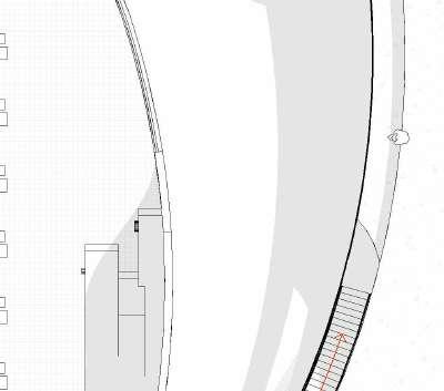
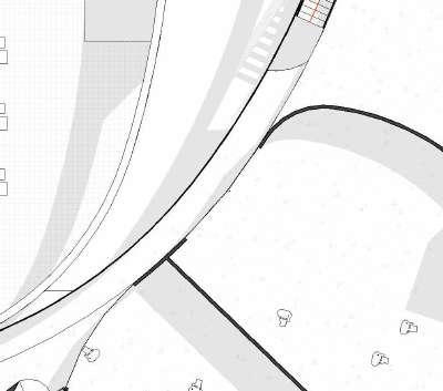
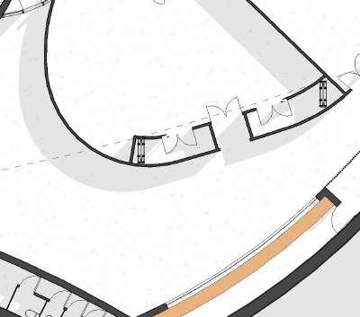
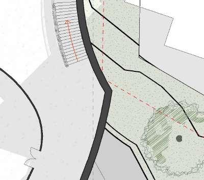
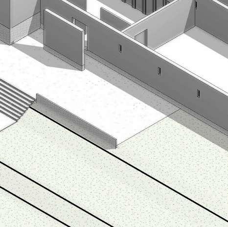
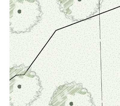
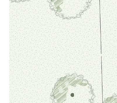
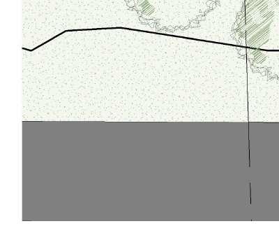
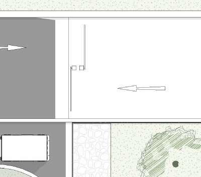
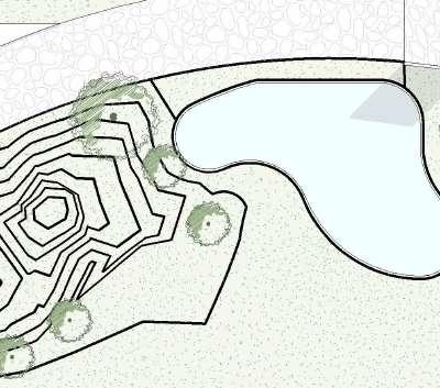
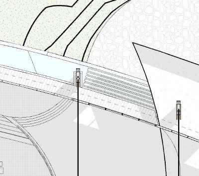
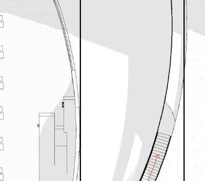
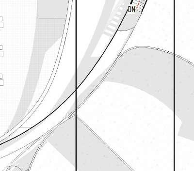
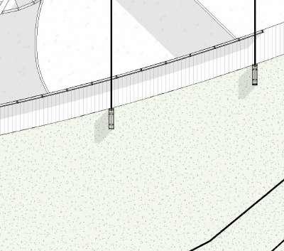
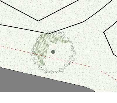
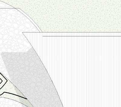
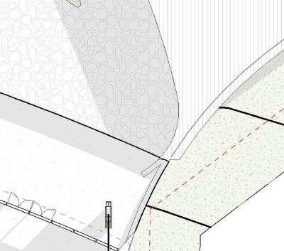
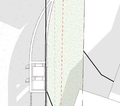
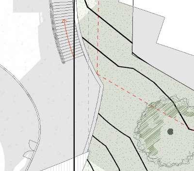
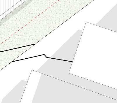
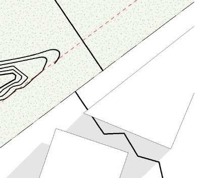
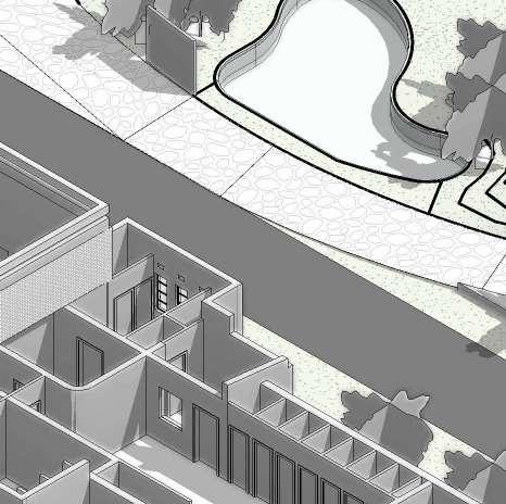
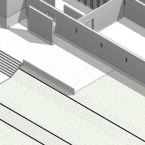
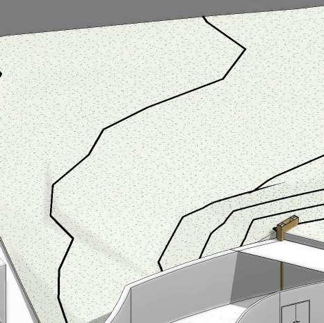
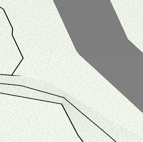
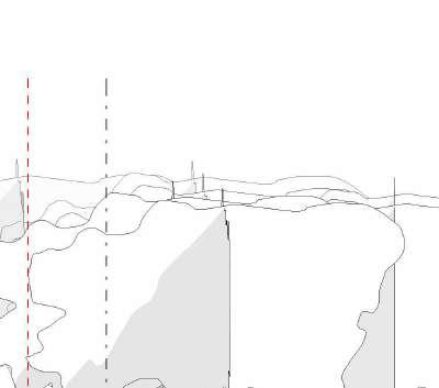
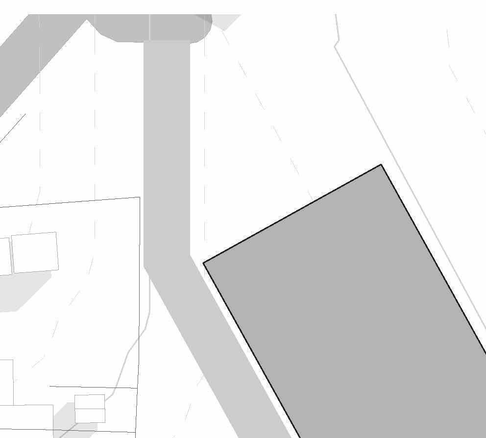
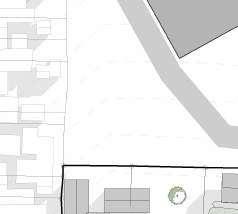
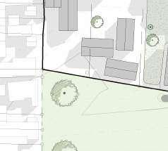
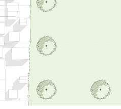
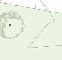
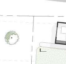
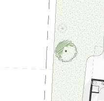
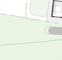
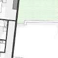
4 SITE PLANS AQUATIC CENTRE 0.1 3 SUNET 19:43 SUNRISE 06:19 NOON 12:00 N CONCEPT STATEMENT 0.1 WHAT ARE WE CONNECTING? Students and office personnel will move through the free public buffering zone from the east to west and use it as relaxation area or a lunch spot. Following the existing axis from North to South While respecting the community and its public pool, we hope to start honoring the heritage of their culture and history with a heritage walk. This will consist of the history of District Six and Trafalgar Park. 4 types of areas in one Students 2. Community from swimming pool 3. People coming from the office for a lunch break 4. Olympic sporty individuals for the aquatic center. To satisfy a variety of needs from different types of environments, we tried creating central connecting point open to the public. Buried as to not impose on the exaiating public domain. From the west to east, we designed a fluid path between the new and existing buildings. This will be inhabited by students from the developing student accommodation and the animation school, as well as people working in the office blocks. Seating area for lunch period as well as people waiting for the pool to get space for more people. 1:1000 Base Site Plan Woodstock, Cape Town Trafalgar Park, Woodstock Axo Site model 1:1000 Site intervention
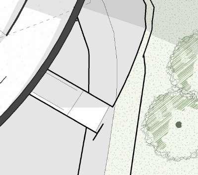
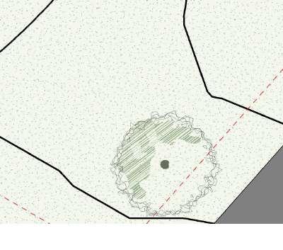
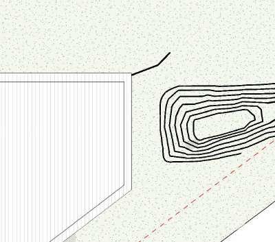
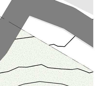
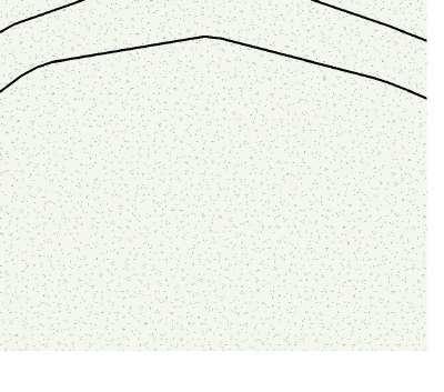
5 . HISTORY OF THE SITE 0.1
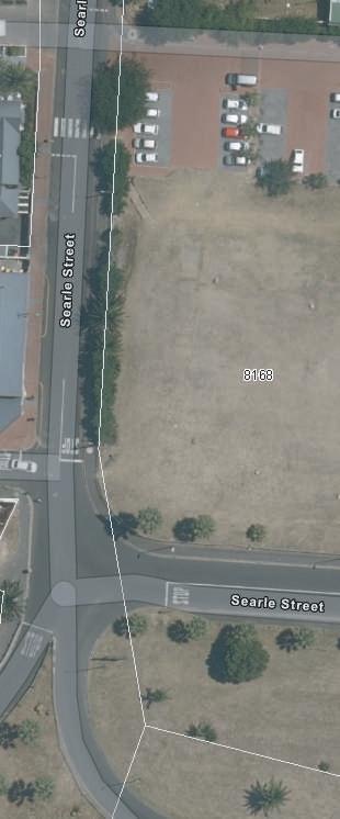
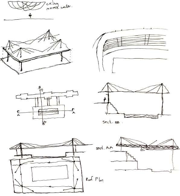
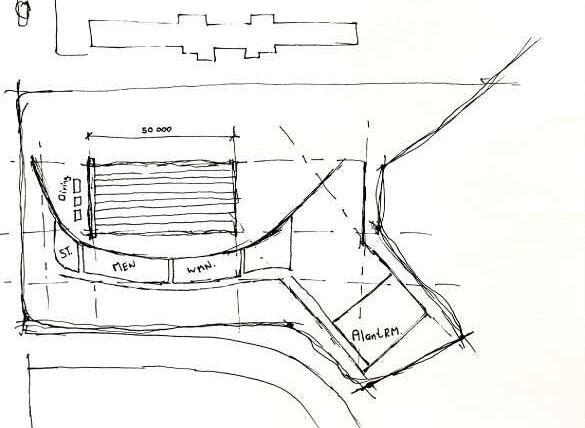
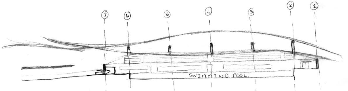
Plan Drawings Initial Concept long section
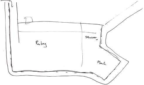
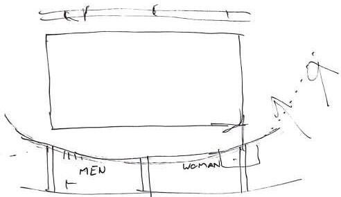
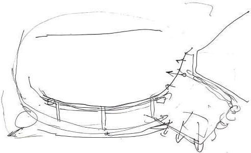
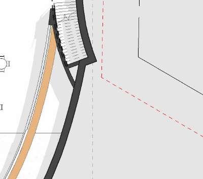
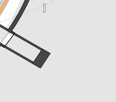
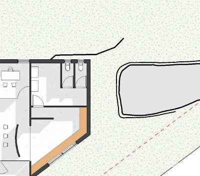
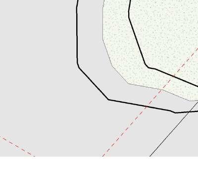
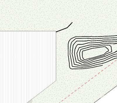
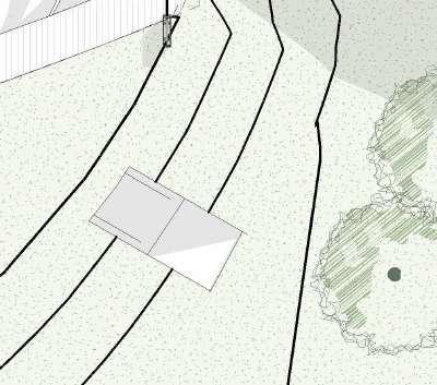
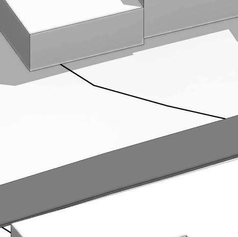
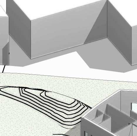
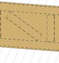
6 1:500 N Lionel Moss . CONCEPT SKETCHES 0.1 7 Quick Hand sketches of possible building footprints within the given site boundary 1:500 A3 N Lionel Moss Design Studio III APG3038W, 2024 Landscape of connections Community Aquatic Centre 0m 25m 50m Existing Building Existing Parking lot Hard Edge of proposed site 1:500 POSSIBLE BUILDING PROPOSALS 0.2 0.3
Spatial
Identifying the building footprint Identifying the building footprint in regards to site boundaries
Quick Hand sketches of possible building ootprints within the given site boundary
Initial Concept long section
Section
Rough
8 0.1


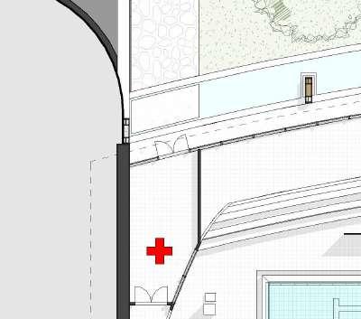
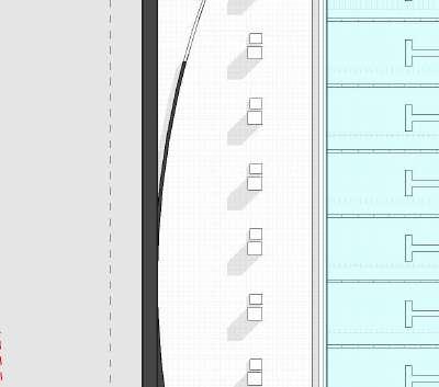
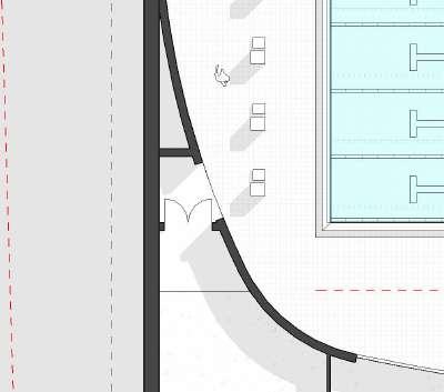
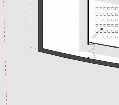
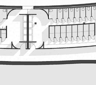
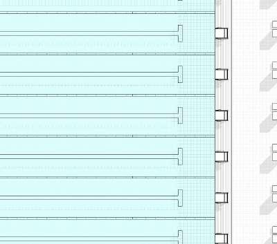
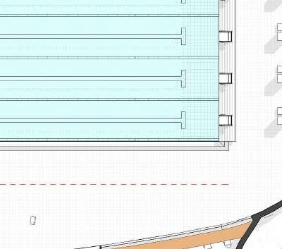
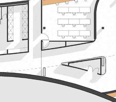


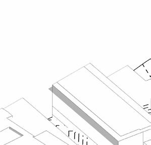
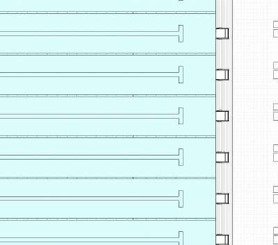
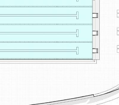
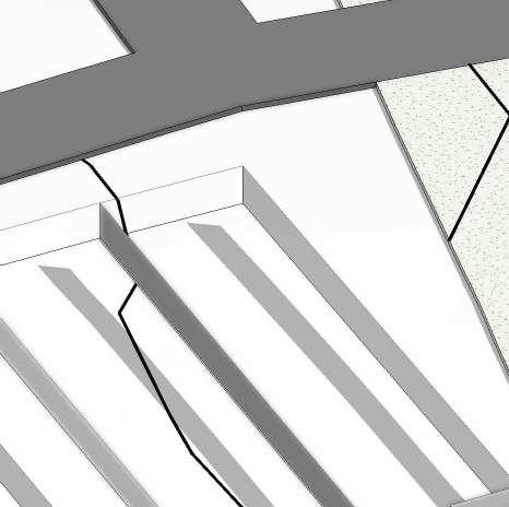
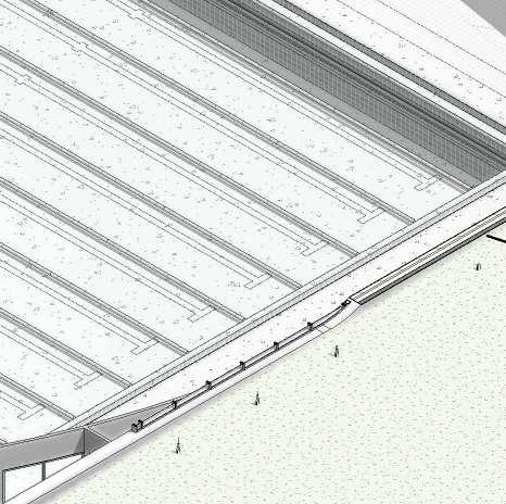
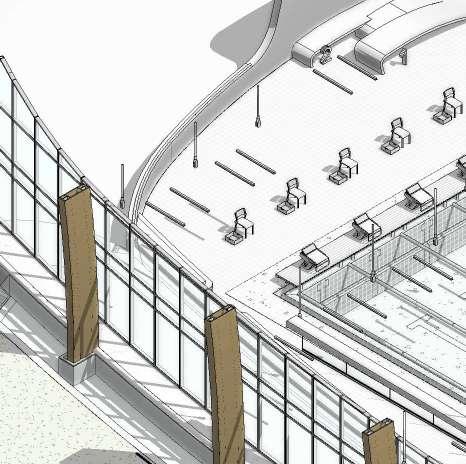
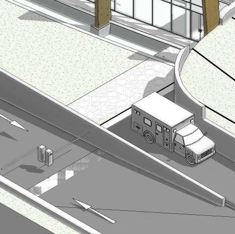
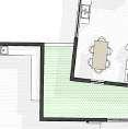
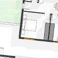
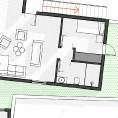
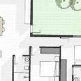
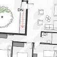
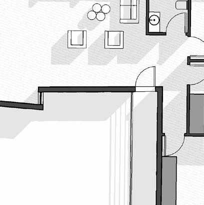
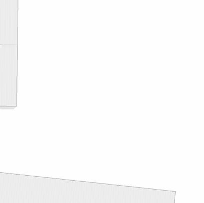
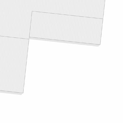
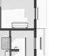
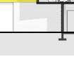
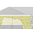
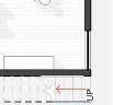
10 1:200 GROUND FLOOR PLAN 0.1 1 A301 3 A301 2 1 A201 1 2 4 6 7 A B C D E F 2 A201 9 3 5 8 10 11 A'' A' 75 m² Storage Room 57 m² Marshaling Room 106 m² Male Chaning Room 106 m² Female Changing Rooms 56 m² Technical Room 39 m² Cafeteria 26 m² Shop 2 21 m² Shop 1 62 m² Office 8 m² 1 8 m² 2 8 m² 3 8 m² 4 17 m² Bathroom 19 m² Kitchen 10 m² BoardRoom 10 m² Manager 129 m² Wallway Showers Bench Bench Dressing Cubes ST Basins Showers Bench Bench Basins Dressing Cubes Ticket Office Elevators to Basement parking Informationboard Vehicle access control Ambulance Bay during Gala events Reception Reception Waiting area ST Server room Start/Finish Line Start Line for 50m Events Starter Referee Judges of stroke Chief inspector of turns Chief inspector of turns Judges of stroke Starter Referee Athlete kit changing for 50m events only Inspector of turns Finish camera Athlete kit change Inspector of turns Medal ceremony BalconyLineoverhead Berm Berm Lake Grass Berm Information board Seating area Moveable Bulkhead Emergency Doors Emergency Doors Light Shaft 3.62° Lifegaurd Tower Ramp to Basement Parking(UP) Main Entrance 3m Building Line Pebble Pathway 3m Building Line Site Boundary Site Boundary 3mBuildingLineSiteBoundary 3mBuildingLineSiteBoundary Storage First Aid room Ramp up from pooldeck to NG Level Roofline Roofline Roofline SCALE: PROJECT NO: ISSUE DRAWING NO: PROJECT STATUS: ARCHITECT: CLIENT: DRAWN BY: STUDENT DRAWING TITLE: REVIT 2024 SHEET NO LIONEL MOSS REV DESCRIPTION AQUATIC A102 FLOOR PLANS 01 03 Author DESIGN & THEORY STUDIO UNIVERSITY OF CAPE RD, CENTLIVRES BUILDING TOWN 7700 SCALE: 1 : 200 1 00 FFL Pooldeck New SITE ANALYSIS RESPONSE MILESTONE PRESENTATION DESIGN DEVELOPMENT MILESTONE INTERIM REVIEW TECHNICAL SECTION DEVELOPMENT TECHNICAL SECTION DEVELOPMENT TECHNICAL SECTION FINAL FINAL PRESENTATION
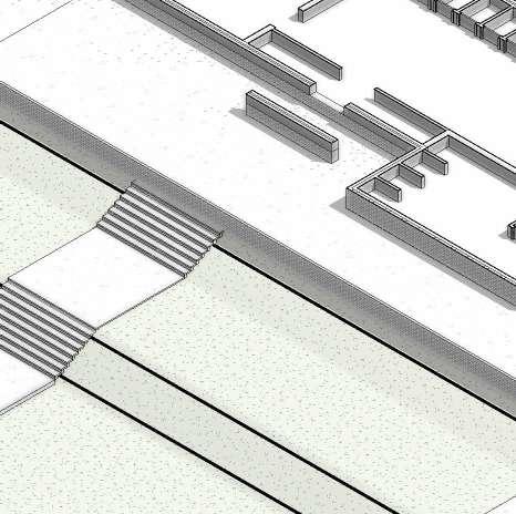
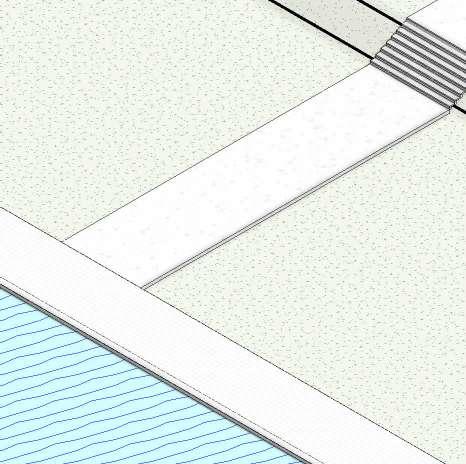

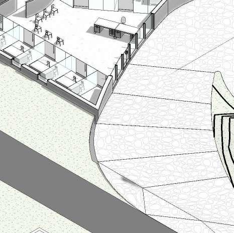


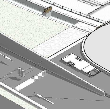

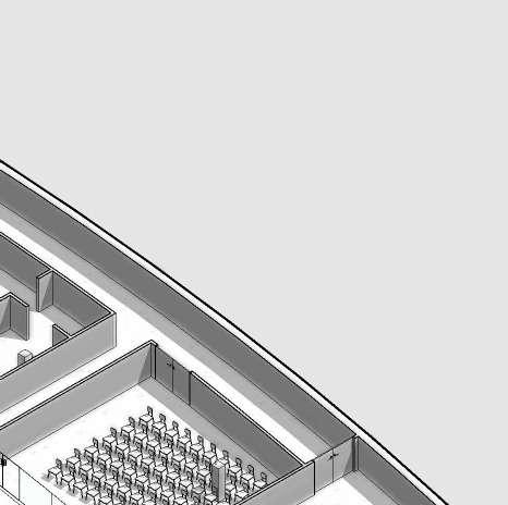
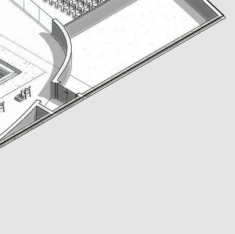

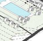
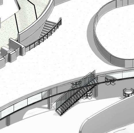
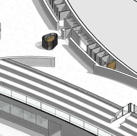
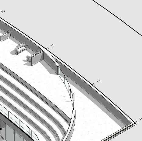
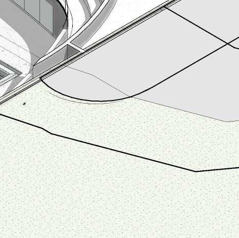
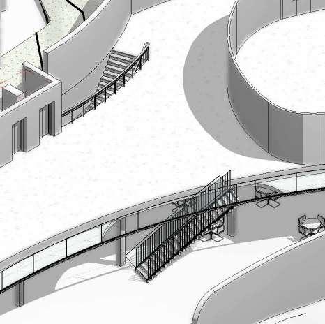
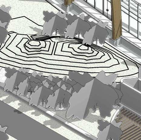
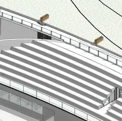
AXO GROUND FLOOR PLAN 0.1 50m Olympic standard pool Lifeguard tower & medical room Ambulance bay Bathrooms & changing facilities Technical Room Offices New landscaping Existing Building Reception Podium Marshal Room Pool storage Area


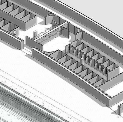
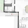
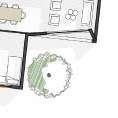
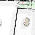
12 1:200 FIRST FLOOR PLAN 0.1 1 A301 3 A301 2 1 A201 1 2 4 6 7 A B C D E F 2 A201 9 3 5 8 1:15.79 1.68° 10 11 A'' A' 68 m² Athlete's Hospitality area 5.00° Exterior Balcony Interior Balcony Pavilion (Capacity 2000_ VIP Area 122 m² Venue 21 m² Female 17 m² Male 92 m² Marshal's Lounge Office Roof Athlete's Lounge Cafe 3m Building Line 3m Building Line Site Boundary Site Boundary SiteBoundary 3mBuildingLineSiteBoundary Gravel strip for drip Chain gutter to drain into SCALE: PROJECT NO: ISSUE DRAWING NO: PROJECT STATUS: ARCHITECT: CLIENT: DRAWN BY: STUDENT DRAWING TITLE: REVIT 2024 SHEET NO MOSS ONEL L O REV DESCRIPTION AQUATIC A103 PAVILION 01 04 Author DESIGN & THEORY STUDIO UNIVERSITY OF CAPE RD, CENTLIVRES BUILDING TOWN 7700 SCALE: 1 : 200 1 02 FFL Pavillion SITE ANALYSIS RESPONSE MILESTONE PRESENTATION DESIGN DEVELOPMENT MILESTONE INTERIM REVIEW TECHNICAL SECTION DEVELOPMENT TECHNICAL SECTION DEVELOPMENT TECHNICAL SECTION FINAL FINAL PRESENTATION


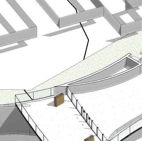
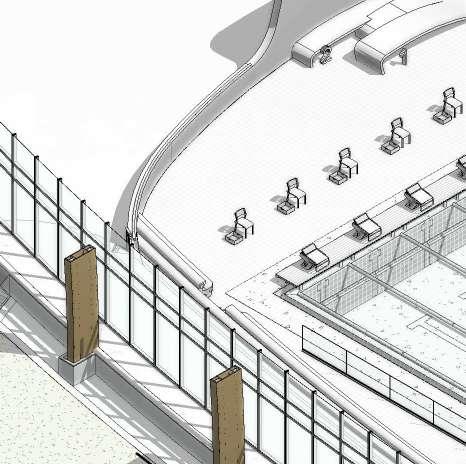


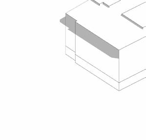
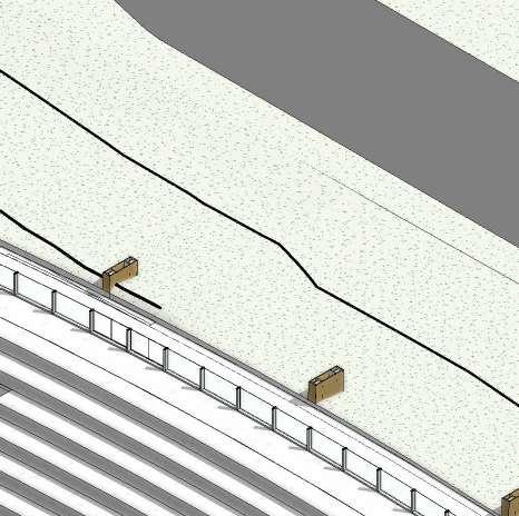
AXO FIRST FLOOR PLAN 0.1
Athlete’s hospitality area
Athlete’s lounge
Movable Bulkhead Pavilion (seats 1500 People)
Marshal’s Lounge Venue
Ticket Sales
Mezzanine viewing area & balcony Bathrooms & changing facilities

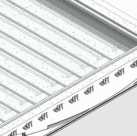
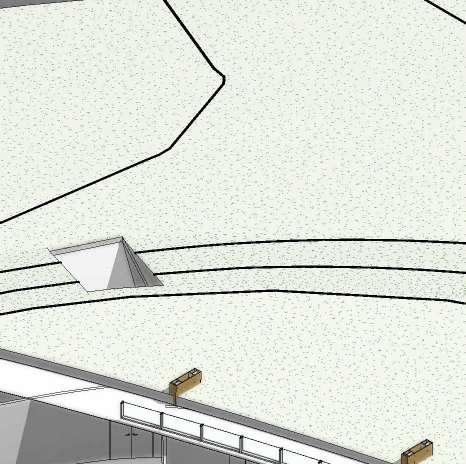
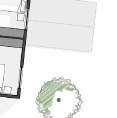
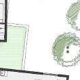
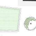
14 1:200 UPPER PAVILION FLOOR 0.1 1 2 4 6 7 A B C D E F 9 3 5 8 10 11 A'' A' Green Roof Emergency Doors Emergency Doors External Viewing area Gravel strip for drip Chain gutter to drain into SCALE: PROJECT NO: ISSUE DRAWING NO: PROJECT STATUS: ARCHITECT: CLIENT: DRAWN BY: STUDENT DRAWING TITLE: REVIT 2024 SHEET NO MOSS ONEL L O REV DESCRIPTION AQUATIC A104 TOP TIER 01 05 Author DESIGN & THEORY STUDIO UNIVERSITY OF CAPE RD, CENTLIVRES BUILDING TOWN 7700 SITE ANALYSIS RESPONSE MILESTONE PRESENTATION DESIGN DEVELOPMENT MILESTONE INTERIM REVIEW TECHNICAL SECTION DEVELOPMENT TECHNICAL SECTION DEVELOPMENT TECHNICAL SECTION FINAL FINAL PRESENTATION SCALE: 1 : 200 1 03 Top Tier


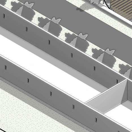

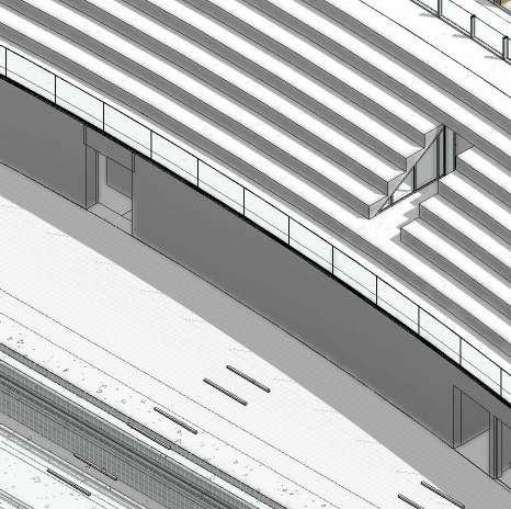
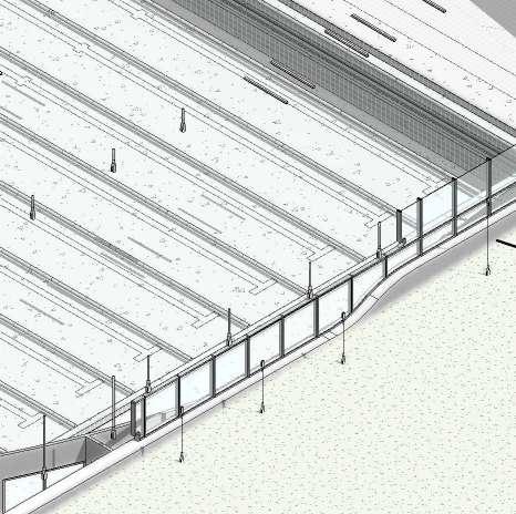


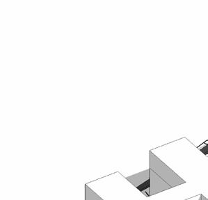
AXO UPPER PAVILION FLOOR 0.1
External Viewing platform
Green Roof


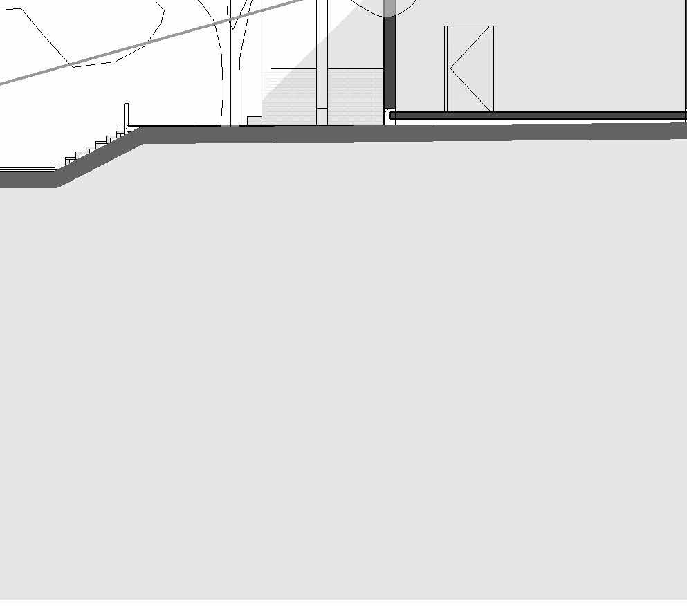
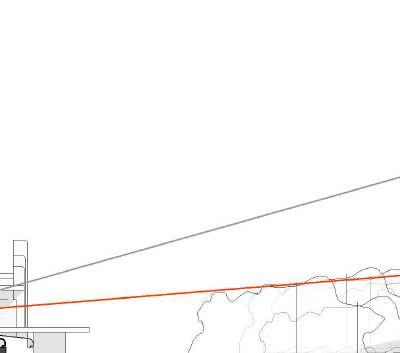
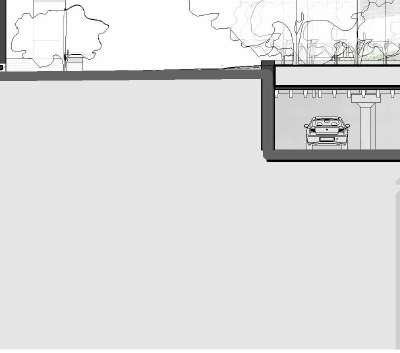
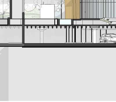

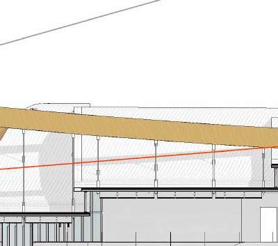
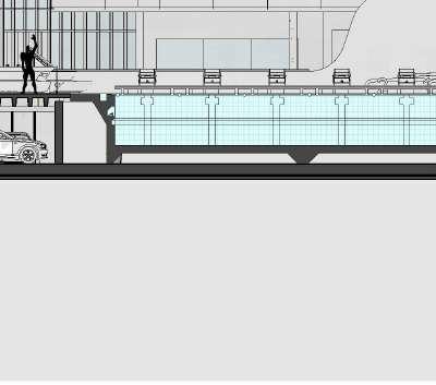

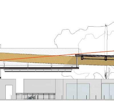
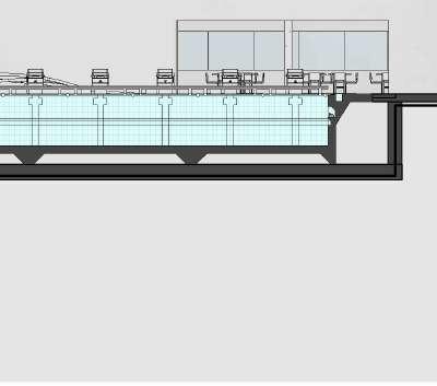
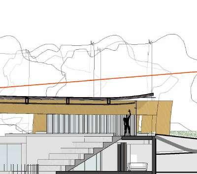

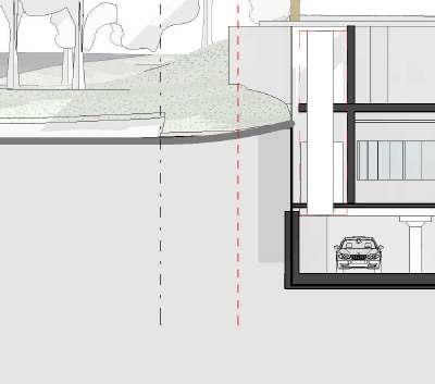

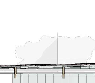
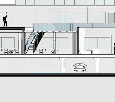
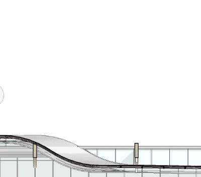
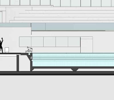
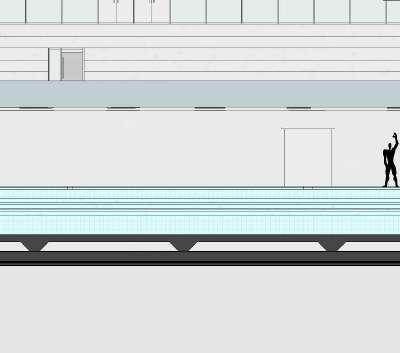
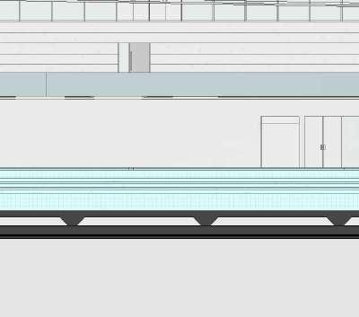
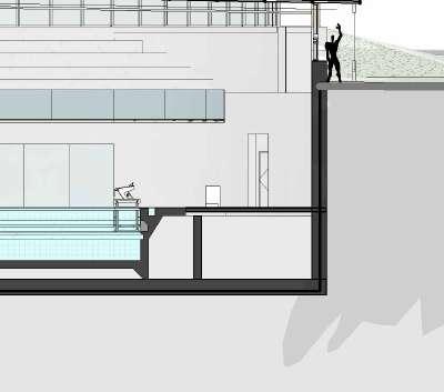


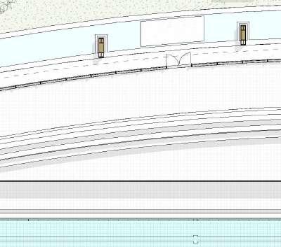
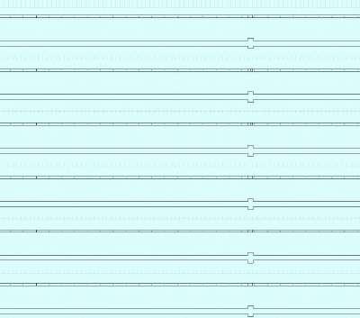
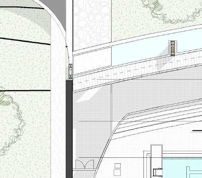
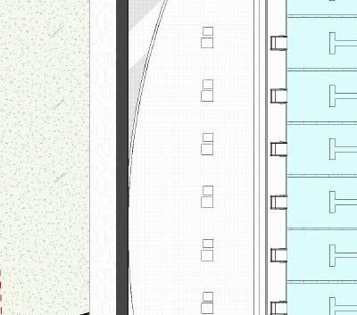
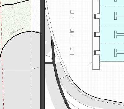
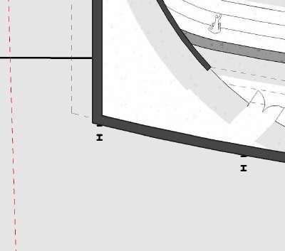
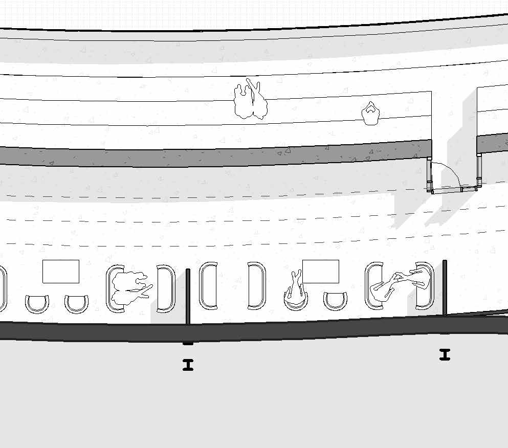
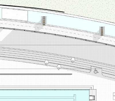
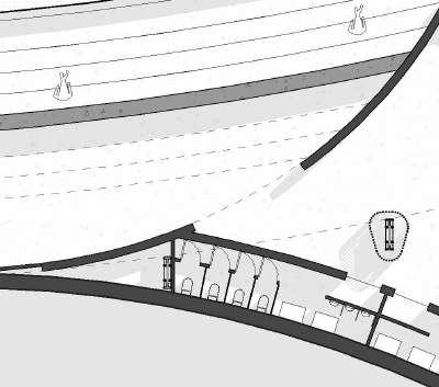
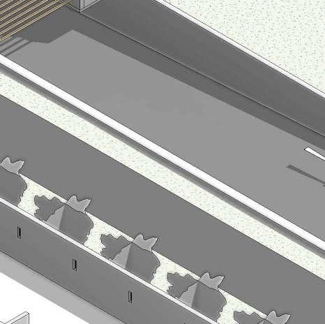
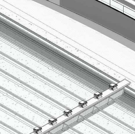
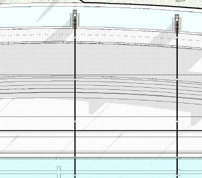
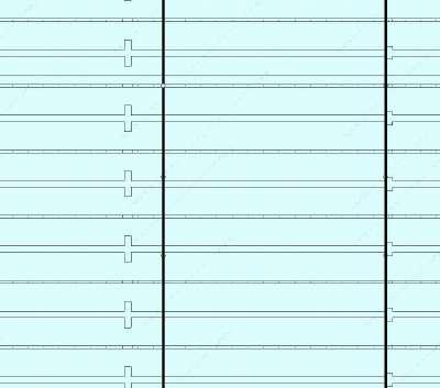
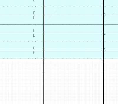
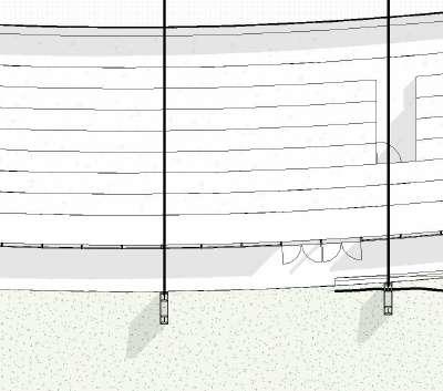
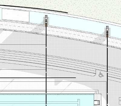
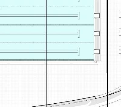
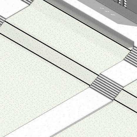
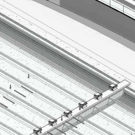
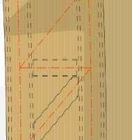
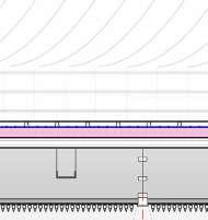
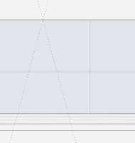
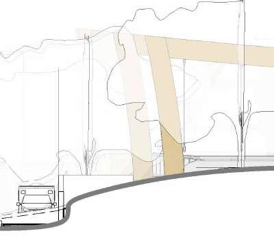
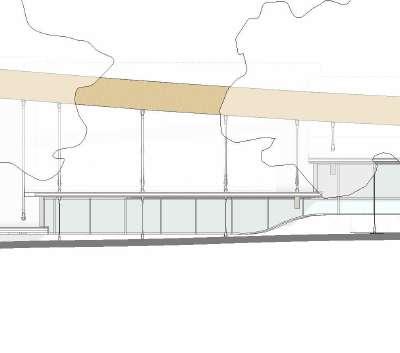
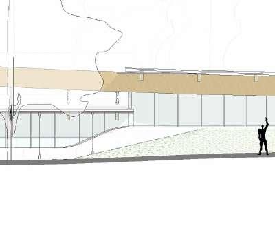
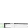
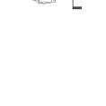
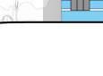
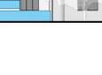
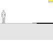
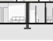
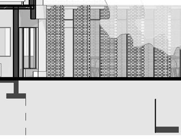
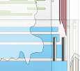
16 01 NGL LEVEL +30000 02 FFL Pavillion +33000 03 Top Tier +36000 -01 FFL Parking & Plant Room +26440 00 Pooldeck +29150 04 RoofPlate +39000 05 Roof Ridge +42000 A B C D E F 2 A201 Parking 50x25m Olympic Pool A'' A' Site Boundary 3m Building Line Pavilion Male Chaning Room 106m Hallway 128m 2 A202 1 3500 3500 3000 3500 3500 3000 3500 3500 3000 3d Model +35440 01 NGL LEVEL +30000 02 FFL Pavillion +33000 1 A201 03 Top Tier +36000 -01 FFL Parking & Plant Room +26440 00 Pooldeck +29150 04 RoofPlate +39000 05 Roof Ridge +42000 1 2 4 6 7 9 3 5 8 10 11 Plant Room Parking Pavilion (Capacity of 2000) Technical Room Female Chaning Room Male Changing Room Marshaling Room Moveable Bulkhead Storage Podium Site Boundary 3m Building Line Sarle St Site Boundary 3m Building Line 1.00° 3d Model +35440 SCALE: PROJECT NO: ISSUE DRAWING NO: PROJECT STATUS: ARCHITECT: CLIENT: DRAWN BY: STUDENT DRAWING TITLE: REVIT 2024 SHEET NO MOSS ONEL L O REV DESCRIPTION AQUATIC A201 SECTIONS 01 06 Author DESIGN & THEORY STUDIO UNIVERSITY OF CAPE RD, CENTLIVRES BUILDING TOWN 7700 SCALE: 1 : 200 1 Section 1 2 Section 2 SITE ANALYSIS RESPONSE MILESTONE PRESENTATION DESIGN DEVELOPMENT MILESTONE INTERIM REVIEW TECHNICAL SECTION DEVELOPMENT TECHNICAL SECTION DEVELOPMENT TECHNICAL SECTION FINAL FINAL PRESENTATION 1:200 SECTIONS 0.1


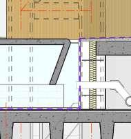
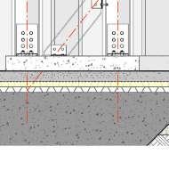

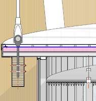
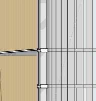
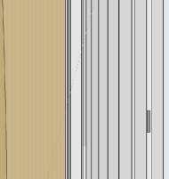
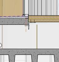
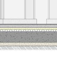
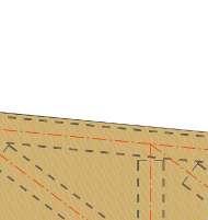
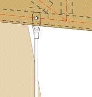

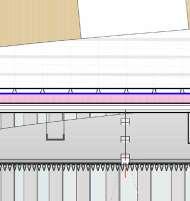
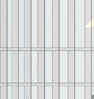

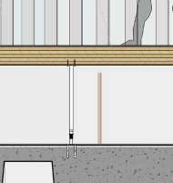
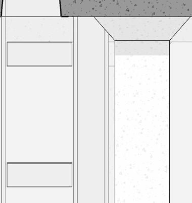
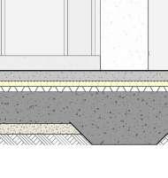
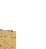
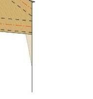

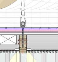
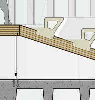
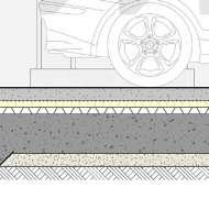
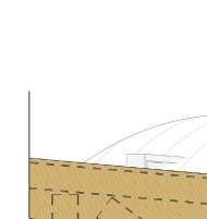
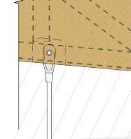


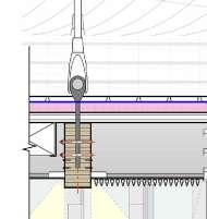
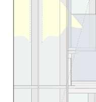
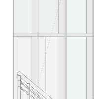
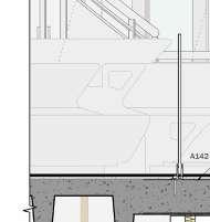
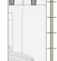
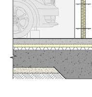
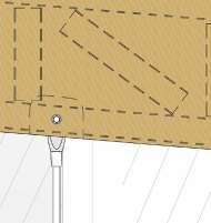
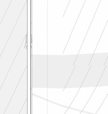

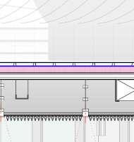
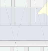

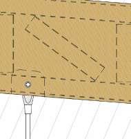
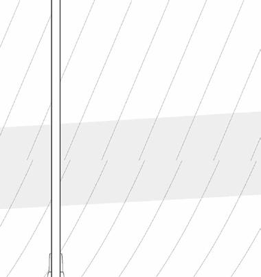
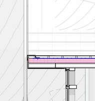
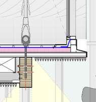
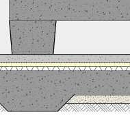


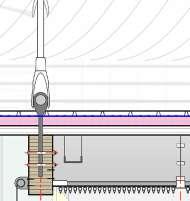
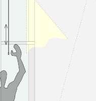


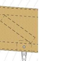
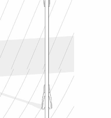

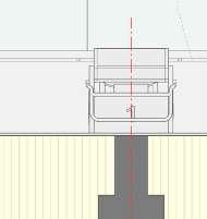
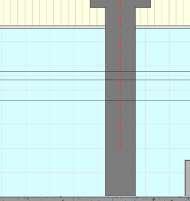
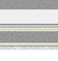
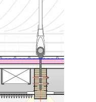

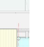
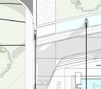
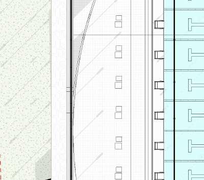
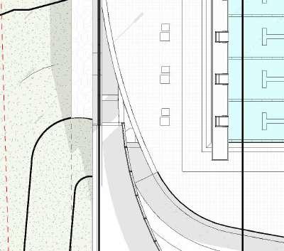
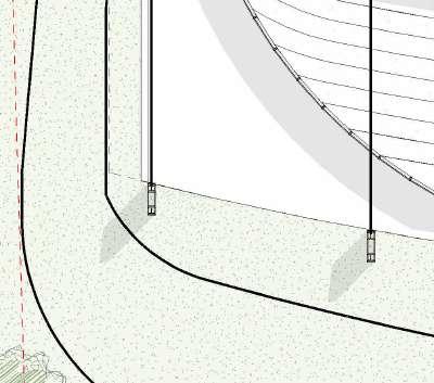
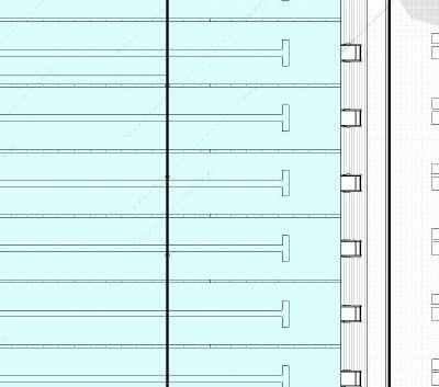
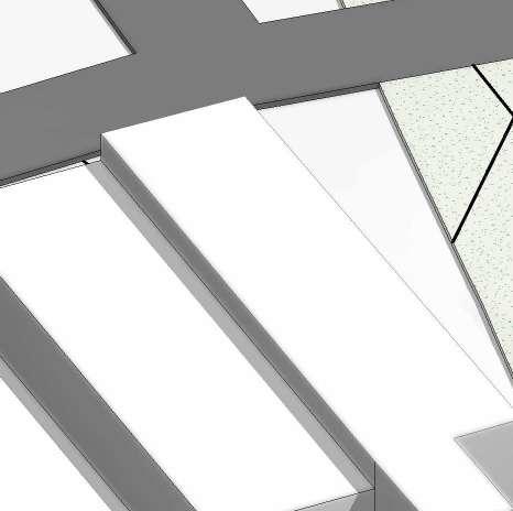
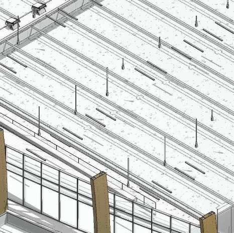
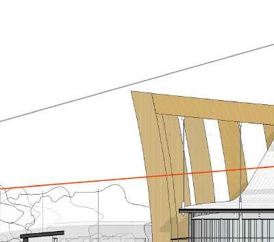
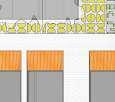
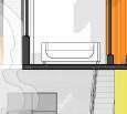
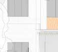
17 01 NGL LEVEL +30000 02 FFL Pavillion +33000 03 Top Tier +36000 -01 FFL Parking & Plant Room +26440 00 Pooldeck +29150 04 RoofPlate +39000 05 Roof Ridge +42000 A B 850 2710 250 500 300 CL CL 2500 2400 2500 610 115 495 Height complies with SANS Height restrictions for below grade parking garages 2230 (Min 2000 as per FR XX) 100mm Concrete Screed Separation Layer 50mm Compression + moisture resistant thermal insulation 50mm Drain layer to enable water flowing below floor to drain channel 300mm Concrete slab Laneropes C.O. Lane 2000 300 410 300 1700 HVAC FFL Pooldeck New 500 3500 3500 3000 1000 500 3500 11500 Rest Ledge as per FR2.4.2 130 240 Gutters as Per FR 2.4.3 250 FR 2.5 Lanes shall be at least 2.5 meters wide, with two spaces of at least 0.2 meter outside of the first and last lanes. 120 Larerope diameter complies with FR 2.6.1 Staring blocks complies with FR2.7 & FR2.8 Light intensity over starting platforms and turning ends shall not be less than 600 lux to comply with FR2.13 Lane markings comply with FR2.14 Touch Pad complies with FR4.4 Automatic lap Counters as per FR4.6.5 2400 600 300 640 500x200mm Glulam Beam suspended from 60mm High tensile steel rods with custom made M/S brackets 3500mm C.T.C. 100mm Sand substrate All windows and door opening as per the Window Schedule. All glass in accordance with Part N the SANS-10400. 60mm Stainless Steel Structural-Ronstan-Rod SystemACS1 fixed to Steel Pratt Truss with mechanically fastenings 3500mm C.T.C. as per structural engineer's detail Foundations according to SANS 2001-CM2, according to engineer specifications. As well as in accordance with SANS 10400-H for foundations. G5 Engineered Compacted ground 254X254X167 Macsteel UC H-Columns to form N-Braced girder column with 203x133x25 UB I-Section crossbracing. Mechanically fixed to concrete foundation with 20mm M/S Baseplate M12 anchor hooks 450 450x450mm RC column with drop caps according to structural engineer's specifications 300 1700 300 70mm Thick x2000 Concrete shell Step across the water Single skin supporting brick wall 31mm Pedestal to support the raised floor, spaces 1200mm C.T.C. and 200mm either side of threshhold as indicated A401 300mm NFX Facebrick cavity wall with brickforce every 5th course horizontally 300 LAP 1140 1100mm Glass balustrade according to SANS 10104: Part M according to specialist's design Chromadek Klip Lop-700 profile, Steenberg Charcoal Grey sheet 1° roof pitch on enviroutough reflective foil 400mm provision for services between U.O. roof and T.O. Ceiling Glass in balustrades shall be toughened safety glass According SANS 10137 1200x300mm Pratt Truss 203x133x25 members according to structural engineer's specifications. 30mm timber cladding attached to steel truss WaterLevel OSB11 OSB11 Moveable bulkhead rail as per FINA regulations 900 XLAM XT5x165 Floor according to manufacturer's specifications 76x50x20x2.0mm Lipped channel purlin fixed to glulam beam 1800mm C.T.C. HVAC HVAC HVAC A401 2 NGL One layer of bitumen waterproofing membrane, with 75mm side laps and 100mm end laps sealed to primed surface to falls as cross falls by 'torchfusion', including protection of 150mm thick layer clean topsoil on thick drainage core and horizontally on waterproofing covered with geomesh PVC coated multifilament woven polyester biaxial reinforcing mesh and bide, A2 non-woven continuous filament needle-punched polyester geotextile under topsoil. Install above screed to fall as per detail LED accent strip lighting 200 2010 B2 B1 A1 A2 A3 A4 5.00° Pratt Truss fixed to N-Braced frame with at three locations according engineer's specifications with M/S plates an M12 bolted connections 2mm Aluminum Flashing overlapping with klip-Lop roof sheeting and fixed with self tapping and sealing screws as specified by manufacturer Motorized roller blind mechanism according to specialist's specifications fixed onto 200x200x16mm M/S angle plate fixed to Glulam beam with M20 Bolts as specified by engineer 2mm Aluminum Flashing overlapping with klip-Lop roof sheeting and fixed with self tapping and sealing screws as specified by manufacturer Roof overhang complies with SANS XA regulations. (0.53xHight of the window) 150x50mm Cable Tray suspended from Lip Channel prulins Counter 1220 10mm Wall tiles as per FINA regulations Provision for Mechanical Services 150x50mm Cable Tray for Data and blinds 150x50mm Cable Tray suspended from Lip Channel prulins 150x50mm Cable Tray suspended from Lip Channel prulins INNOWOOD's Slatted Aluminum extrusion Ceiling System fixed to aluminum rails 41mm C.T.C. as specified by manufacturer. LED accent strip lighting 100 150 Expanded polystyrene (eps) insulation board 100mm thick with density 16kg/m 80mm Drainage pipe 1:60 fall VOID 8mm Granite tile for external walkway Provision for Mechanical Services VOID SERVICE SPACE PARKING 8mm Granite tile for internal 8mm Granite tile for internal space Column cap Timber seating 38x38mm Vertical pine battens cladding fixed to lipped channels fixed to N_braced column G01 G02 G03 SCALE: SHEET SIZE: PROJECT NO: ISSUE DATE: DRAWING NO: PROJECT STATUS: ARCHITECT: CLIENT: DRAWN BY: STUDENT NO: DRAWING TITLE: REVIT 2024 SHEET NO O00 MSS S MO E O L DATE A0 REV DESCRIPTION BY AQUATIC CENTRE TEL: 076 877 0999 EMAIL: THEMETRICDIMENSION@GMAIL.COM WEBSITE: THEMETRICDIMENSION.COM 1 20 A202 1_20 SECTION 01 13.02.2024 07 Author DESIGN & THEORY STUDIO III UNIVERSITY OF CAPE TOWN STANLEY RD, CENTLIVRES BUILDING CAPE TOWN 7700 SITE ANALYSIS RESPONSE 20.02.2024 MILESTONE PRESENTATION 23.02.2024 DESIGN DEVELOPMENT 05.03.2024 MILESTONE INTERIM REVIEW 08.03.2024 TECHNICAL SECTION DEVELOPMENT 11.03.2024 TECHNICAL SECTION DEVELOPMENT 12.03.2024 TECHNICAL SECTION FINAL 15.03.2024 GENERAL NOTES: Do not scale drawings. Only figured dimensions to be used and overall dimensions to take preference All dimensions are in millimeters unless stated otherwise. Contractor must verify all dimensions and levels onsite before starting work. D: This drawing must be considered alongside all other relevant drawings and specifications. E: All materials and workmanship must adhere to the National Building Regulations SANS 10400 and relevant SANS codes. Contractor must obtain written confirmation from the architect for any instructions that modify the contract before proceeding. G: No variation instruction can exempt the contractor and/or subcontractors from complying with the National Building Regulations SANS 10400. H: Consult the architect for clarification on any unclear ambiguous aspects of this drawing and promptly report errors, discrepancies, or omissions. The architects retain the copyright of this drawing. CONSTRUCTION NOTES: FOUNDATIONS: (to structural engineer's specifications) 1.1 All foundations to comply with SANS 10400-H 1.2: New slab thickening to Eng. Spec where the two new timber walls are to be built. R O 2.1 All floors to comply with SANS 10400-J and SANS 10082 R M 3.1. Timber framed structures built in accordance with SANS 10082. 3.2. Timber roof trusses manufactured in accordance with Part Roofs of SANS 10400 'The Application of the National Building Regulations'. L W 4.1 All walls to comply with SANS 10400-K. 4.2 exterior walls using timber posts cladding. 4.3 DPC's to all external door and window openings. 375 micron embossed DPC. 4.4 Timber lintels over all windows and doors exceeding 3000mm. Minimum two layers (100mm) 5.WINDOWS AND DOORS 5.1 Glazing complies with SANS 10400 & N. 5.2 Glass doors that have more than 1sqm or less than 500mm above FFL to have laminated 6mm clear safety glass. 5.3 Aluminum windows and doors made to size. FINAL PRESENTATION 19.03.2024 1:20 TECHNICAL SECTION & DETAILS 0.1 03 Top Tier +36000 B 200 500 500x200mm Glulam beam suspended from 60mm high tensile steel cables according to structural engineer's specifications 76x50x20x2.0mm Lipped channel purlin fixed to glulam beam @ 1800mm C.T.C. Chromadek Klip Lop profile, Steenberg Charcoal Grey sheet 1° roof pitch on enviroutough reflective foil mechanically fixed to purlins 200x40x40x1.2 Batten hanger Fixed to Glulam beam with nails HVAC duct 60mm Stainless Steel StructuralRonstan-Rod System-ACS1 fixed to timber roof beams with mechanically fastenings @ 3500mm C.T.C. 250 450 Motorized roller blind mechanism according to specialist's specifications fixed to Glulam beam with mechanical fixing as specified by manufacturer B1 A4 1500 2mm Aluminum Flashing overlapping with klip-Lop roof sheeting and fixed with self tapping and sealing screws as specified by manufacturer Light intensity over starting platforms and turning ends shall not be less than 600 lux to comply with FR2.13 Structural silicone around Custom M/S bracket to prevent water from penetrating the Klip-Lok roof Structural silicone around Custom M/S bracket to prevent water from penetrating the Klip-Lok roof 2mm Aluminum Flashing overlapping with klip-Lop roof sheeting and fixed with self tapping and sealing screws as specified by manufacturer INNOWOOD's Slatted Aluminium extrusion Ceiling System fixed to aluminum rails @ 41mm C.T.C. as specified by manufacturer. 80 76 41 67 30 390 1000 1000 500 1167 Roof overhang complies with SANS XA regulations. (0.53xHight of the window) 150x100mm Cable Tray suspended from Lipped channel for data and motoriserd roller blinds 41 Nutec facia board 86x86x2.5mm Aluminium spacer block fixed to 125x90x2.5mm C-Section 150x50mm Aluminum Window frame fixed to spacer block as per manufacture's specifications 350 G03 Accent lighting Accent lighting Accent lighting NGL SCALE: 1 10 1 Roof Step Detail SCALE: 1 200 3 Roof Structural diagram 2 03 Top Tier +36000 B 200 500 500x200mm Glulam beam suspended from 60mm high tensile steel cables according to structural engineer's specifications 76x50x20x2.0mm Lipped channel purlin fixed to glulam beam @ 1800mm C.T.C. Chromadek Klip Lop profile, Steenberg Charcoal Grey sheet 1° roof pitch on enviroutough reflective foil mechanically fixed to purlins 200x40x40x1.2 Batten hanger Fixed to Glulam beam with nails HVAC duct 60mm Stainless Steel StructuralRonstan-Rod System-ACS1 fixed to timber roof beams with mechanically fastenings @ 3500mm C.T.C. 250 450 Motorized roller blind mechanism according to specialist's specifications fixed to Glulam beam with mechanical fixing as specified by manufacturer B1 A4 1500 2mm Aluminum Flashing overlapping with klip-Lop roof sheeting and fixed with self tapping and sealing screws as specified by manufacturer Light intensity over starting platforms and turning ends shall not be less than 600 lux to comply with FR2.13 Structural silicone around Custom M/S bracket to prevent water from penetrating the Klip-Lok roof Structural silicone around Custom M/S bracket to prevent water from penetrating the Klip-Lok roof 2mm Aluminum Flashing overlapping with klip-Lop roof sheeting and fixed with self tapping and sealing screws as specified by manufacturer INNOWOOD's Slatted Aluminium extrusion Ceiling System fixed to aluminum rails @ 41mm C.T.C. as specified by manufacturer. 80 76 41 67 30 390 1000 1000 500 1167 Roof overhang complies with SANS XA regulations. (0.53xHight of the window) 150x100mm Cable Tray suspended from Lipped channel for data and motoriserd roller blinds 41 59 Nutec facia board 86x86x2.5mm Aluminium spacer block fixed to 125x90x2.5mm C-Section 150x50mm Aluminum Window frame fixed to spacer block as per manufacture's specifications 350 G03 Accent lighting Accent lighting Accent lighting 01 NGL LEVEL +30000 00 Pooldeck +29150 A FFL Pooldeck New XLAM XT5x165 Floor according to manufacturer's specifications fixed to 200x200x16mm angle section fixed to ingle skin brickwall with M12 achor bolts at every join of CLT panel along curved wall CL 300mm NFX Facebrick cavity wall with brickforce every 5th course horizontally 610 610 150 340 500 495 115 CL CL CL Screed Sloped away from the building Waffle slab according to engineer's specifications 175 725 NGL 300 150x50mm Aluminum Mullion fixed to 10mm Angle with mechanical fixing FFL CL 80mm Drainage pipe @ 1:60 fall VOID 1.17° 8mm Granite tile for external walkway DATE REV DESCRIPTION BY TEL: 076 877 0999 EMAIL: THEMETRICDIMENSION@GMAIL.COM AQUATIC SCALE: 1 10 1 Roof Step Detail SCALE: 1 10 2 Threshold Detail SITE ANALYSIS RESPONSE 20.02.2024 MILESTONE PRESENTATION 23.02.2024 DESIGN DEVELOPMENT 05.03.2024 MILESTONE INTERIM REVIEW 08.03.2024 TECHNICAL SECTION DEVELOPMENT 11.03.2024 TECHNICAL SECTION DEVELOPMENT 12.03.2024 TECHNICAL SECTION FINAL 15.03.2024 FINAL PRESENTATION 19.03.2024

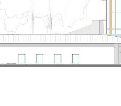
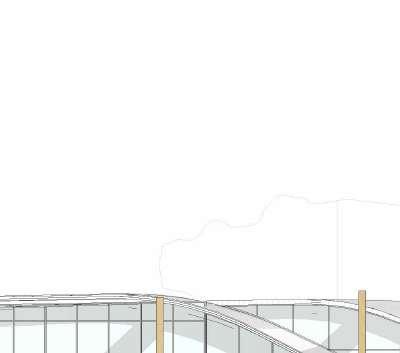
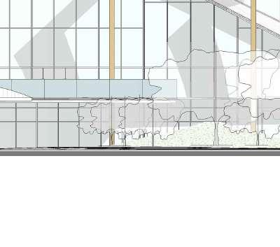
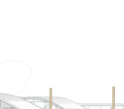
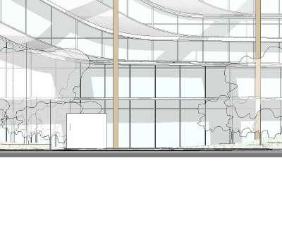
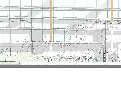

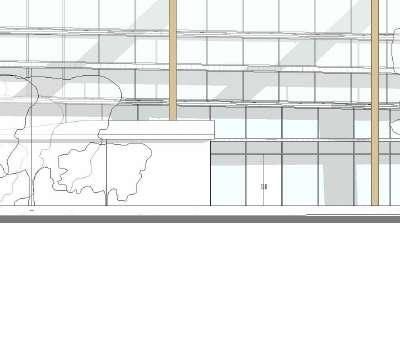


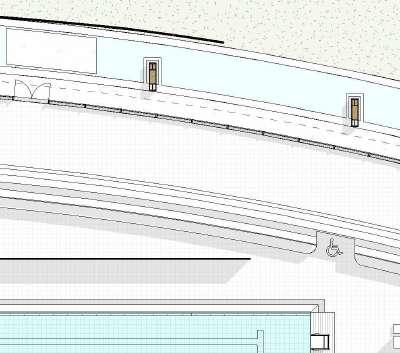
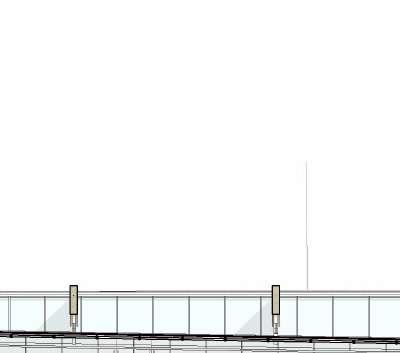
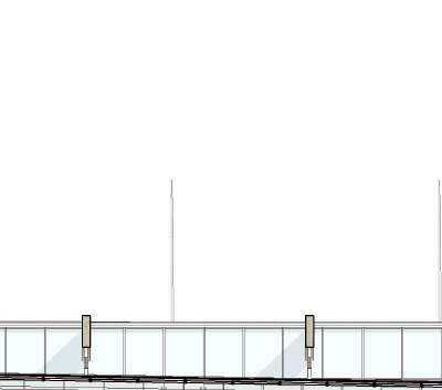
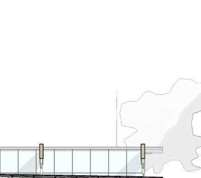
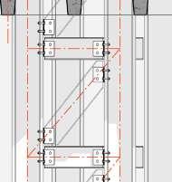
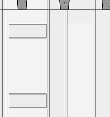
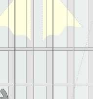
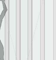
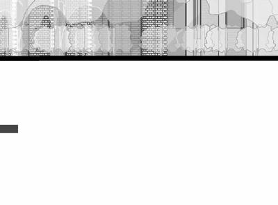
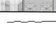
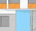
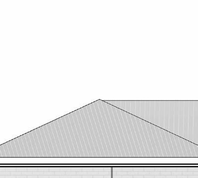
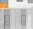
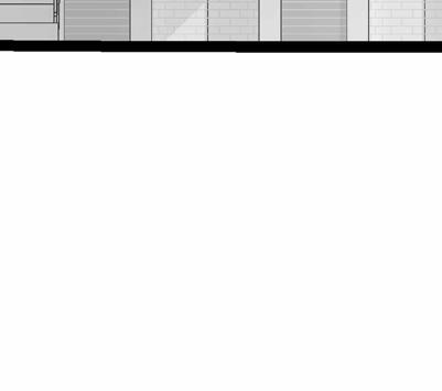
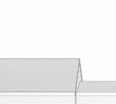
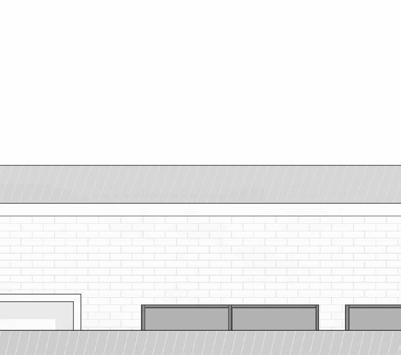
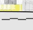
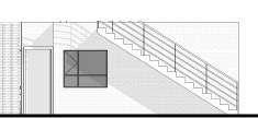
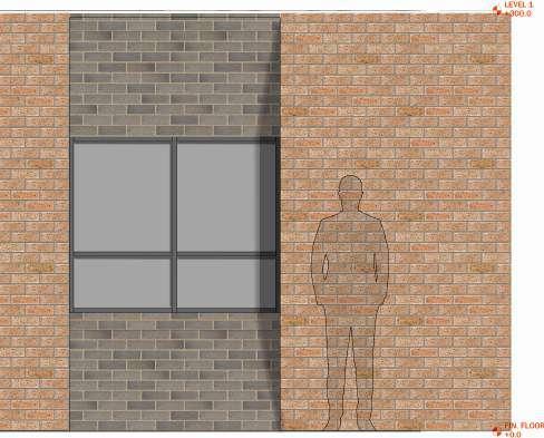
18 01 NGL LEVEL +30000 02 FFL Pavillion +33000 1 A201 03 Top Tier +36000 04 RoofPlate +39000 05 Roof Ridge +42000 1 2 4 6 7 9 3 5 8 10 11 03 Top Tier +36000 04 RoofPlate +39000 05 Roof Ridge +42000 1 2 3 5 2 DRAWING TITLE: REVIT 2024 REV DESCRIPTION TEL: 076 877 0999 EMAIL: THEMETRICDIMENSION@GMAIL.COM WEBSITE: METRICDIMENSION.MYPORTFOLIO.COM AQUATIC SCALE: 1 200 1 North SITE ANALYSIS RESPONSE MILESTONE PRESENTATION DESIGN DEVELOPMENT MILESTONE INTERIM REVIEW TECHNICAL SECTION DEVELOPMENT TECHNICAL SECTION DEVELOPMENT TECHNICAL SECTION FINAL FINAL PRESENTATION 1 A201 03 Top Tier +36000 04 RoofPlate +39000 05 Roof Ridge +42000 1 2 4 6 7 9 3 5 8 10 11 01 NGL LEVEL +30000 02 FFL Pavillion +33000 03 Top Tier +36000 +29150 04 RoofPlate +39000 05 Roof Ridge +42000 A B C D E F 2 A201 00 FFL Poldeck Gravel strip for drip Chain gutter to drain into SCALE: PROJECT NO: ISSUE DRAWING NO: PROJECT STATUS: ARCHITECT: CLIENT: DRAWN BY: STUDENT DRAWING TITLE: REVIT 2024 SHEET NO MOSS ONEL L O REV DESCRIPTION AQUATIC A301 ELEVATIONS 01 01/20/23 Author DESIGN & THEORY STUDIO UNIVERSITY OF CAPE RD, CENTLIVRES BUILDING TOWN 7700 SCALE: 1 200 1 North SCALE: 1 200 2 South SCALE: 1 200 3 West SITE ANALYSIS RESPONSE MILESTONE PRESENTATION DESIGN DEVELOPMENT MILESTONE INTERIM REVIEW TECHNICAL SECTION DEVELOPMENT TECHNICAL SECTION DEVELOPMENT TECHNICAL SECTION FINAL FINAL PRESENTATION 1:200 ELEVATIONS 0.1
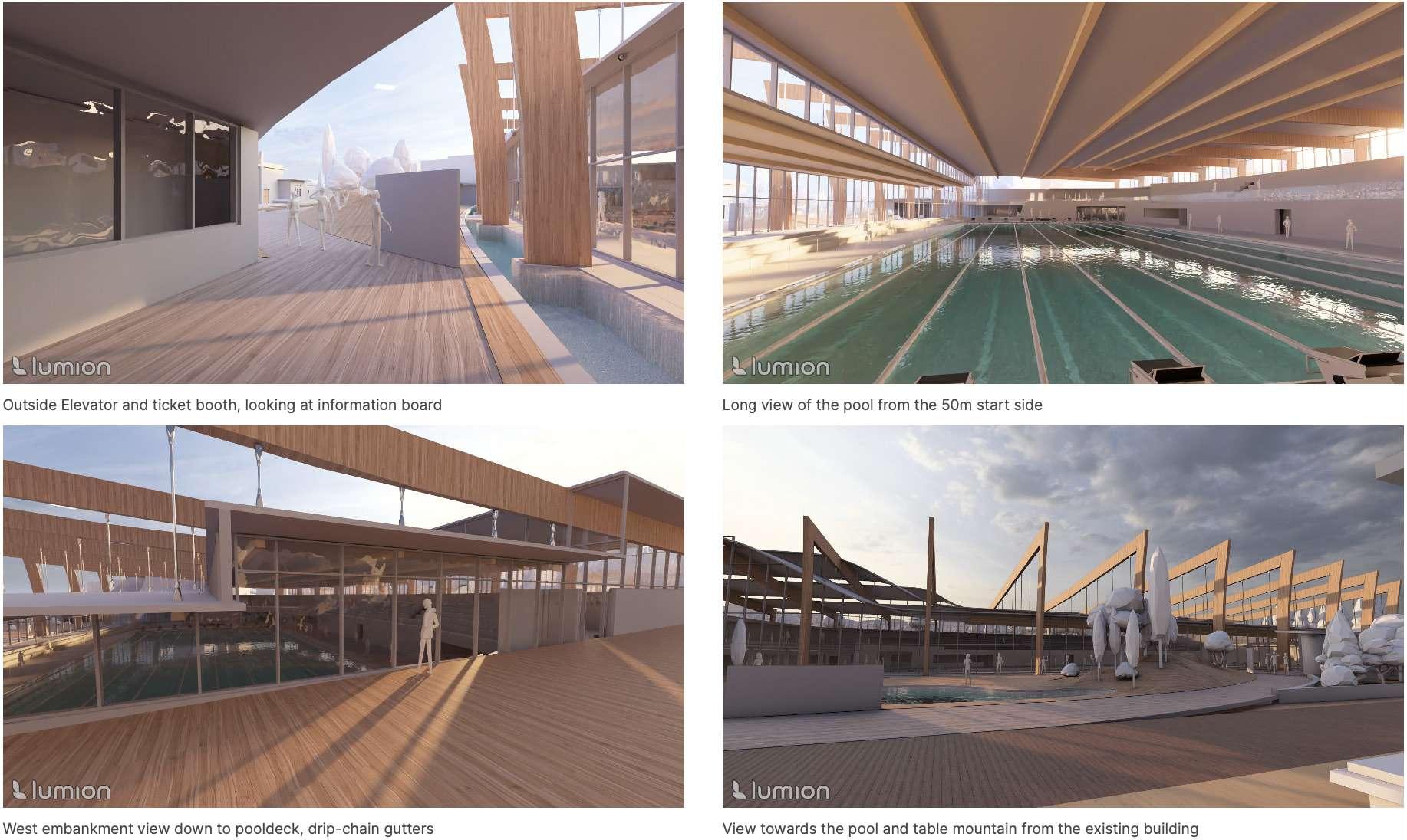
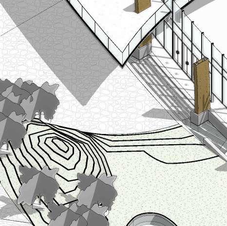
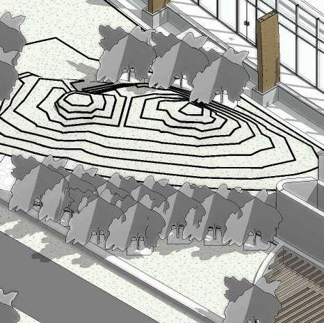
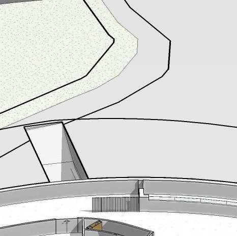
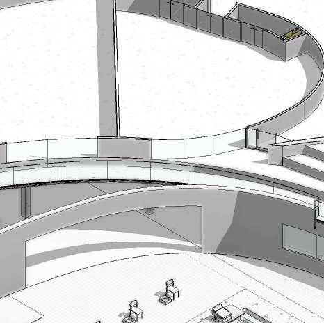
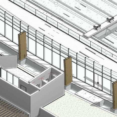
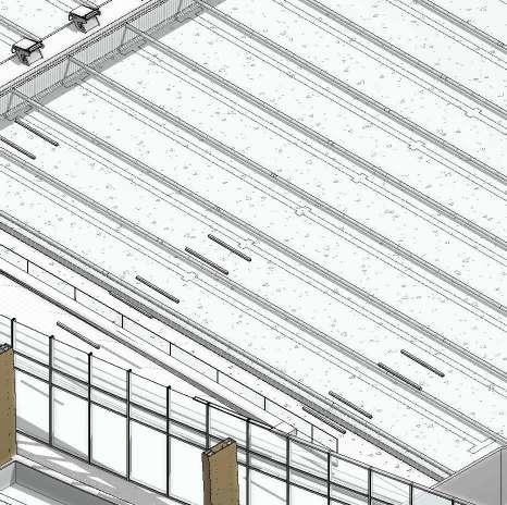
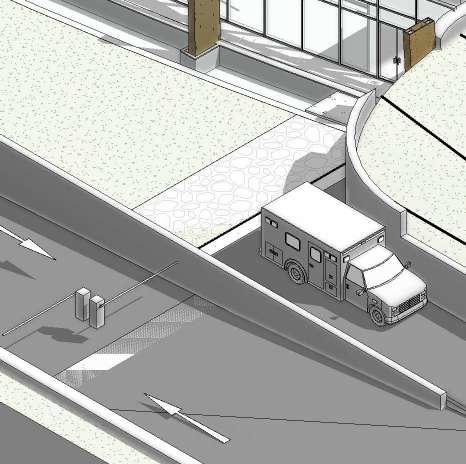
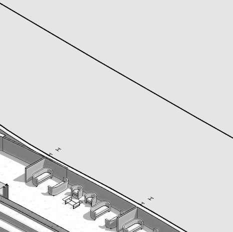
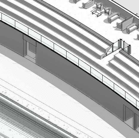
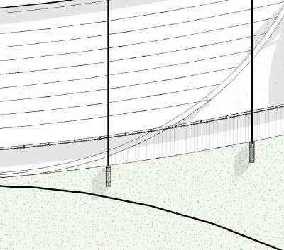
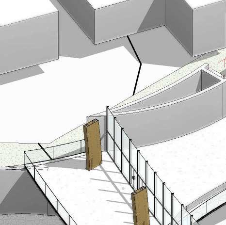
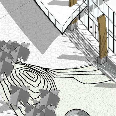
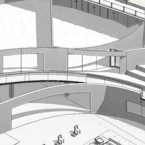
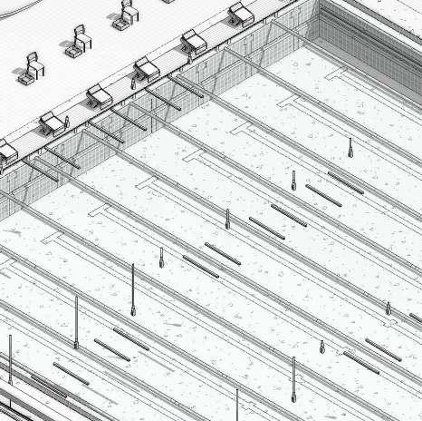
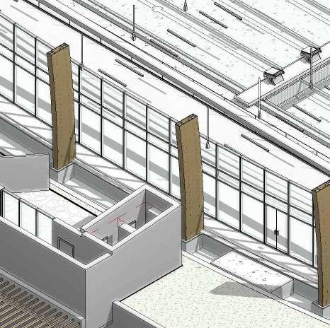
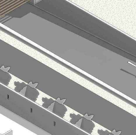
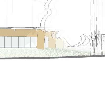
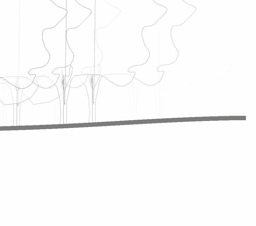
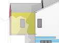
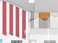
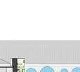
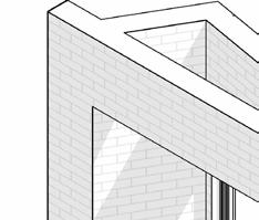
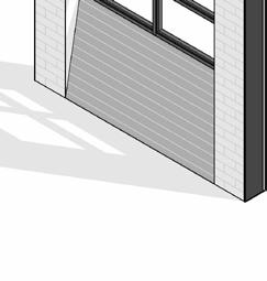
19 RENDERS 0.1
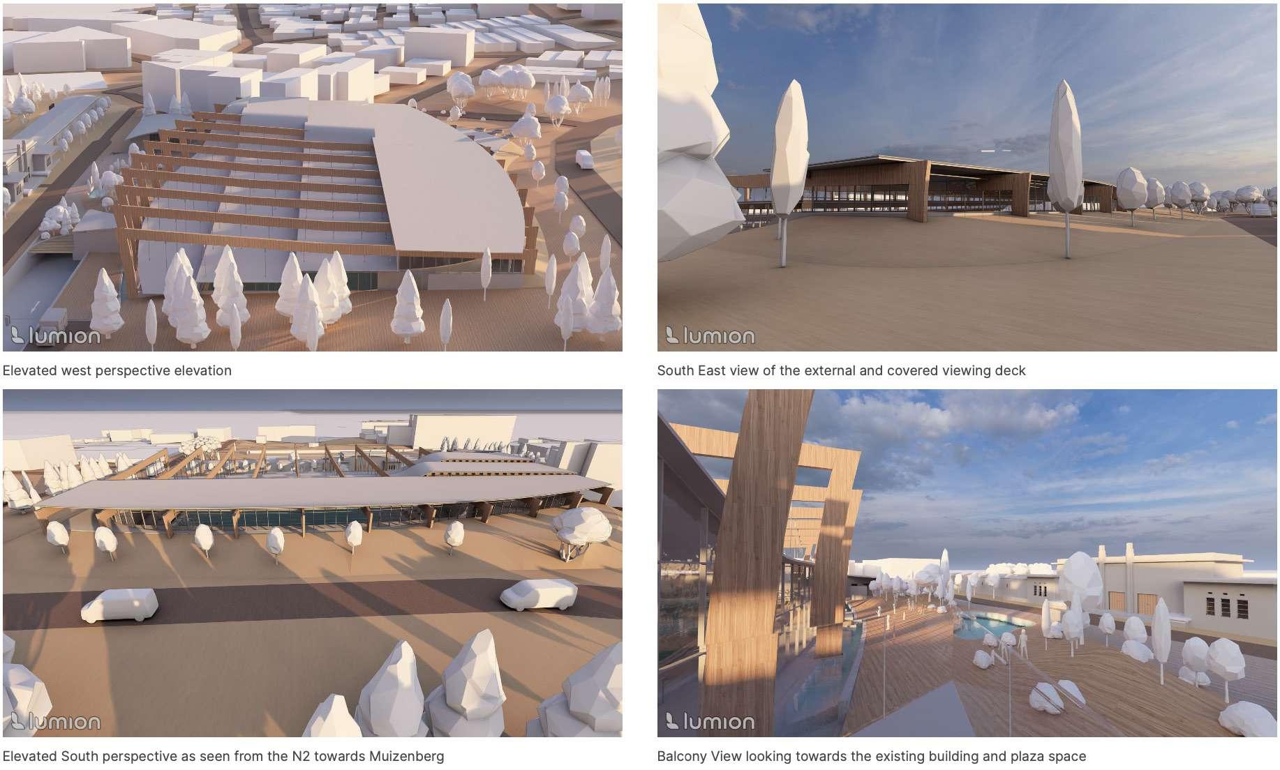
20 RENDERS 0.1
PROPOSAL DATA
NARRATIVE
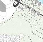
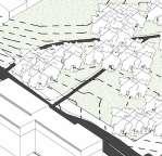
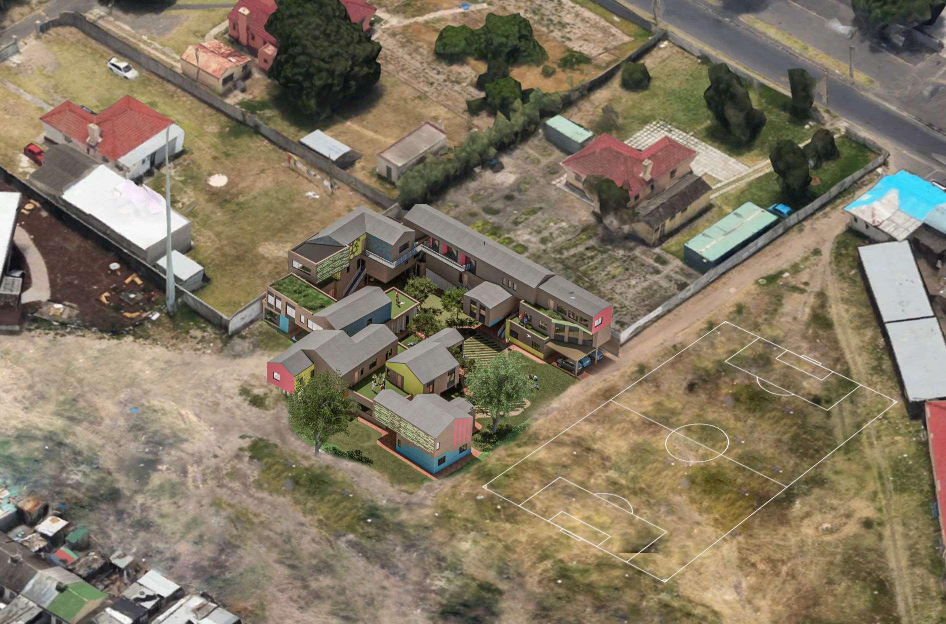
I can speak from my experience in Langa; the area consists of systems that function in their own developed way. It has been trial and error for business owners and entrepreneurs, but most informal shop owners are relatively successful in producing an income from what they manufacture themselves.
Going into this project, the underlying idea was not to reinvent systems that already work but rather to accommodate opportunities for those facets to expand.
21 PRODUCTIVE LIVING 0.2
TYPE DATE LOCATION PROFESSOR COLLABORATORS Conceptual design 28 September - 20 October2023 Langa, Cape town Barry Lewis Zoe Foale
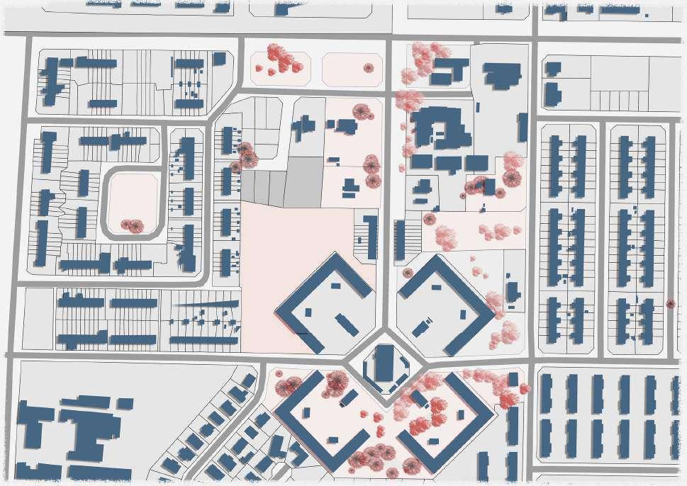
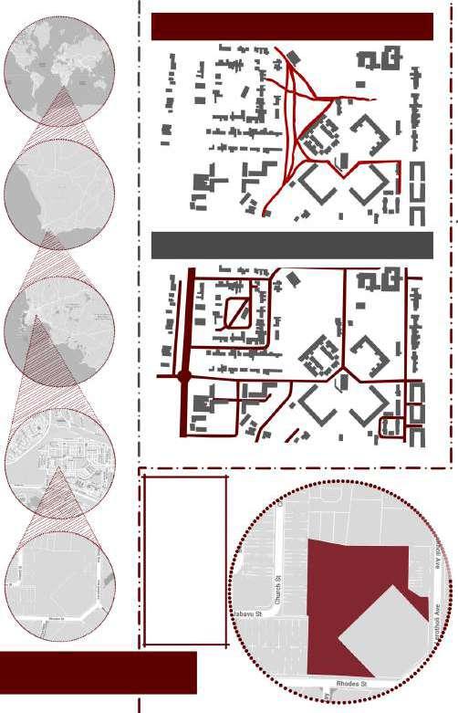
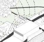
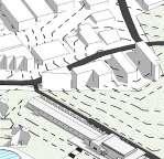
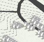
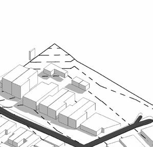
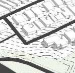
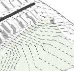
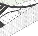
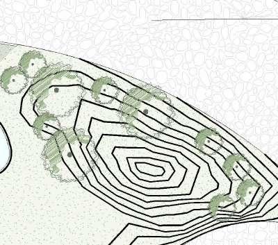
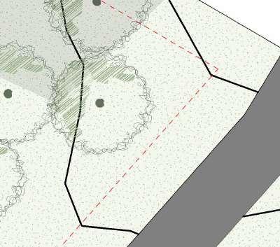
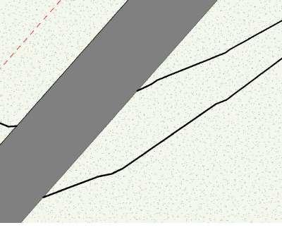
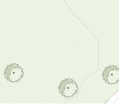
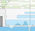
22 52 SITE 0.5 4 Ren e Luus Abby G een Maphe o Boo L one Moss Lay a Four e SITE MAP 1: 1000 1:1000 SITE PLAN 0.2 4 SUN PATH VEHICULAR CIRCULATION PEDESTRIAN CIRCULATION LOCATION S I T E B O U N D R Y S TE THE S TE IN LANGA HAS S GN F CANT PEDESTR AN C RCULATION AND SERVES AS A CENTRAL GATHER NG PLACE FOR SOC AL ENGAGEMENT W TH N THE COMMUN TY FURTHERMORE THE S TE S CONVEN ENTLY S TUATED N CLOSE PROX M TY TO MANY MAJOR ROADS W TH N THE LANGA AREA MAK NG T READ LY ACCESS BLE TO THE GENERAL PUBL C 0.2 Site Plan Scale: 1:500 1:500 SITE 0.1
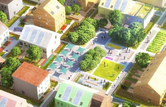
MVRDV, Rotterdam based firm
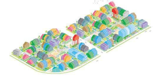
The Funari project, named after the one of five districts in the Benjamin Franklin barracks, joins housing, gardens and public spaces, in a collection of varied typologies meant to attract different types of households and demographics. The hope is that such heterogeneity will upend traditional perceptions of village life as territorial and segregated.
It’s where you know your diverse community, where the kids can run around in the street, where your home is exactly what you need it to be.
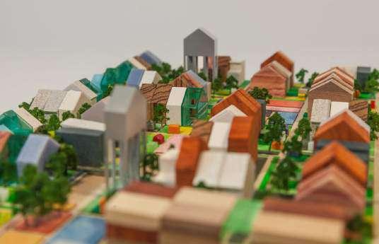
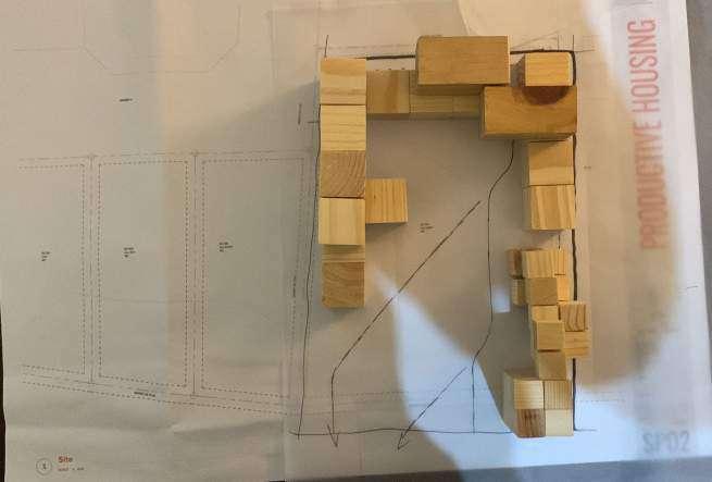
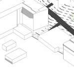
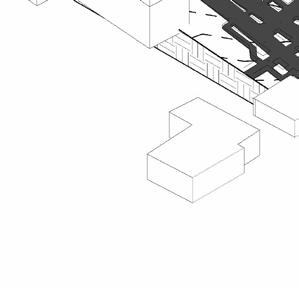
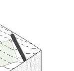
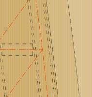
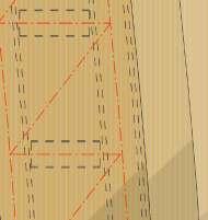
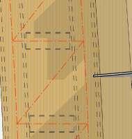
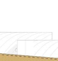
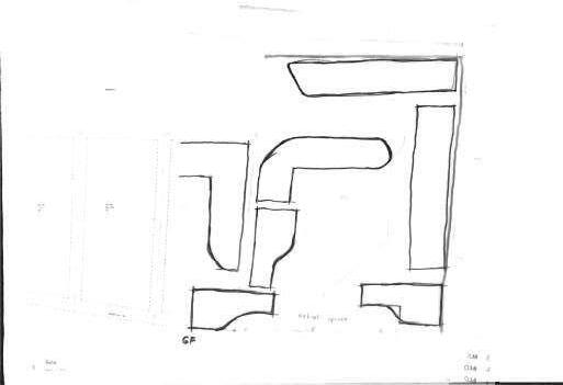
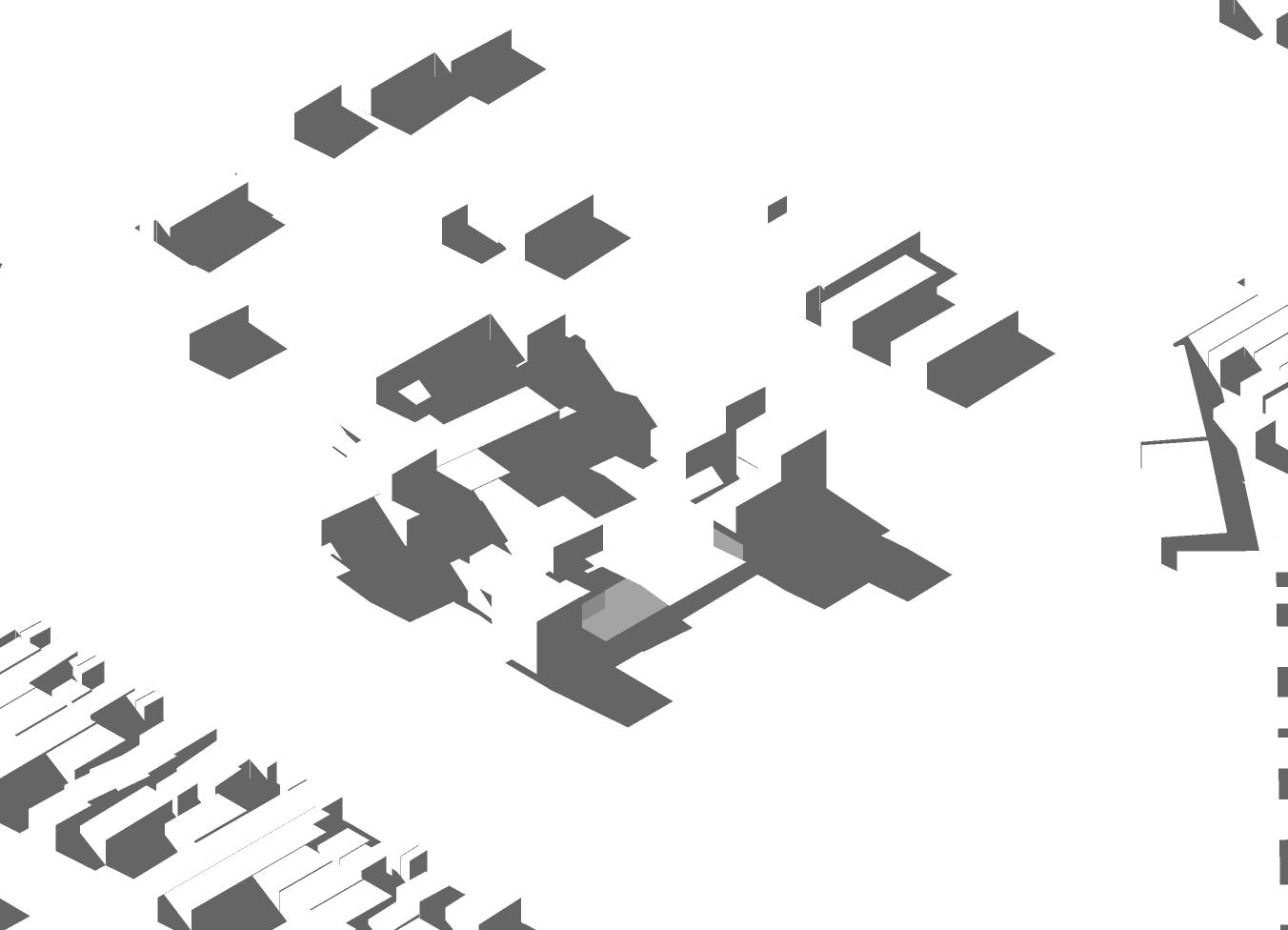
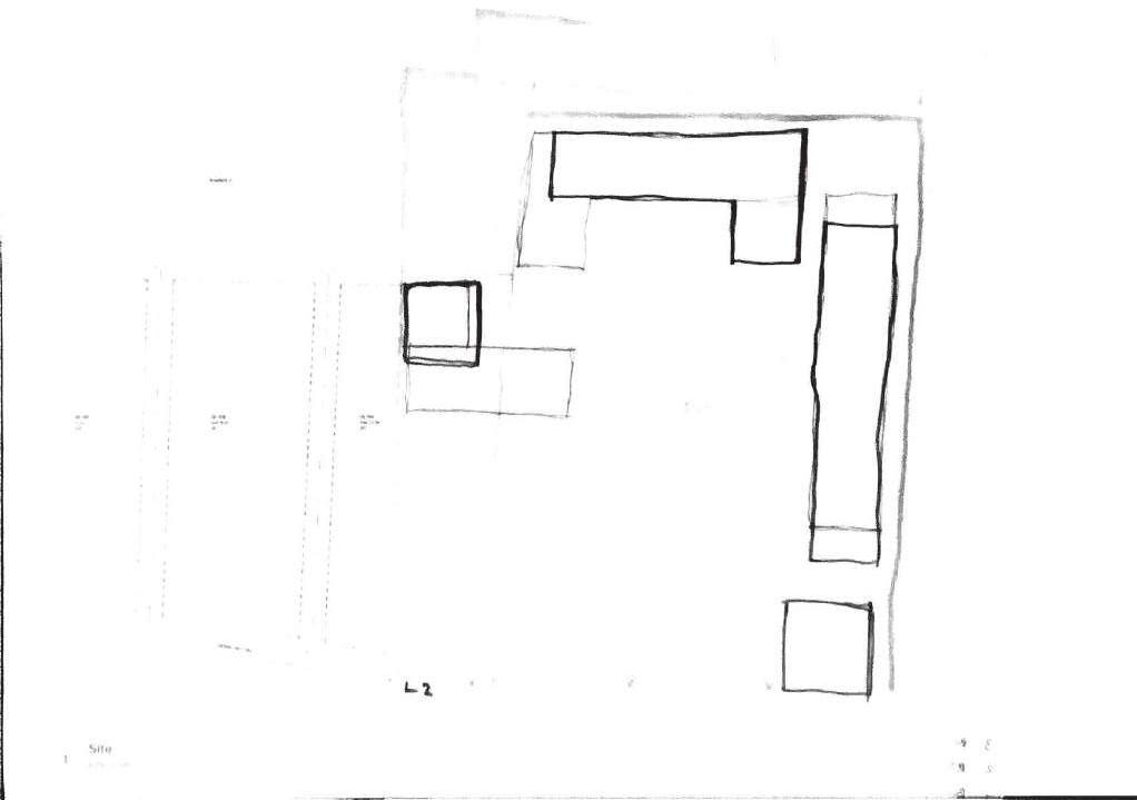
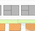
Developing my concept involved printing out a 1:200 sit plan and overlaying wooden blocks of the same scale. The blocks represent the massing of units. This was an excellent way to examine how the housing scheme would fit into the bigger context.
Unfortunately, too many units need to be placed on such a small site. The idea is to create better living conditions in Langa, not to recreate what has already happened in the hostiles.
In addition to the housing units, space should be allocated for farming, retail, deliveries and circulation.
When we entered the house for the first time, I was struck by a wave of emotions. Seeing the conditions that needed to be endured daily, what has probably been so for most of their lives, was heartbreaking.
Martha, the name of the person’s house we were invited into. The expression on her face reflected that this was not the first time tourists had walked around on her property. She had such a look of shame and sadness. She longs for better living conditions, longing for a place she can be proud of.
I propose to develop such places for Martha and other inhabitants of Langa with my productive housing scheme. I want to provide housing so they can be proud to invite tourists in and say, “Please come look inside.”
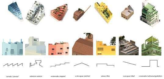
23 54 MVRDV PRECEDENT STUDIES 0.5 8 SCHEME
0.5
NARRATIVE
MVRDV PRECEDENT STUDIES 0.1
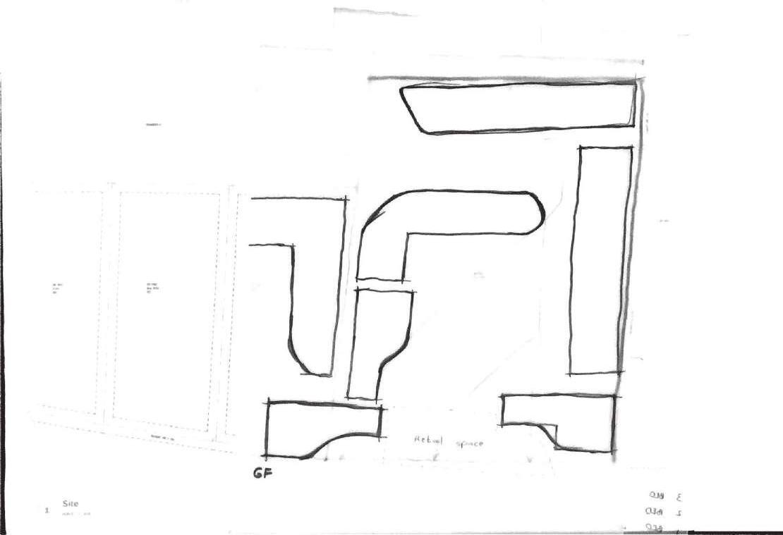
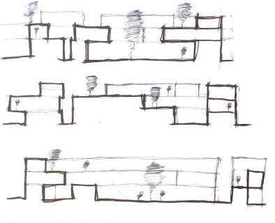
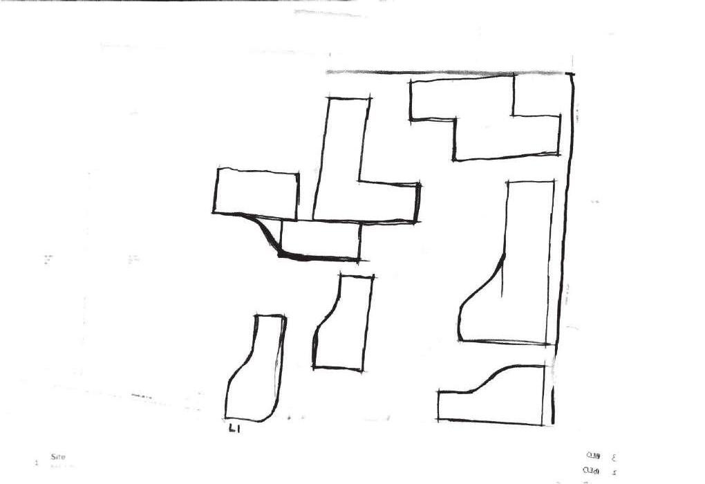
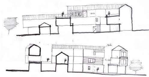
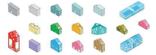
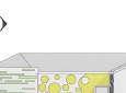
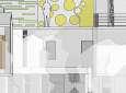
24 55 CONCEPT DRAWINGS 0.5 10 CONCEPT UNIT PLANS 1: 500 0.6 Ground Floor Flow of movement through the space Site Sections First Foor AA AA BB CC BB CC 11 SCHEME PROPOSAL AXONOMETRIC VIEWS 0.6 GROUND FLOOR FIRST FLOOR SECOND FLOOR 3 Bedroom Unit 2 Bedroom Unit 1 Bedroom Unit Retail Space PLANS SECTIONS EXPLODED AXONOMETRIC CONCEPT UNIT LAYOUT 100 0.6 CONCEPT UNIT LAYOUT 1: 100 0.6 Section CC Section AA CONCEPT DRAWINGS 0.1
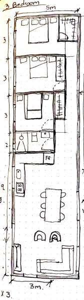
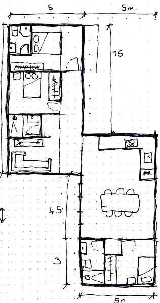
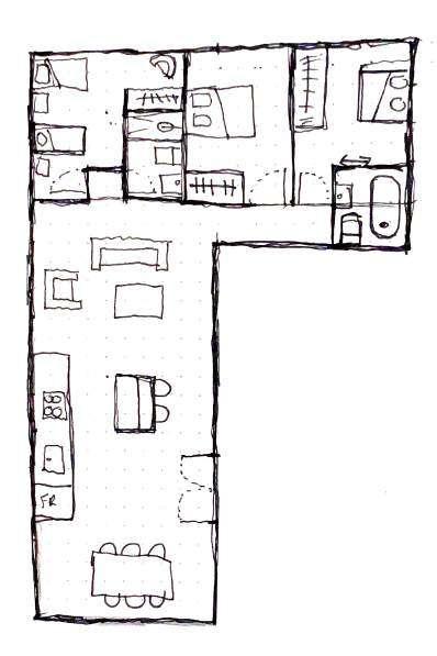
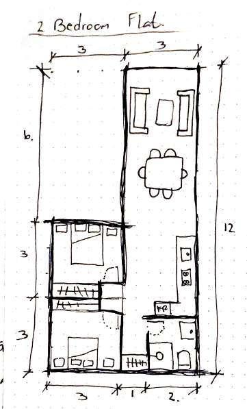
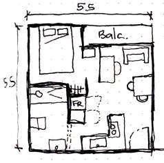
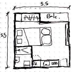
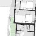
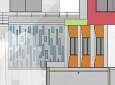
25 56 1:100 UNIT LAYOUTS CONCEPTS 0.5 1: 100 0.6 1 Bedroom Layout 12 CONCEPT UNIT LAYOUT 1: 100 0.6 1 Bedroom Layout 2 Bedroom Layout 12 13 CONCEPT UNIT LAYOUTS 1:100 0.6 3 Bedroom Layout Type A 3-bedroom for single family, with outdoor space including an urban farming component: +/- 100sqm 60% of total site area 2 bedroom as a shared household: +/- 60tsqm 30% of total site area 1-bedroom with a multi-functional space that can be used to generate additional income or future home extension: +/- 100sqm 10% of total site area Type A Type B 1:100 UNIT LAYOUTS 0.2
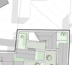
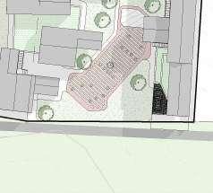


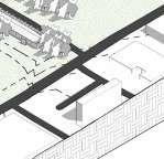
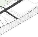
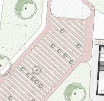
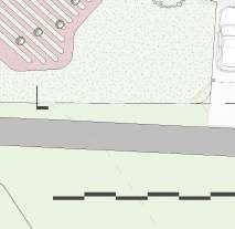
26 57 SITE & CIRCULATION 0.5 of the scheme and greater surroundings Exploded Axonometric view of circulation on ground floor and between levels GF Level1 Level 2 ERF2988 Area: 1400m2 ERF2990 Area: 367m ERF2991 317m ERF2011 ERF Area: 8829.5m REMAINDER rd Community Centre Public Park New Access point to development Proposed Developments NewRoad 0m 10m 20m 1 New Clubhouses Site section of the scheme and greater surroundings SITE PLAN & CIRCULATION 0.2


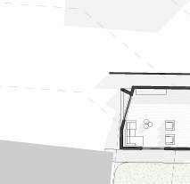
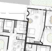
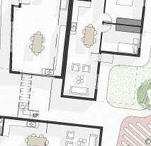
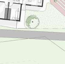
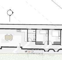
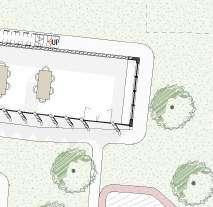
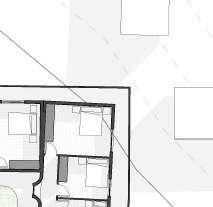
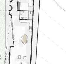


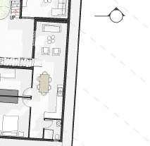


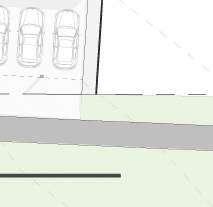


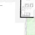
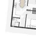
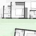


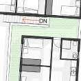
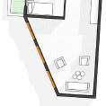


27 58 1:200 FLOOR PLANS 0.5 Unit A Unit B Unit D Unit E Unit C Unit F Unit G Productive living Workshop & retail Space Water New access point Driveway A B 0m 10m 20m New Road Balcony Unit H Unit I Unit J Unit K Unit L Unit M Unit N Balcony Balcony Balcony Balcony Balcony Balcony A B Ground Floor plan Scale: 1:200 First Floor Plan Scale: 1:200 1:200 FLOOR PLANS 0.2


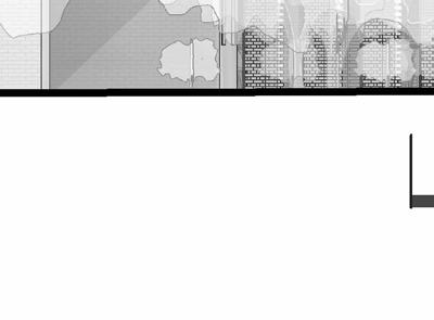


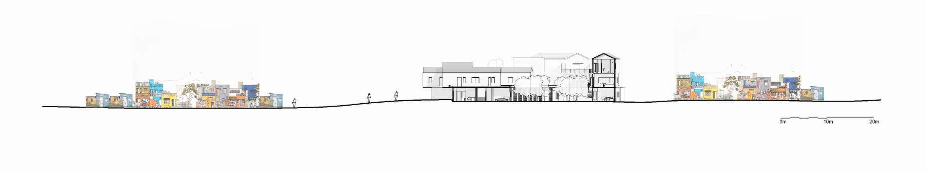
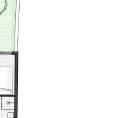
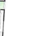
28 59 1:200 FINAL DRAWINGS 0.5 Unit O Unit P Unit Q A B Second Floor Plan Scale: 1:200 Views to Devil’s Peak Section BB Scale: 1:200 South Elevation Scale: 1:200 0m 5m 10m A 0m 5m 10m A 1:200 FINAL DRAWINGS 0.2


29 60 0m 5m 10m B Market Space 0m 5m 10m B Section AA Scale: 1:100 West Elevation Scale: 1:100 1:100 FINAL DRAWINGS 0.5 1:200 FINAL DRAWINGS 0.2


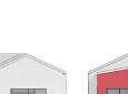
I initially started with three basic unit layouts that followed the shape of their corresponding Box in the concept model.
As the scheme developed, each unit had to morph from the” base’ design to suite it’s location and use better.


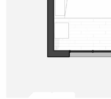
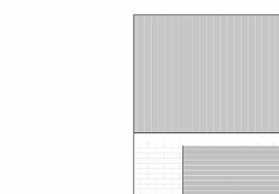
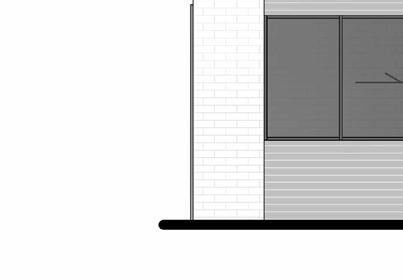
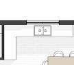

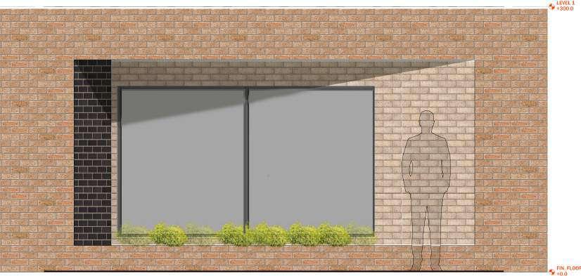


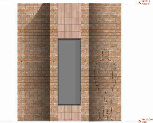
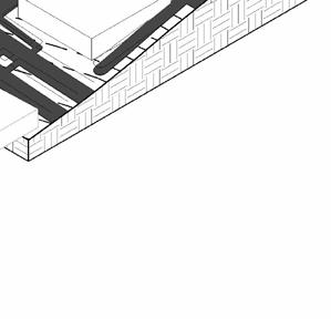
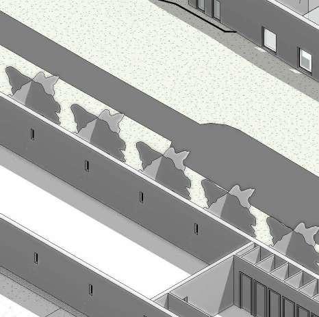
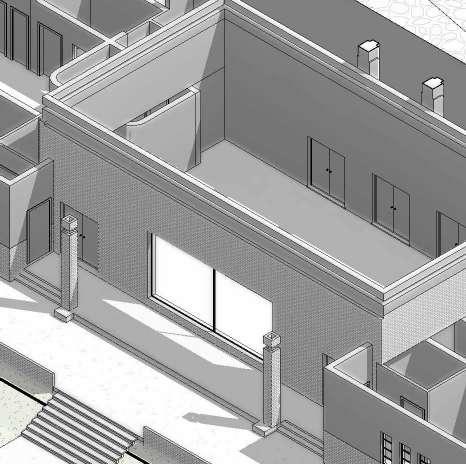
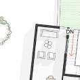
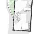
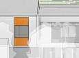
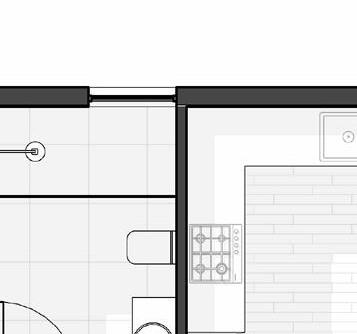
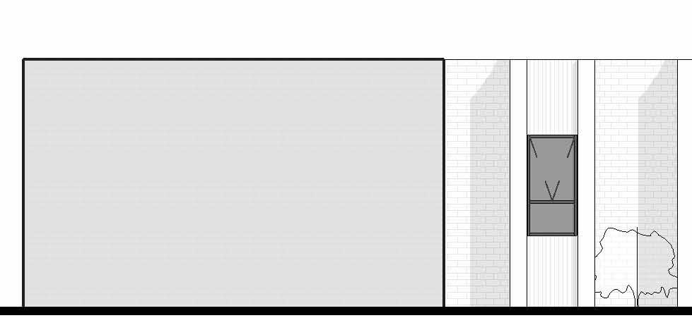
30 61 UNIT LAYOUTS & BRICKWORK ELEMENTS 0.5 Exposed brick pattern Feature Window 3 Unit A Staircase to Unit above Feature window 1 Featurwe window 2 Decorative wall feature 13 m² Bedroom 2 Timber 9 m² Bedroom 1 Timber 13 m² Living Timber 15 m² Kitchen Timber 3 m² Bath Tile BIC BIC 12000 7300 7200 �3500 Enterance Unit L Unit D 3 m² Bathroom Tile 5000 10000 3200 16 m² Bedroom timber 20 m² Kitchen & Living Timber Workshop Bay window seating Enterance Workshop Feature window 2 Unit B 15 m² Master Bdroom Timber 9 m² Bedroom 2 Timber 9 m² Bedroom 3 Timber BIC BIC BIC 5 m² Bathroom Tile 25 m² Living Room Timber 24 m² Kitchen Tile 11 m² Hallway Timber Staircase to unit above Roof overhang which creates threshold moment for lower unit Unit A Decorative brick feature along Feature Wall 4975 23800 3750 3000 3000 2000 1200 3800 5000 Facade Elements Scale: 1:20 Facade Detail 1 Facade Detail 2 Facade Detail 3 3 Bedroom Unit Layout & Elevation Scale: 1:100 2 Bedroom Unit Layout & Elevation Scale: 1:100 1 Bedroom Unit Layout & Elevation Scale: 1:100
UNIT LAYOUTS & BRICKWORK ELEMENTS 0.2

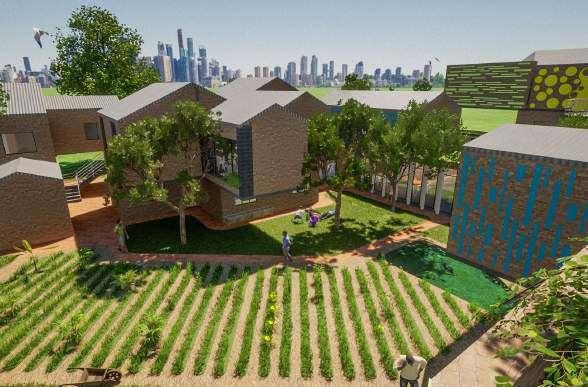
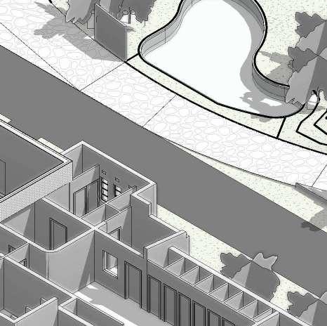
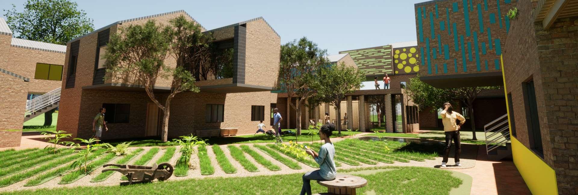
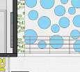
31 62 EXTERIOR RENDERS 0.5 RV2 - Ground Floor view of the productive living area RV3 - Third floor level of the central circulation space RV1 - Axonometric View of the building in context RENDERS 0.2
32 v Thank You