Washington University School of Medicine
Facilities Conditions Report
Asset B181 Biotech Building
17 September 2024


Washington University School of Medicine
Facilities Conditions Report
Asset B181 Biotech Building

17 September 2024


Asset Name & Number B181 Biotech
Address 4959 Scott Avenue; St. Louis, MO 63110
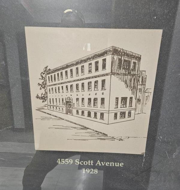
Date of Original Construction 1927 ( Jamieson & Spearl Architects)
Gross Area 94,067 GSF
Primary Use + Function Medical Labs and Office Building
Current Replacement Value $66,586,603 (WUSM FY24 CRV Report)
It is the goal of the team to conduct a limited Facilities Condition Assessment of Building B181 Biotech reviewing the condition of all identified spaces utilizing a grading scale provided by Washington University School of Medicine (WUSM). The team will also provide Site, Building Envelope, MEPFP system, Accessibility and Code analysis for all spaces identified and create a cost estimate for any upgrades and revisions identified and needed to upgrade any space to current building code and the School of Medicine standards.
All structural shall reference the 2021 B181 Biotech Building Profile supplemental Washington University School of Medicine input.
This report was prepared by Lamar Johnson Collaborative, Inc.
Architecture & Interiors Lamar Johnson Collaborative, Inc.
Cost Estimating Moss Construction Cost Management
Structural n/a*
Envelope TAG
MEP/FP McClure Engineering
Accessibility & Code Lamar Johnson Collaborative, Inc.
*Supplemental information provided by Operations & Facilities Management Department at Washington University School of Medicine
This report was generated in good faith through a compilation of visual site observations, existing document review, user interviews and previously generated reports, components and information provided by others. Comments, recommendations & identified building deficiencies from previous reports that had not been addressed or remedied at the time of this report have been carried over to this report. These primary documents include, but may not be limited to:
Building Scan
Testing, intrusive observations and exploratory demolition were out of the scope of this report. While ASTM E2018-15 provided guidance on the scope and organization of this report, this report shall be considered a Facilities Conditions Report as opposed to a Property Conditions Report due to the request that recurring as well as non recurring costs have been included through the year 2034. In addition, this property conditions assessment has been conducted under the assumptions that major interior renovations would be completed as part of any remediation activities. While all reasonable effort has been made to capture the full breadth of scope to bring this building up to Washington University School of Medicine standards & code enforced regulations, it should be noted that previous studies were completed to address renovations, demolition & rebuild, and decommissioning. The cost associated with maintaining the building to function as is, with no extensive renovations cannot fully address all issues. Items may appear in multiple sections as some items’ impact is greater than one discipline.
At the time of this report’s writing, the City of St. Louis (who is the Authority Having Jurisdiction) has adopted the 2018 ICC suite of building codes as well as ANSI 117.1 2009 pertaining to accessibility. The comments and recommendations within this report use these codes and standards as the reference point. At this time, there is no known date for adoption of future codes nor known impacts to the recommendations within this report.
These costs are cyclical and include major repairs or replacement of major building systems that can be predicted and planned. An example of this type of item is a roof that has reached the end of it’s normal and useful life.
These costs include repairs or modifications necessary to comply with Accessibility or Fire and Life Safety code requirements. They also may address non recurring deficiencies that could negatively affect the facilities structure or building systems.
(1) A “path of travel” includes a continuous, unobstructed way of pedestrian passage by means of which the altered area may be approached, entered, and exited, and which connects the altered area with an exterior approach (including sidewalks, streets, and parking areas), an entrance to the facility, and other parts of the facility.
(2) An accessible path of travel may consist of walks and sidewalks, curb ramps and other interior or exterior pedestrian ramps; clear floor paths through lobbies, corridors, rooms, and other improved areas; parking access aisles; elevators and lifts; or a combination of these elements.
(3) For the purposes of this document, the term “path of travel” also includes the restrooms, telephones, and drinking fountains serving the altered area.
(1) Alterations made to provide an accessible path of travel to the altered area will be deemed disproportionate to the overall alteration when the cost exceeds 20% of the cost of the alteration to the primary function area.
(2) Costs that may be counted as expenditures required to provide an accessible path of travel may include:
(i) Costs associated with providing an accessible entrance and an accessible route to the altered area, for example, the cost of widening doorways or installing ramps;
(ii) Costs associated with making restrooms accessible, such as installing grab bars, enlarging toilet stalls, insulating pipes, or installing accessible faucet controls;
(iii) Costs associated with providing accessible telephones, such as relocating the telephone to an accessible height, installing amplification devices, or installing a text telephone (TTY);
(iv) Costs associated with relocating an inaccessible drinking fountain.
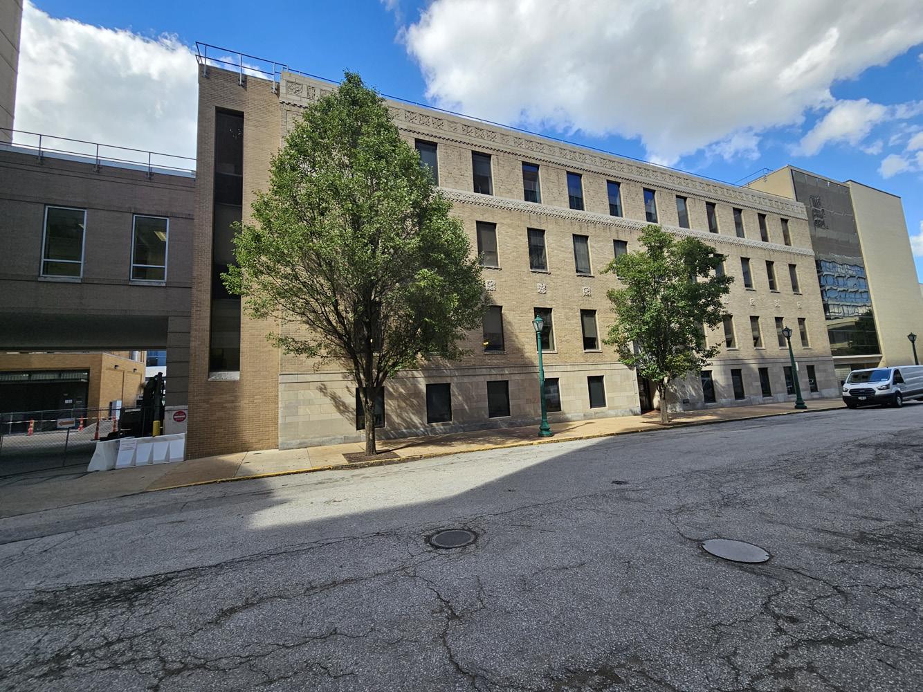
The Biotech Building sits along the North side of Scott Ave, bound by a driveway and 2nd floor connection to FLTC to the West and connected to the East Building with a link on the East side with the Metrolink running along it’s North boundryline. This report includes the building itself, along with the adjacent sidewalk and pavement areas immediately surrounding the building. The metered street parking out front supports 40+ stalls including 4 ADA stalls just East along with an additional 11 stalls across the street to the South/ South East and is accessed by an ADA curb cut with proper markings. The property has level and sloped gravel/ rock area and steam pipes separating the building site from the Metrolink rail line to the North..
The landscape adjacent to the building includes 1 40’ tall street tree along with 2 30’ street trees surrounded by flush open tree grating. The plantings seem to be in good health.
The West side has poured in place concrete driveway that was under construction during the time of our site observation, but appears in good condition otherwise. The North side site consists of gravel and a sloped grade with rock, along with poured concrete walkway/ stairs that seems to be in decent condition. This area is separated by a chain link fence with a lockable gate..
Observations
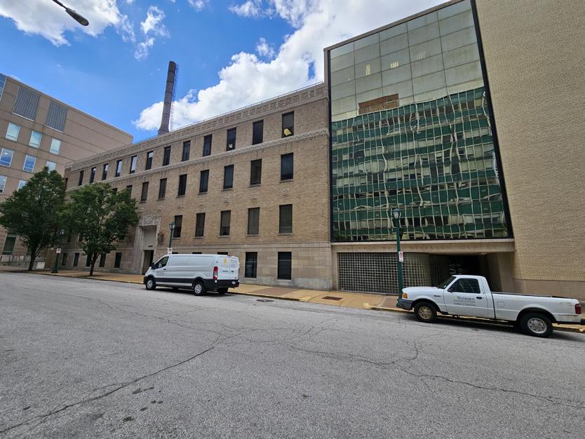
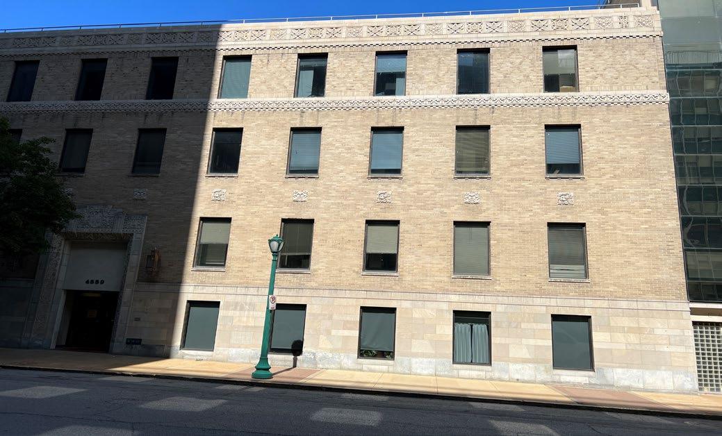
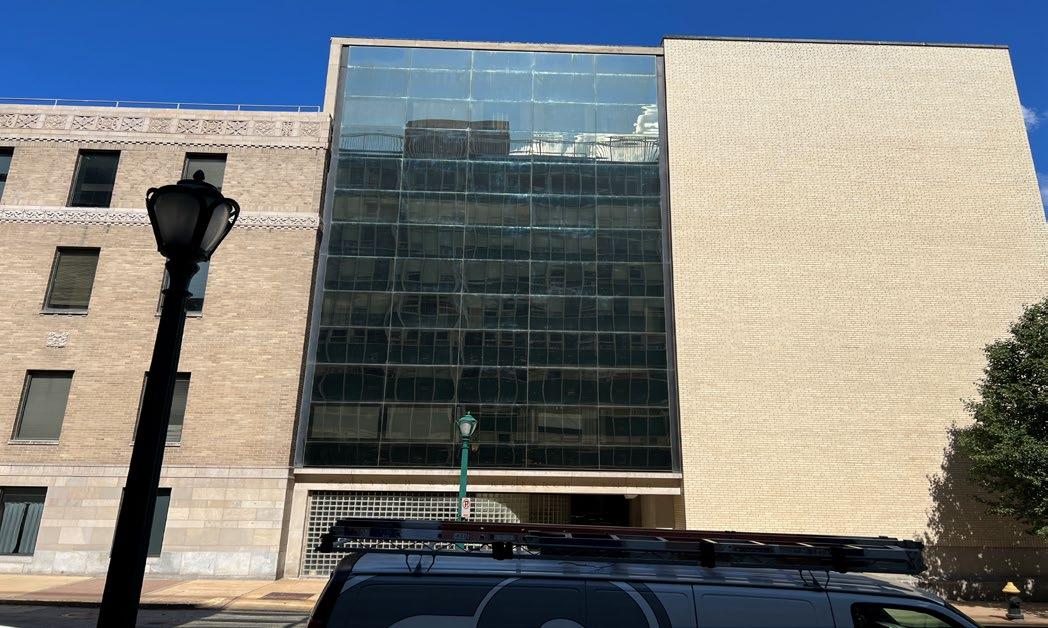
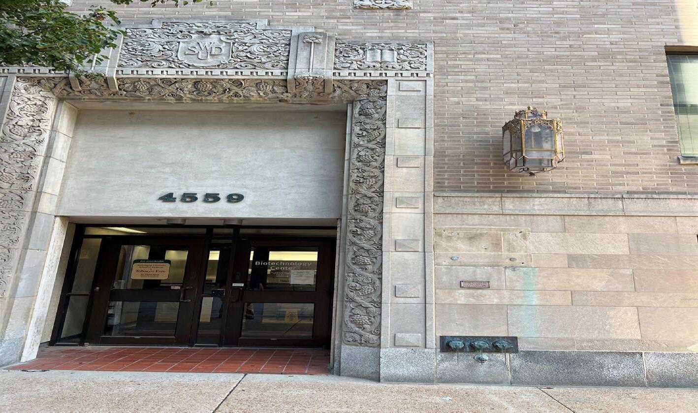
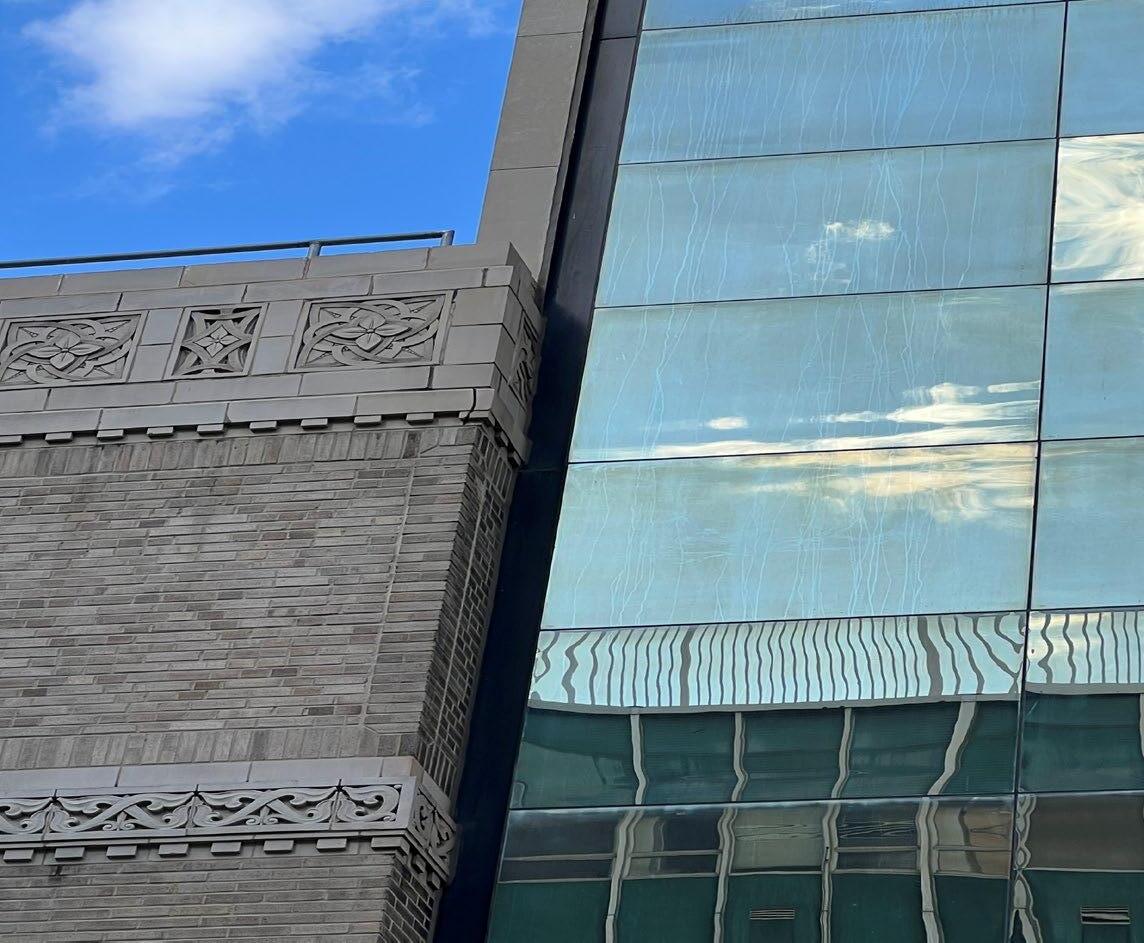
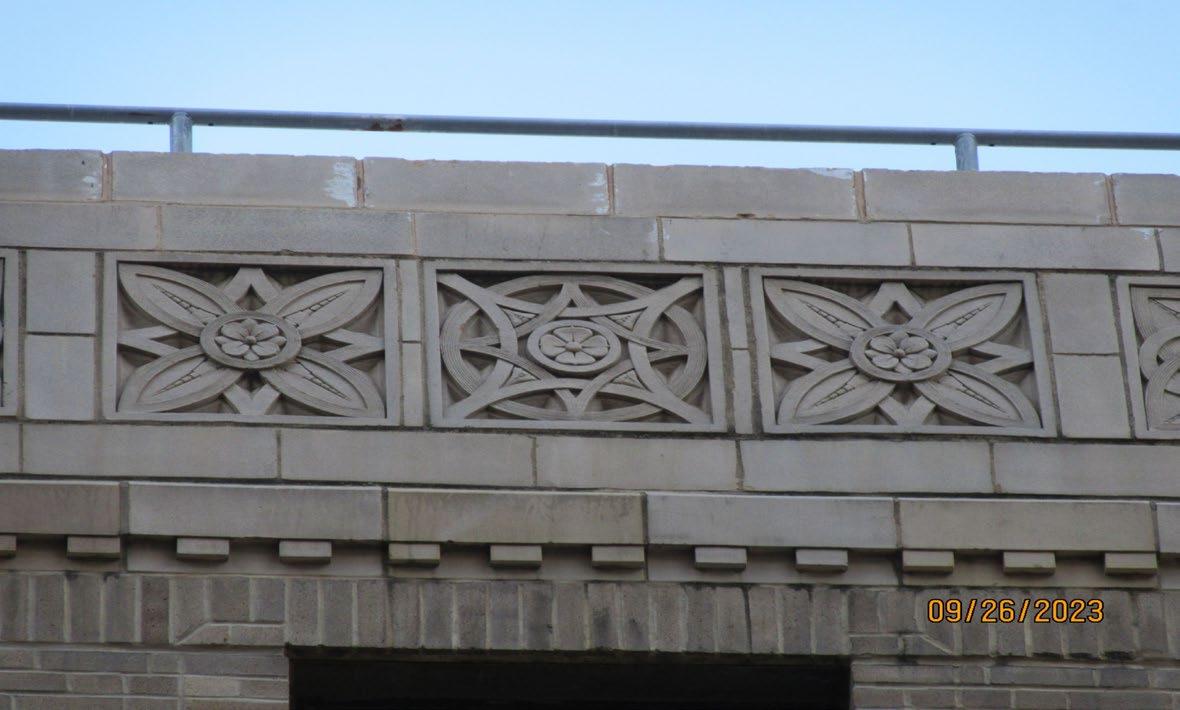
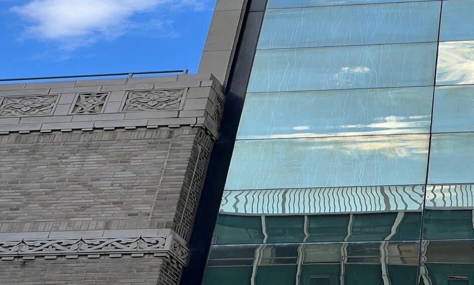
The #181 building, Biotechnology Center, is a four-story facility constructed in 1927, expanding in 1933 and 1934 with a later addition/ infill to its East built in 1961, 1969, and 1974. Approx. square forage is 94,000 gsf and the primary use is identified as Biotechnology. The two buildings look distinctively different with the exterior material of the original 1927 building a combination of face brick and limestone detailing throughout providing a historic appearance. The 1961/69/74 addition is a combination of structurally glazed curtain wall (No exterior framing members), face brick and glass block at the ground level entrance. The 1927 building has a very strong historic appearance with some intricate limestone and terra cotta detailing as a primary feature of the building. In both buildings very few brick weep holes or vertical expansion joints were visible.
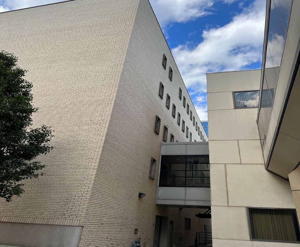
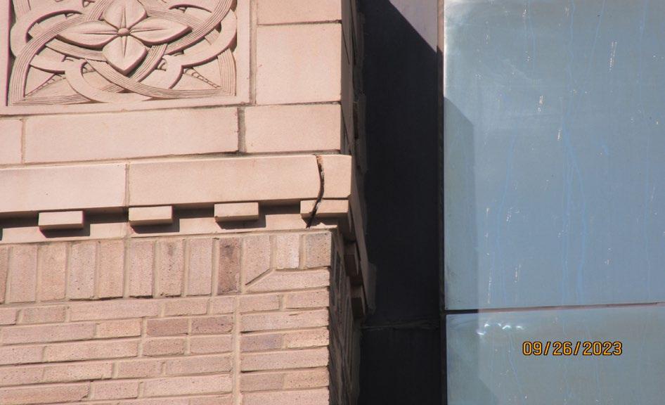
The 1927 building has only the north, south and west elevations visible. There is a bridge connection on the west face of the 1927 building to building #098.FLTC, the bridge was not inspected. The 1961 building has the north, south and partial east elevations visible, the two buildings connect at the E-W side. The interface between these two buildings has a 10” wide aluminum clad recessed closure, the horizontal joints of which are open and require new sealant. The 1961 addition connects via a bridge with the East Building. The 1927 building has a recent single story CMU addition on the north side.
The windows in the 1927 building are a newer fixed window anodized aluminum system as punched openings, typical on the west and north elevations as well. The limestone accents occur at the entrance surround, windowsills and upper cornice while limestone and granite at the building base. The roof level wall coping stone may be terra cotta. The entrance doors are a newer aluminum storefront system in good condition.
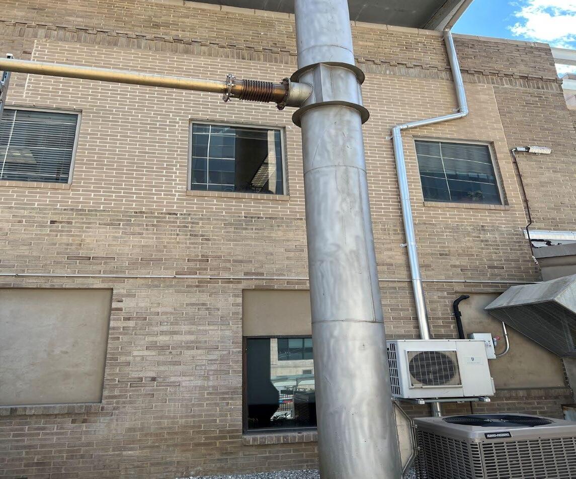
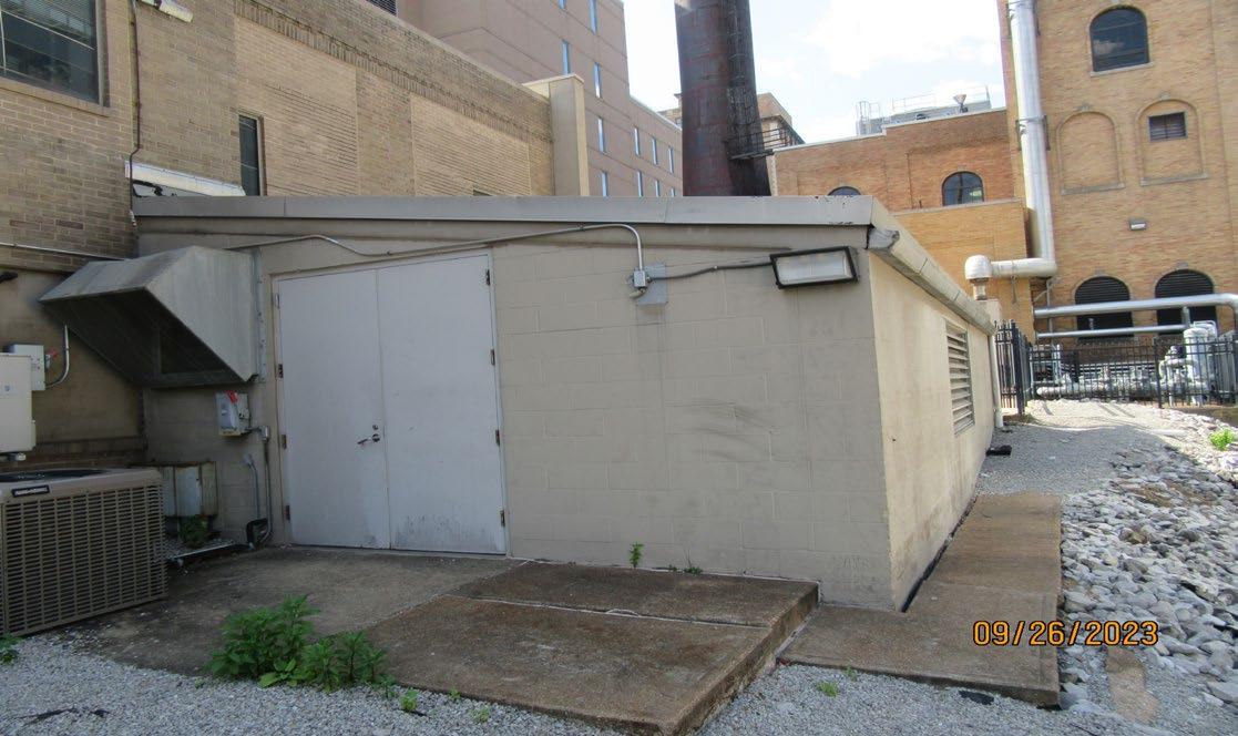
There is a small brick addition to the west in excellent condition which appears to have been constructed with the FLTC Bridge link. There are several locations of non-matching brick infill work on the north wall from previous building modifications. On the partial west and north sides there is a textured stucco like cladding of varying height with minor cracking that have been sealed, overall in good condition. The stucco wall cladding installation date is not known, but it appears to be covering original stone foundation and
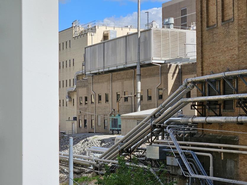
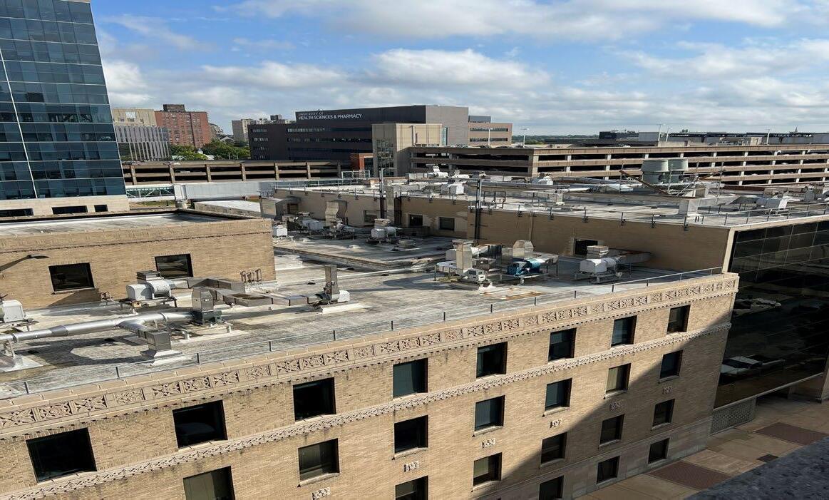
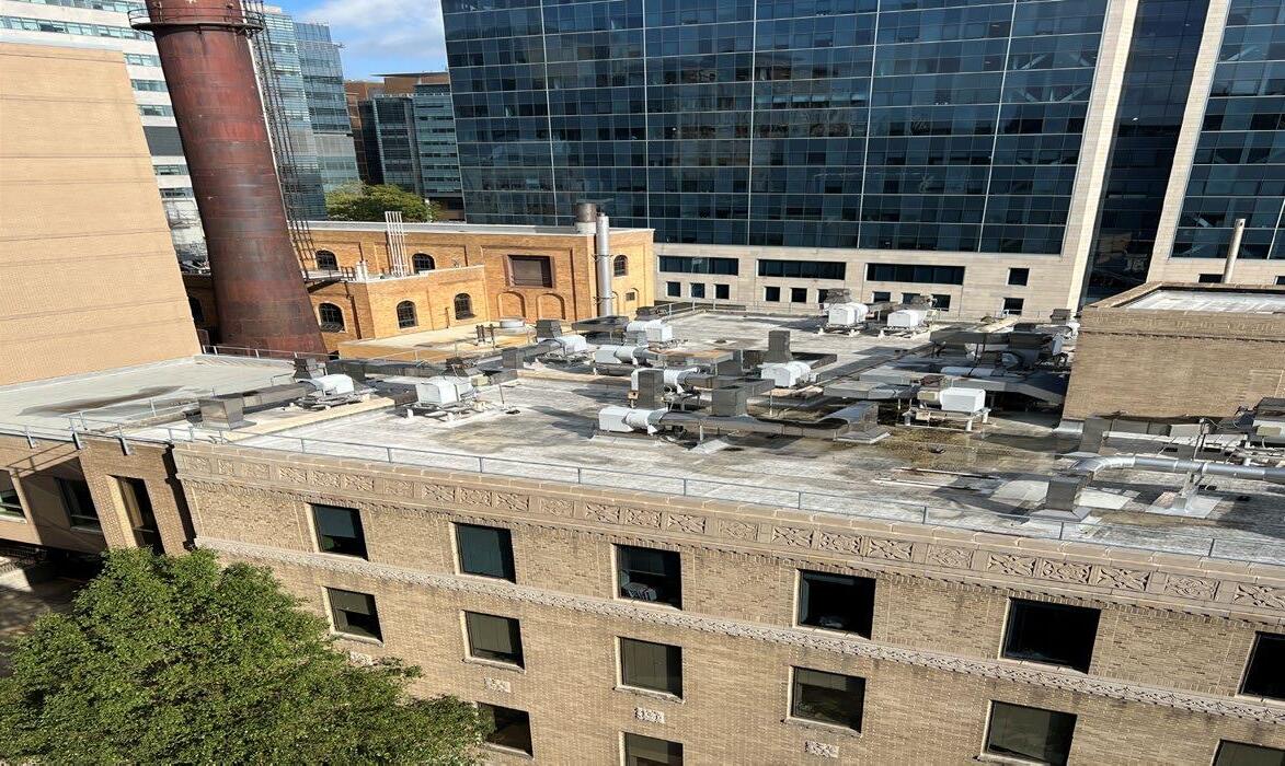
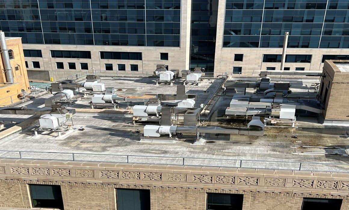
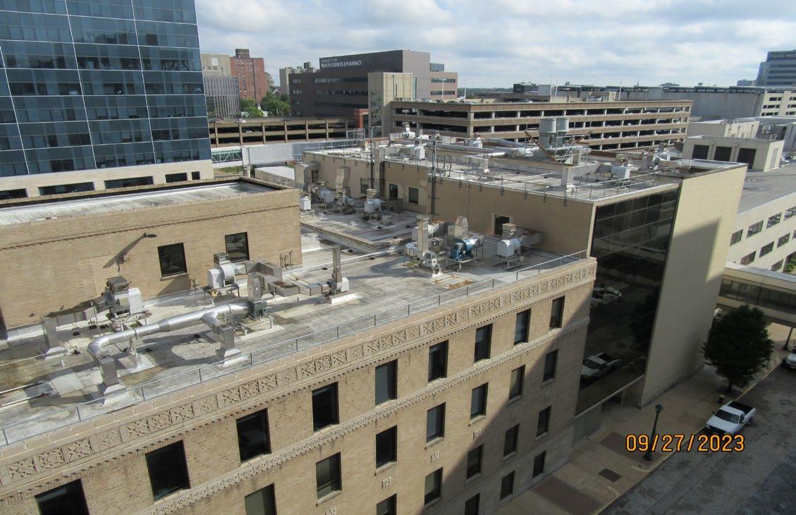
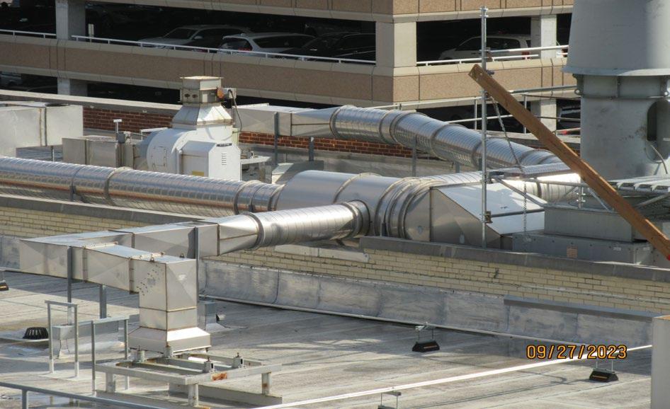
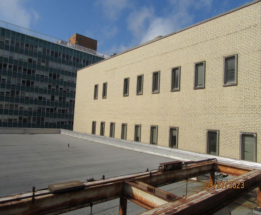
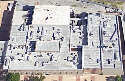
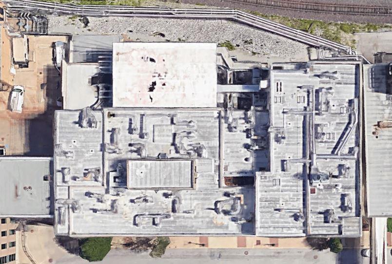
brick masonry exterior walls as observed from the interior. Due to the potential air quality of the exhausted air at roof level of building #181, the assessment team did not “walk” the roof. The roof was inspected via binoculars from the roof of the adjacent McDonnell building, #012. The roof has a heavy concentration of exposed mechanical equipment, exhaust fans, piping and exposed duct work.
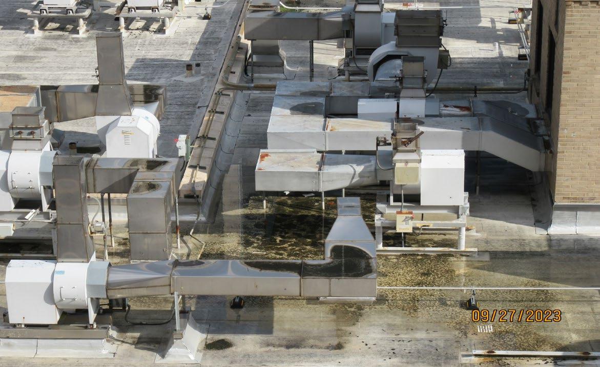
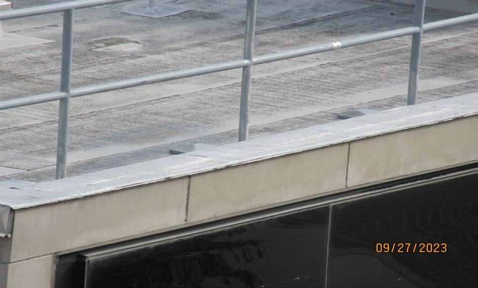
The roof is a light colored modified bituminous system (installed in 2011), with the roof pitched to internal drains. There is a fixed fall protection system in place. It appeared the roof was accessed via internal stairs. Water ponding was observed as was some organic growth at the roof drains and other areas of the roof. This indicates a low sloped or obstructed roof slope and needs to be corrected to drain the roof. There is extensive mechanical equipment mounted on the roof which contributes to the water ponding in areas as water is not flowing around the numerous equipment support curbs. Any slight depressions in the roof insulation over time will add to this ponding problem
In summary the modified bituminous roof system; seams, curbs, flashing etc should be regularly monitored to extend its useful life by identifying and addressing areas where potential water infiltration could occur. The continued ponding can be addressed by installing crickets around the curb obstructions. The roof drains should be cleared of debris. Staff will need to verify if the roof system is still under warranty. The high concentration of equipment on both roofs will make roofing replacement difficult and costly. This applies to both the 1927 and 1961 buildings. The roof system is 25 to 30 year roof if properly maintained.
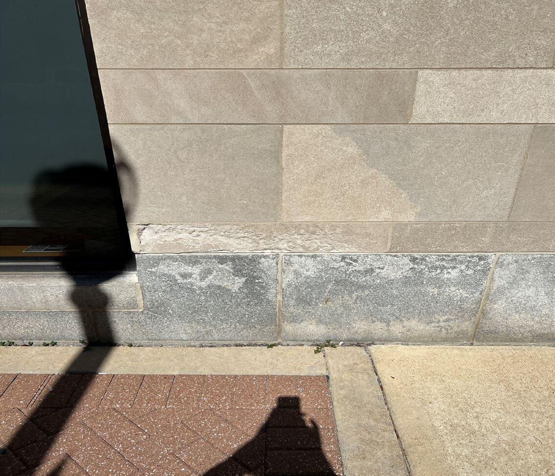
The building base is comprised of granite stone at the walk level and limestone in various sizes above to a height of 10’. The granite base has sealant joints and appear intact, the limestone has mortar joints and are in fair condition. Both the granite and lower limestone have surface deterioration and staining due to continued exposure to salt applied to the walks. The sealant joint at grade between the walk and building face should be removed, cleaned and re-sealed.
Overall the exterior face brick is in fair condition. The exception is along the north wall where numerous areas of the brick joints need to be re-pointed more so on the upper wall but seen throughout. Recommend re-pointing the entire north wall using the same color mortar to provide better weather protection and a more uniform appearance. Do not recommend tuck-pointing.
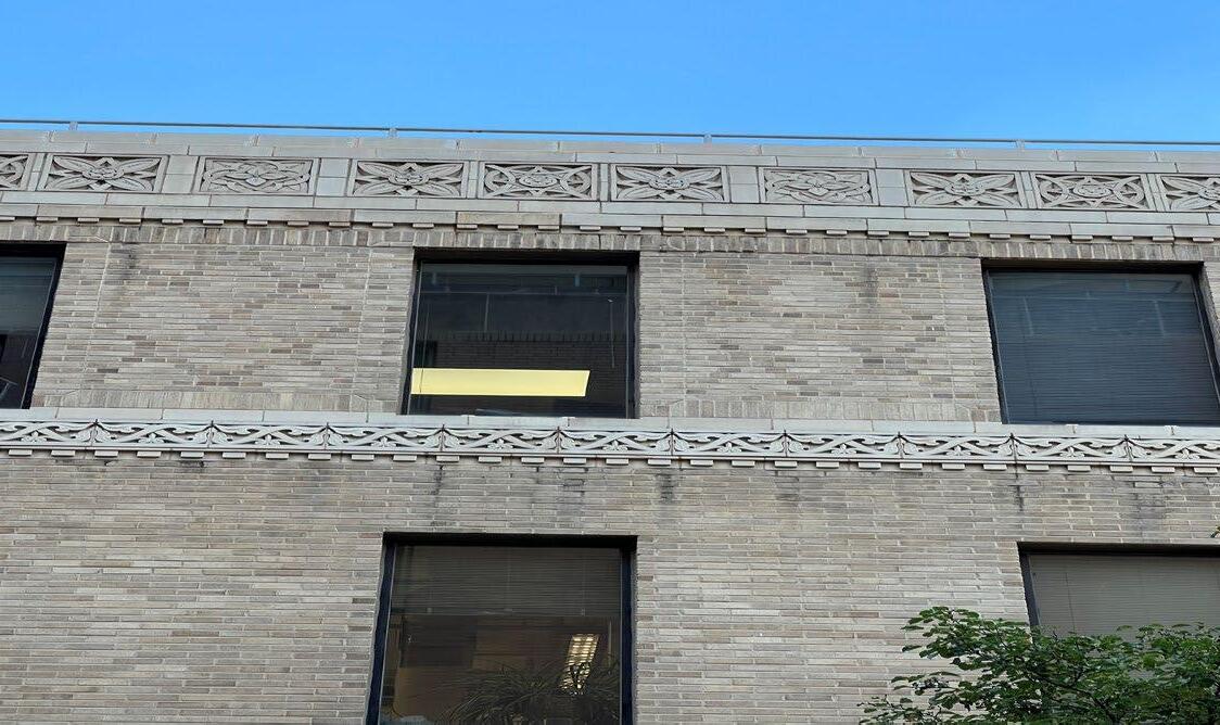
There is some discoloration on the limestone over time, this is an aesthetic issue. The limestone cornice (Approx. 48”), and horizontal limestone band just below the fourth floor windows are in need of re-pointing to seal any open joints. The brick coursing just below this band should also be re-pointed. Sealant may have been applied in some of these areas. The upper most coping stone that caps this wall should have the sealant joints removed, cleaned and new sealant applied throughout the building. Joints appear to be losing adhesion.
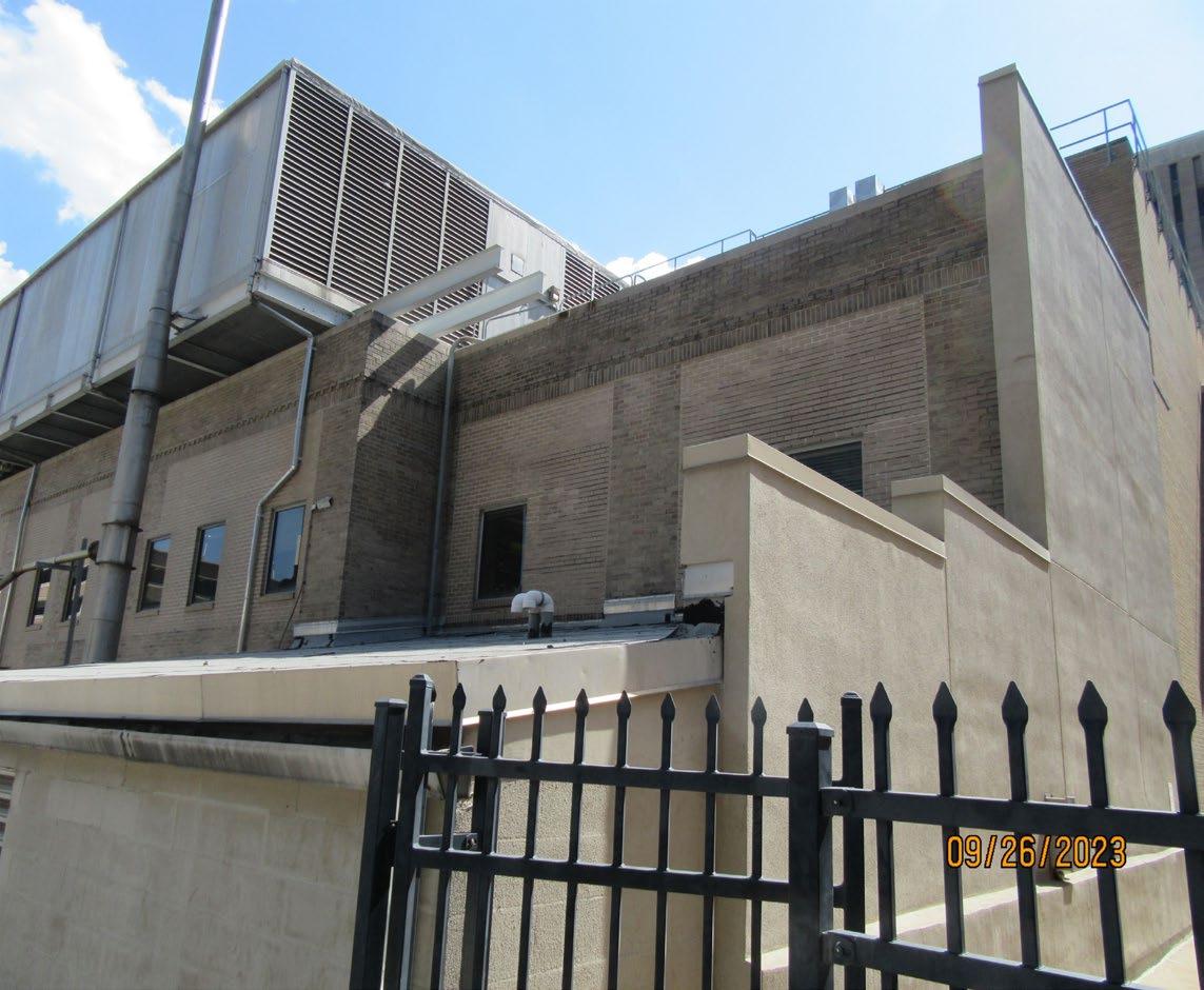
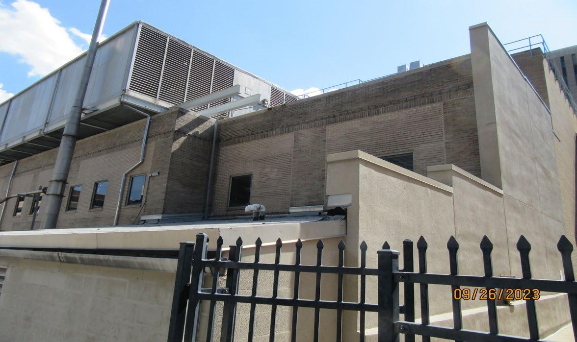
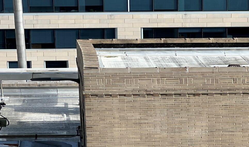
At the roof level several issues require attention. The brick clad penthouse on the roof of the 1927 building has open brick joints at the upper wall and the stone coping is showing signs of movement caused by water infiltration, these need to be addressed and the stones realigned and re-set to avoid further wall deterioration. The roof side of the masonry parapet walls require a closer inspection for brick joint condition. There is significant water ponding west of the penthouse and this condition has existed for a long period. All of the exterior wall coping stones are to have a closer inspection as joints are open on the exterior and roof sides. Coping stone joints should be removed and resealed.
Building #181 / Circa 1961 (Summary continued)
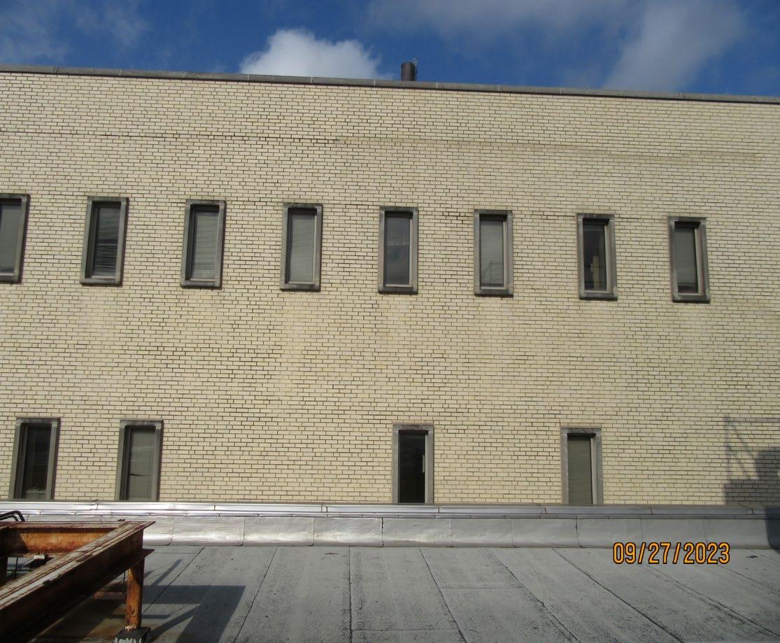
At the roof level of the 1961 addition the west facing wall that overlooks the 1927 roof has several locations of stepped cracking within the brick primarily at the windows. These are not significant structural issues but simply movement cracks that can be caused by water infiltration or material movement over time. Monitor cracks to see if there is additional movement over time. Some wall repairs apparent with the use of non-matching face brick. Several brick parapet walls on this roof should be inspected regularly as open joints are visible. One parapet wall has a significant length of counter flashing missing along its length. Ensure that any duct or piping penetrations thru brick walls have sealant applied to the top and sides of that openings.
The face brick on the 1961 building addition is in good condition. The punched windows on the east side have a limestone surround where some of the mortar joints are showing signs of openings but are not an immediate concern. The upper brick wall on the east side facing building East Building#070, approx. 48” down from the coping is a continuous horizontal open joint that appears to allow water infiltration into the wall as is evident by the discolored brick at the window head and jambs below. Any open joints on the east wall are to be re-pointed.
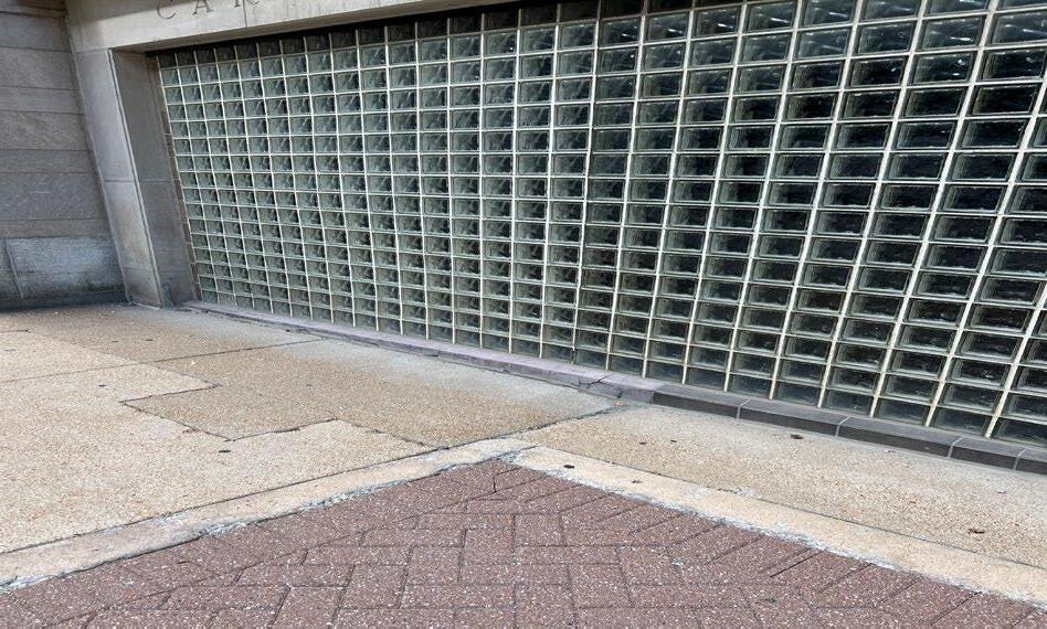
The glass block wall at the entrance is in fair condition but the head joint at the glass block wall that ties into the limestone above it has opened and needs new sealant to fill the gap. The base of the glass block wall has deteriorated and approx.50% of the tiled base has been replaced with a concrete mix that has significant cracking and requires replacement. Here again the ongoing exposure to salt will continue to erode these materials. If the slope of adjacent walks is not pitched away from the building walls this will continue to create water issues.
The glazed curtain wall glass is showing signs of surface discoloring and fading likely from its age as it is original to the 1961 build. Some of this appearance is due to the failure of the IGU (Insulated glass unit), spacer or seal and air leaking between glass units originally sealed at the factory. The exterior seals between units are at the end of their useful life (EUL). The top of the curtain wall assembly is protected with layers of lapped foil faced flashing used in roofing not as it is applied here.
The existing structural system consists of a concrete basement foundation with a mix of above ground structural framing systems. In the original building a concrete column + beam system supports concrete floor framing. The additions both consist of steel framing (primarily trusses) on steel columns with some load bearing masonry walls where they tie into the existing building. Based on discussions with WUSM, there is no future change of use anticipated and the current loading capacity should be sufficient.
None
The floor to floor of the building varies from 12’-0” (Basement to Ground and Level 01); to 12’-10”, 11’-5 1/2”, and 12’-6” (Level 01 to Level 04). The ceiling height in the building is varied in some locations due to elevation changes, but is predominantly 7’-8” to 8’-0” in the corridors and 8’-0” in the programmed spaces with ACT. In spaces with exposed concrete deck it varies from 9’-2” on the ground floor to 11’-2” on L2, and 11’-1” on L3. The exterior grade changes around the building, as well with the North side slop;sloping from just above the ground floor level to the West down to just above the Basement Level to the East. The south elevation slopes down to the East along Scott Avenue to create an interior first floor layout that has a variety of finish floor elevations and requires stairs to enter at the original 1927 entrance. The 1961 addition is level with the exterior pavement and could meet ADA or current code requirements for accessibilities if the door requires less than 5 pounds to operate or is equipped with an ADA Auto Operator. Additional commentary on the interior layout can be found in the accessibility section of this report.
The interior finishes primarily consist of new LVT in the public corridors, older VCT in the labs, and Carpet/ Carpet tile in the offices and conference rooms, and ceramic tile in the restrooms. The walls are either painted drywall or plaster/ brick and the ceilings are a combination of painted gypsum, hung acoustic ceiling tiles, or exposed concrete structure above that has been painted.
The basement currently consists of MEPFP infrastructure along with a small locker area for staff. The Ground Floor includes the main entrance lobbies, offices, labs, support spaces, and public restrooms along with Electrical infrastructure room. Level 01contains labs, offices, support space, conferencing, and an accessible route connecting to the East Building. Level 02contains labs, offices, support space, conferencing, and an accessible route connecting to FLTC. Levels 03 & 04 contain labs, offices, support space, conferencing and public restrooms. The last major interior refresh was conducted recently with new LVT and paint throughout the public corridors.
Finish renewals have been added.
D - Interior Finishes & Layout
D2- Interior Finishes & Layout-Renewal Category
181-D2-01
Level 00 Basement 01
181-D2-02 Level 01 GroundFloor 02
181-D2-03 Level 02 FirstFloor 03
181-D2-04 Level 03 SecondFloor 04
181-D2-05 Level 04 ThirdFloor 05
181-D2-06 Level 05 FourthFloor 06
Replace VCT, Repaint Walls, Doors, Door Frames X
Repaint Walls, Doors, Door Frames + Carpet in Offices and Conference Rooms, and Vestibule W.O.M. Replace VCT and ACT in Labs X
Repaint Walls, Doors, Door Frames + Carpet in Offices and Conference Rooms, Replace VCT and ACT in Labs X
Repaint Walls, Doors, Door Frames + Carpet in Offices and Conference Rooms, Replace VCT and ACT in Labs X
Repaint Walls, Doors, Door Frames + Carpet in Offices and Conference Rooms, Replace VCT and ACT in Labs X
Repaint Walls, Doors, Door Frames + Carpet in Offices and Conference Rooms, Replace VCT and ACT in Labs X
The plumbing piping systems are largely believed to be from the late 1980’s and/or early 1990’s. However, it is believed that the under slab waste lines were not fully replaced in these renovations, and are likely from the 1960’s. The incoming cold water is via the 8” combinations service, which splits to 8” fire protection and 4” domestic water services. The domestic hot water is made at the nearby power plant and piped to Biotech. There are RO/DI water system skids on the Ground floor level (room G033), along with a water softening system. The building has lab air, lab gas, and lab vacuum services piped though out the building, all originating from the lower level mechanical room B008. There is a main building 4” reduced pressure backflow preventor, and many other small local backflow preventors spread throughout the building.
Most of the above ground piping is cast iron and believed to have been installed in the major renovations of the late 1980s/early 1990s. There have historically been issues with splitting waste piping in the building, and recent efforts have replaced small portions as required. Typically, cast iron piping should be expected to have a 40-50 year lifespan. However, according to WUSM facilities personnel, this has not been the experience in this building, which has been experiencing corrosion failures. Additionally, there have been issues with pinholes in domestic hot water piping, which could be attributed to domestic water quality and piping age. Due to the above-mentioned issues, allowances should be planned to continually replace portions of piping, until all of the piping can be replaced in upcoming future renovations. During these renovations, plumbing piping infrastructure replacement should be the goal, rather than small renovations in a piecemeal fashion, which make it difficult to replace the main infrastructure.
Most of the below slab piping is believed to be original to the building. Buried cast iron has an expected service life of around 50 years. So, any piping from the 1960’s will have exceeded this expected service life.
The hot water originates at the adjacent power plant and is piped over to Biotech. No issues have been reported on the quality of the hot water provided, which is reported to be supplied at a pressure of 85 psi typically. The domestic hot water recirculating system is part of Power Plant systems, and the recirculation pump is not located in Biotech. It is believed that each floor has a main recirculation return line so that hot water is always on the floors ready for use. However, required distances from fixture to recirculated mains are probably not met in most of the lab suites. As renovations occur, the domestic hot water recirculating systems will need to be upgraded to provide recirculation at each fixture as required by codes. This will likely require new domestic hot water recirculation mains to be run through the building as renovations allow.
There is an acid dilution tank under the floor of an office on the ground floor (room G032). This system is reported as no longer being used, and this should be demolished, removed, and infilled when able to do so.
There is an 8” combination water service. As mentioned above, the incoming city water splits to serves the 4” domestic water, and 8” fire protection service. Domestic water pressure has not been reported as having any issues.
Biotech is equipped with a pure water system located on the ground floor in room G033, which consists of the RO, DI, and water softener equipment as described below:
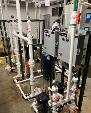
The deionized water system skid appears to be relatively new and in good condition.
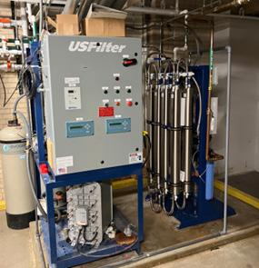
The RO water system also appears to be relatively new and in good condition.
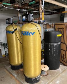
This water softener system also appears to be in good condition and shall only require regular maintenance and upkeep.
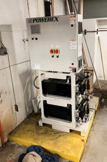
Lab Air
A central lab air compressor is located in the main mechanical room B008. This has a duplex compressor, and 5 HP motors providing 30.4 SCFM of compressed air to the building. This piece of equipment was installed around 2019 and is relatively new and in good condition. However, both pumps and motors have already required replacement. In addition to on-going regular service and maintenance, expect frequent motor/pump replacement going forward. There are 1.5” piping risers, which are piped to each lab suite.
Lab
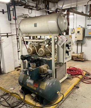
A central lab air compressor is located in the main mechanical room B008. It consists of duplex compressors, with 10 HP motors providing vacuum air service to the building. This piece of equipment was installed around 2006. Both pumps required replacement on two different occasions over the last seven years. In addition to on-going regular service and maintenance, expect frequent pump replacement going forward. There are 1.5” piping risers which serve vacuum to all the lab suites in the building.
Lab Gas
Natural gas is piped to all the labs via 1.5” piping risers. No issues reported or observed with the gas piping. The main incoming gas line recently was equipped with a seismic gas valve.
The building has a new main 4” reduced pressure backflow preventor on the domestic line which was serviced recently. Additionally, there are 20 to 30+ small local backflow preventors throughout the building serving equipment needs and individual labs for non potable water needs. Many of these are domestic water back up for cold room condensers, which are normally cooled by a dedicated loop condenser cooling loop. There will be recurring maintenance required with all these backflow preventors. They should also be tested annually. This building would be a good fit for a centralized non-potable water loop with a main backflow preventor in a main mechanical room, in say a future infrastructure upgrade effort. Due to the number of local backflow preventors, it should be expected to replace approximately 3 per year on a regular basis.
There are many emergency fixtures spread throughout Biotech, all of which require annual testing. Each floor has fixtures located in the corridors, and they are also located in each lab suite. These all appear to be from the 1990’s, although some have been replaced. Plan on replacing a few of the eye wash fixtures, emergency showers, and emergency stations each year until they have all been upgraded.
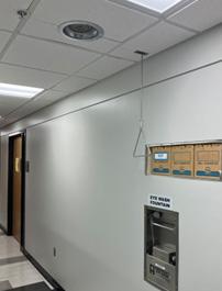
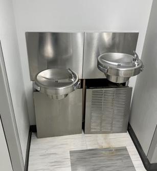
Each floor has electric water coolers located in the corridors. These are old, antiquated, and reported to be failing. Most of them have open service covers as shown in the photo below. It is reported that parts are difficult to get and are no longer available. They do appear to be past their expected service life and the recommendation is to start planning for their replacement.
Sewage Ejector Pump
The basement fixtures and floor drains are too low to gravity drain to the main sewage line (the ground floor and up are all gravity drained), and are as such, ejected using an ejector pump which is located in the B008 mechanical room. The reported pattern has been replacing the motor every 2 years on this pump, mostly due to foreign matter binding the motor up, such as mop strings and other items getting into the pump blades.
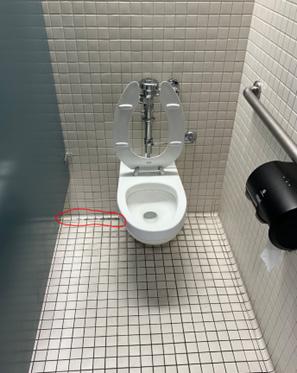
All water closets are wall hung, and most have some give once downward pressure is applied. This results in a bad contact seal at the wax ring, and as a result many (if not all) of the water closets leak down the wall behind the water closet, as seen by the water signs observed at each unit. The wax rings may all need to be replaced to prevent this from continuing.
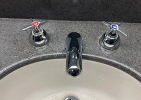
Many of the faucets in the public restrooms are showing signs of scale, but most are still working properly. Due to age, a replacement plan should be put together for the near future. A few are leaking at the countertops, but no serious water damage was observed.
Figure 12: Typical public restroom faucet. Most in decent condition, however, some are scaled up and leaking during use.
E - Plumbing
181-E-01 Domestic hot water 01 Correcting pin-hole leaks in supply piping X
181-E-02 Water Closets 02 All water closets are wall hung and gaskets are leaking. Replace all gaskets. X
181-E-03 Fixtures 03 Several instances of leaking faucet handles in restrooms. Replace faucets as required. x
181-E-04 Electric Water Coolers 04 Replace Electric Water Coolers throughout X
181-E-05 Above Grade Waste Piping 05
Sanitary piping above ground is cast iron( splitting @ top). Replace all waste piping in future reno. X
181-E-06 Sanitary Piping Below Grade 06 Sanitary Pipe Below Grade believed to be cast iron. Replace all of this as renovations allow. X
181-E-07 Hot water Recirculation 07
Domestic hot water/ recirc system (originates from Power Plant). Replace all domestic HW return piping in individual spaces as renovations occur to meet code lengths for un-recirculated piping lengths to fixtures. X
181-E-08 G033 08 Replace 3/4" leaking condensate line from glass washer above. X
181-E-09 B008 09 Replace Sewage Sump Pump motor every 2-3 years. X
181-E-10 B008 10 Lab Air compressor, Replace pump/motor assembly every 3 years. X
181-E-11 B008 11 Lab Vacuum Skid, Replacing pump/motor assembly every 3 years. X
181-E-12 Building Wide 12 Replacing (3) 3/4" backflow preventors annually X
181-E-13 Building Wide 13 Replace (2) emergency shower station annually, or as renovations allow. X
Biotech is cooled by chilled water from the campus loop. It is an “Import Only” building which controls the flow of chilled water via a control valve on a 10” chilled water line. There are two (2) main chilled water pumps that circulate the chilled water to the loads, which mainly consist of the two large air handling units. There is also a dedicated Cold Room Condenser loop that uses house chilled water to cool all the condensers. The piping is largely expected to be from the 1990’s and appears to be in good shape overall.
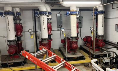
The main pumps are about 30 years old with an expected service life of 40 years. They are equally sized at 2400 GPM, 40 HP each, and are modulated using VFDs. Because the speed (flow) is controlled using the VFD’s, the existing triple duty valve on the discharge is just causing unnecessary pressure drop and energy usage. A potential energy saver could be considered, by removing this and replacing it with a check valve and service valve.
Additionally, recommend upgrading chilled water pump sequencing to include Out of Service Flag, and Fail to Run Alarm
13: Biotech chilled water circulating pumps
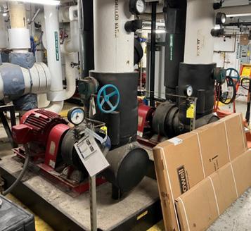
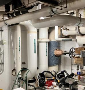
Figure 14: HVAC piping service entrance in B008. Includes 4” pumped steam condensate return, 10” chilled water supply and return., and 10” 50 psi steam.
The other loop off the chilled water system provides cooling to the condensers for all the cold room units (approximately 12). This loop was installed in 2012 originally. It is a 2” separate sub loop off the chilled water. Most of the cold room condensers have domestic water back up with several RPBP’s being located in remote locations.
The circulating pump for this loop is a 30 GPM, 90 ft, 5HP pump on a VFD. There are filter units which keep the water clean, prolonging the life of the condensers. This loop was observed to be in good condition with no preventative maintenance scope identified.
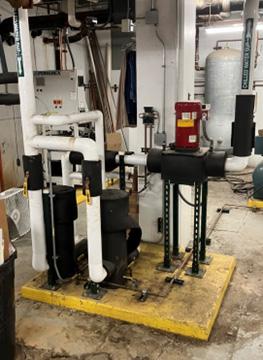
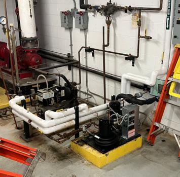
A 10” medium pressure steam line serves the building. 50psi steam is drawn from the campus system and is reduced down to 12psi at the main PRV station. Downstream of the main PRV, a 2” line serves sterilizers, while a 6” line serves the two steam-to-water shell and tube heating water heat exchangers. The steam condensate is all returned back to the condensate receiver unit, which pumps the condensate back to the source via a 4” pumped condensate return line. All of the piping and equipment appears to be from the late 1980’s or early 1990’s.
17: Steam-to-water shell and tube heat exchangers make heating water.
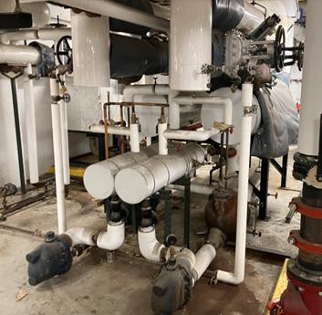
The main pressure reducing station has required maintenance in the recent past due to valve “chattering”. Due to the age, recommend replacement of these valves in the near future.
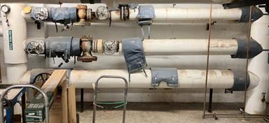
There are many steam traps throughout the building. Many need maintenance work, as they are leaking steam past. Particularly observed at some of the sterilizer/autoclave condensate lines, which are dumping steam to the rooms due to either leaking traps, or the need for a vented flash tank system. Plan on a recurring maintenance effort keeping up with the steam traps.
There is one main condensate receiver located in the LL mech room. It has a duplex pumping system, which pumps condensate back to the campus system. This unit is at least 30+ years old and has past expected service life. Plan on replacing this in the near future.
There is a leaking steam condensate line from one of the glass washers that needs replacement. The line is in the G033 room and drops down into the B008 mechanical room, where the leak is occurring.
Biotech is heated via a pumped heating water system that distributes heat throughout the building. The system is a primary-secondary system with a separate sub glycol preheat loop for the AHU’s. The heating water is generated by shell and tube, steam to water heat exchangers, using campus steam. The heating water loop temperature setpoint is reset throughout the year in the 125-170F range. All of the head end equipment is located in the B008 equipment room.
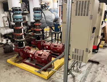
There are a total of 6 pumps on the heating water system:
1. 2 Primary pumps, 864 GPM, 15 HP (constant volume).
a. These units are about 30 years old with an expected service life of 40. Plan on replacing in approximately 10 years.
b. Recommend putting on VFD’s and removing the triple duty valves.
2. 2 Secondary Pumps, 864 GPM, 25 HP (constant volume)
a. These units are about 30 years old with an expected service life of 40. Plan on replacing in approximately 10 years.
3. 2 Steam-to-water shell and tube HXs
a. These units are about 30 years old with an expected service life of 40-50years. Plan on replacing in approximately 10-20 years.
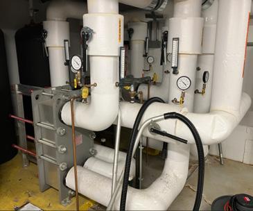
A pre-heating glycol loop is a separate sub loop of the main heating water system and provides heat at the AHU preheat coils. The AHU’s have very high percentage outdoor air, and the glycol loops help to ensure the coils don’t freeze up. The temperature of this loop is reported as being reset in the 130-140F range. Heat is taken from the heating water loop and added to the glycol loop via two plate and frame heat exchangers located in B008. There are two Tertiary Pumps, 510 GPM, 15 HP, which are also on VFD’s. All of this equipment is relatively new (2012), and no issues have been reported or observed. There is no recommended scope with this loop.
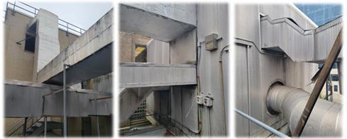
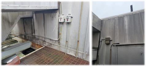
Two main air handling units (appears as one as they share a common piping vestibule), located on the lower roof of the two story building, provide all of the ventilation and cooling to the Biotech Building. The units are Air Enterprise units and, the exact age is not known, however they appear to be part of the 1990’s renovations. Both units had major controls upgrade in 2012, and both are generally in very good shape considering their age. The casings are all aluminum construction, which is in theory corrosion free. There are some signs of weathering of the AHUs, especially at caulking, gasketing etc. Additionally, the units have decent amount of dirt on the outside and could be used a good cleaning. The anticipated life span of a custom aluminum AHU is around 40 years. The casings are not going to last forever, and there are some reasons for concern here as the age is estimated at 1992. In 10 years from now some casing issues may need addressing. The roofing membrane on top of the AHUs was recently replaced and should be adequate for at least 10-15 years.
Both AHUs are situated on elevated steel structures, a few feet above the roof. The supporting steel needs to be scraped and painted to ensure they last as long as the AHUs will. This will be recurring every 10 years.
The units serve exterior ductwork, which runs across the roof to the building. There are some ductwork cladding issues, and this ductwork will need periodic treatment to ensure the insulation integrity and vapor barrier is kept intact. It appears one of the duct connections at unit needs some attention. A conservative plan would be to potentially reclad the exterior ductwork in the next 10 years.
Below is a caption of the two air handling units, showing the componentry.
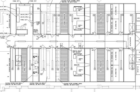
These units are generally in good condition and expected to last at least another 10 years reliably with only regular maintenance and those items identified above.
With all the laboratory spaces in Biotech, there is a lot of exhaust airflow loads. The current systems consist of many individual exhaust fans (approximately 54) on the roof, and most are past their expected service life, with a few exceptions. Most of these fans are belt driven vent set utility fans and require frequent maintenance to keep running due to the sheer number of belts and bearings. This is especially challenging due to the restricted access to the roof due to the radioactive nature of the research in this building. There are ongoing discussions about centralizing the exhaust systems in this building, which would be a good solution to solve the unreliability of the many older individual exhaust fans.
In the meantime, consider a recurring annual allowance for the 54 fans, until a possible consolidation project can be undertaken.
There are (2) two newer strobic fans that serve Radiology on the 4th floor. These fans will need to either be incorporated into the new central system or replaced as part of that upgrade project if required by that design.
All of the terminal units in the building (other than the 4th floor), were installed in the late 1980’s and/or early 1990’s with retrofit’s done in 2012 as part of the controls upgrade project that was undertaken. These units are all past their expected service life of approximately 30 years, which should be considered as individual renovations provide an opportunity to replace them with new units.
A more recent renovation of the 4th floor installed Phoenix valves for the Radiology department air systems: These should be expected to last 10-2o more years.
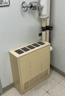
There are some cabinet unit heaters in the stairwells, which are well past service life and should be replaced.
There are two separate split DX systems serving the main electrical room on the ground floor. These units can both be expected to require replacement in the next 10 years.
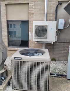
Controls
A major controls upgrade took place in 2012, in which the HVAC controls were fully upgraded, and all pneumatics were removed. The chilled water plant is on the JCI Metasys system. The remaining portion of the building is on the Schneider controls.
Existing T.A.C. I/A controllers are obsolete, and Schneider Electric will be discontinuing the production of these controllers in the next 2-3 years. Some older Barber Coleman 8000 controls will need to be upgraded to newer Schneider controllers.
F - HVAC
Scheider Control System with new JCI Metasys Control system
There are adequate egress paths, stair & door widths meet code, and quantity of access points within the building indicate no additional exits are required. In stairwells, exiting paths, lighting and signage appear up to code.
The building has an automatic sprinkler system as well as addressable life safety devices installed. It appears that the egress doors are rated doors + hardware. In stairwells, there seems to be proper ratings.
Life safety power is distributed from the standby diesel generator through transfer switch G1. Transfer switch G1 is 100A and distributes to panel GE1 and subfed to each floor with a 60/80 amp feeders – BE1, 1E1, 2E1, etc. Some non-life safety branch circuiting loads were identified on the panel schedule of life safety panels. All loads connected to the life safety distribution equipment need to be classified as emergency by article 700 of the National Electrical Code.
Emergency egress lighting and exit signs were observed. It is recommended an egress lighting study be performed to verify the appropriate lighting levels are met at the egress pathway.
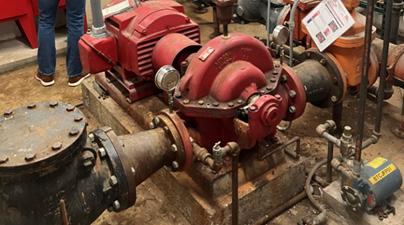
The fire pump, jockey pump and associated controls appear to be in good working condition. Feeder to the fire pump was observed as a conduit and wire feed. Feeder serving the fire pump shall be 2-hr rated, MI cable, 2 hour rated MC, or encased in concrete or a 2hr rated enclosure.
The fire alarm system consists of a Notifier voice evacuation panel. The panel did not have any active alerts at the time of inspection. Device layout appears to be appropriate for the building type and appeared to meet ADA notification requirements.
The building is fully sprinklered via an automatic wet sprinkler system. An 8” city water connection and a fire pump is located in the lower level B006 room. Each stairwell has either a standpipe or combination standpipe. There is also a Pre-action system in the main electrical room on the first floor of G013. It appears as though the fire protection system is approximately 30 years old, and the piping is believed to be late ‘80’s while some componentry being from the ‘90’s.
Main Fire pump (1994?)
The main building fire pump is an Aurora 750 GPM, 60 HP. It serves the sprinkler system and the standpipes. The controller was replaced approximately 5 years ago.
Jockey Pump
The jockey pump controller is antiquated, and parts are hard to obtain. Due to its age, the recommendation is to replace both.
Service
There is an 8” size service line coming from the city water with double check backflow prevention.
Standpipes
The two main stairwells are equipped with 6” automatic combination standpipes, which have hose connections and sprinkler zone valves at each floor. There is believed to be two zones per floor.
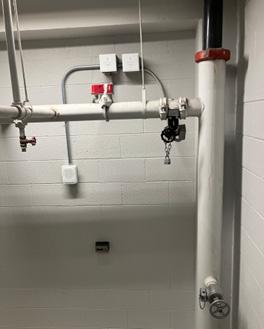
It is believed that the sprinkler system was installed in the late 1980’s and/or early 1990’s. It was noted that all of the sprinkler piping mains are schedule 10 black iron steel. The current WUSM standard is to replace the existing schedule 10 piping with schedule 40 piping. The threaded branch piping is black iron schedule 40.
Pre-action
There is a pre-action system in the main electrical room located on the lowest level (room G013). The piping is also subjected to accelerated corrosion due to the wetting and then filling with air that occurs as part of testing this pre-action system. The WUSM standard is to replace the schedule 10 piping with schedule 40 piping and install a new nitrogen generator to protect the piping from this cyclical corrosion sequence.
G - Fire/Life Safety / Fire Protection
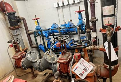
The building is served by 4160V feeds from the campus distribution. Four substations and other major distribution equipment reside in the main electrical room. The 208/120 volt distribution is comprised of an Eaton 2000 amp, 500kVA, double ended substation, USS-1 & USS-2 split down the aisle with a 2000 amp tie feed. In general, the substation serves a secondary distribution level consisting of two distribution panels on each floor GLD1, GLD2, 1LD1, 1LD2,…4LD1, etc. In addition to the normal power feeds to transfer switches G1 (Life Safety) and G2 (Lab Optional).The secondary distribution panels serve the general lab panels throughout the building.
The ground/bonding wires on the ground bar located in the main electrical room was observed to be ferrous material and did not contain a grounding bushings. Grounding bushings will need to be installed to maintain a viable ground path.
The 480/277 volt distribution is comprised of a 1600 amp, 750kVA, double ended General Electric double ended substation, USS-3 & USS-4, split down the aisle with a 1600 amp tie. In general, this substation provides power to the mechanical systems serving the building, including the fire pump. The 480 volt substation also serves as the normal feed to transfer switches G3 and G4.
The emergency power system consists of a 350kW Cummins diesel emergency generator with 500 gallon tank. Emergency power is distributed at 480/277 volt to transfer switches G3 & G4 and stepped down to 208/120 volt to serve transfer switches G1 & G2. Emergency (life safety) loads are connected to transfer switch G1. A mixture of optional standby and life safety loads were observed to be connected to the emergency branch.
All distribution in the building appears to be original, manufactured by General Electric with the exception of USS-1/USS-2 manufactured by Eaton and of modern vintage. For the most part, gear appears to be well maintained. Consideration should be given to the aging infrastructure in regards to expected useful life by IEEE Gold Book. A water leak was observed above panels BL1 & BE1 in the chiller room. Rust is forming on both panels and the bottom of distribution panel BP1 where the water is pooling. Each floor contains one electrical room housing the main distribution components and general panels for circulation areas. The space is shared by IT infrastructure. The majority of panels within the electrical rooms do not have the proper dedicated electrical space headroom above. Duct trunk lines and other utilities route through the space across the top of the panels.
Lighting systems consist of linear fluorescent and CFL fixtures that have been retrofitted with LEDs. Controls are standard toggle style. Energy saving occupancy/vacancy sensors should be installed to control fixture run time and reduce overall energy.
H - Electrical
181-H-01
181-H-02
181-H-03
181-H-04
181-H-05
Replace/Refurbish power panels and switchboards exposed to water in main mechanical room
Full checkout and review of ageing infrastructure to ensure operational efficacy. Replace aging infrastructure as renovations occur in the facility. Gear original to the building are 30+ years old. Life expectancy of Breakers 20yr, Panelboards 30yr, Switchboards 40yr, and Transformers 30yr.
Relocate panels under duct and other utilities. Panels should have clearance "dedicated electrical space" 6ft above panel or to structure (all electrical rooms)
Grounding/bonding installed without grounding bushing in main electrical room. Grounding bushings shall be installed on all ferrous conduit.
Redistribute emergency loads with Emergency, Legally Required, and Optional branches
2 passenger elevators were observed to service all 4 levels in the original 1928 building. Both of these elevators are slated for replacement in 2024. 1 freight elevator was observed in good working order with well maintained finishes and provides service all 5 levels in addition to the lower level basement mechanical space along the East end of the building.
None
The building appears to lack true MDF and IDF spaces for telecom and low voltage distribution. Telecom is distributed to racks located within the electrical rooms of each floor. Proper telecom spaces will need to be developed to distribute fiber and cat cabling and meet campus standards.
The 1961 addition entry is level with the exterior pavement however, the sloped pavement from the sidewalk is too steep for ADA. This could be improved by adding a handrail to make the entry ADA compliant as long as the entry door requires less than 5 pounds to operate or is equipped with an ADA Auto Operator. The building is connected to FLTC and East through accessible corridor links which both have clearly marked accessible routes from street level, and all of the floors are accessible by elevator. Where there is no defined accessible route to the Main Accessible Building Entry from any of the existing ADA parking , there are through the adjacent buildings.
The main accessible building entrance is at grade and has access to on street parking from an existing curb ramp at the sidewalk. The existing exterior entry doors are not equipped with accessible hardware or power-operated door opener; nor does the secondary set of entry doors from the Vestibule into the main Lobby but they do not meet the Maneuvering Clearances for Doors in Series from current Accessibility Legislation. It is recommended that a power-operated door opener be added to the secondary interior set of doors and be wired to open in tandem with the exterior power-operated door in the future if the entry storefront is replaced.
Current accessibility legislation requires that any building over two stories in height and currently serving the professional office of a health care provider is required to provide wheelchair access to all floors within the building. The current elevators are sized adequately for wheelchair access, and contain accessible call controls and a hands-free phone.
Existing Egress stair handrails and guardrails do meet code requirements with updates from the 1990’s.
Current accessibility legislation outlines Maneuvering Clearances at Manual Swinging Doors, Doorways without Doors, Recessed Doors and Doors in Series. Most of the interior doors do meet these current maneuvering clearances.
Current accessibility legislations outline guidelines for operable parts as they relate to doors, handsets should not require tight grasping, pinching, or twisting of the wrist; and doors should not require more than 5 pounds of force to operate. Most all of the interior doors are currently equipped with Levers that do meet these requirements.
The existing Lab and casework does meet current accessibility standards, but could be easily modified if needed.
Not all Sinks located at lab casework meet the accessibility standards but could be brought up to current accessibility standards when casework is altered. Sinks at public restrooms do meet current accessibility standards with the height and should also have pipe wrap installed if the sink meets all other accessible requirements, full replacement if not.
All restrooms in the building are not compliant with current accessibility guidelines, however alterations of the existing restrooms to bring them up to current standards may not be feasible based off available adjacent space required for expansion. It is noted that Level 2 does have access to FLTC to the West and that building has accessible restroom that meets current standards. The building did go through ADA upgrades in the early 1990’s to meet the accessibility code at that time.
All water coolers meet current accessibility standards.
Interior Signage
Most Signage existing within the building is currently ADA compliant. It is recommended that all signage should be upgraded to current ADA standards regarding size/graphics, height, braille and location requirements with any new major renovations.
None
It is recommended that a risk assessment and abatement be done prior to any future renovation work or demolition.
It is our understanding that buildings constructed before 1978 typically have lead based paint. Because the buildings last major renovation was in 1985, it is recommended that a risk assessment or inspection for possible lead-based paint hazards is recommended prior to any future renovation.
**It has been observed that the building’s plumbing system may contain asbestos, which is covered in the plumbing section of this report.
The overall building has been reviewed and categorized by “use type” categories that include Public Spaces & Circulation, Office, Office Support, Exam Rooms, Lab Space, Medical Support, Restrooms, and Building Systems.
Each space is measured against individual criteria to rank it from a Class A to Class C space in respect to overall quality and condition. The total number of points for each category varies as some spaces will hold more value from a renewal prioritization perspective, i.e. exam rooms vs. office support space.
Each criterion under the use type gets a score of A (100% of possible points), B (67% of possible points) or C (33% of possible points). The totals are then added together and divided by total possible points to give each use type category an A, B or C score. In the building summary, the use type categories are averaged together to give the building an overall score.
The final A-C grading scale for the overall building is determined by the following:
• A = 85-100% | Recommendation: No work to minimal upgrades necessary ($)
• B = 60-84% | Recommendation: Medium upgrades necessary ($$)
• C = 0-59% | Recommendation: Large and expansive upgrades necessary ($$$+)
Note: Breakdown of Spaces based on OSIS report from WUSM and updated during this reporting based on observations.
Basement
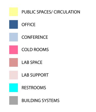
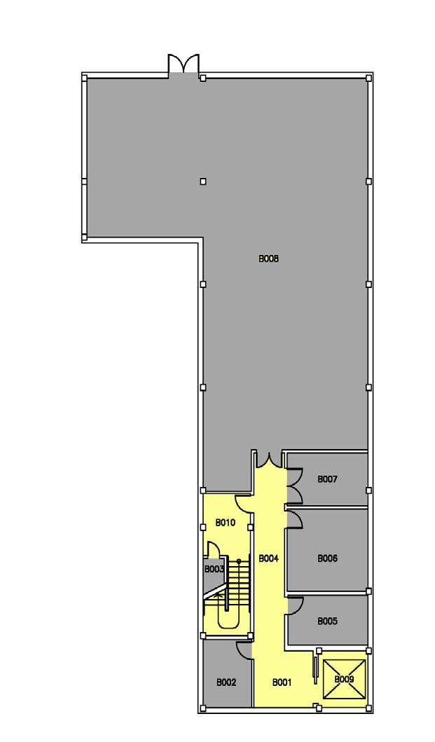
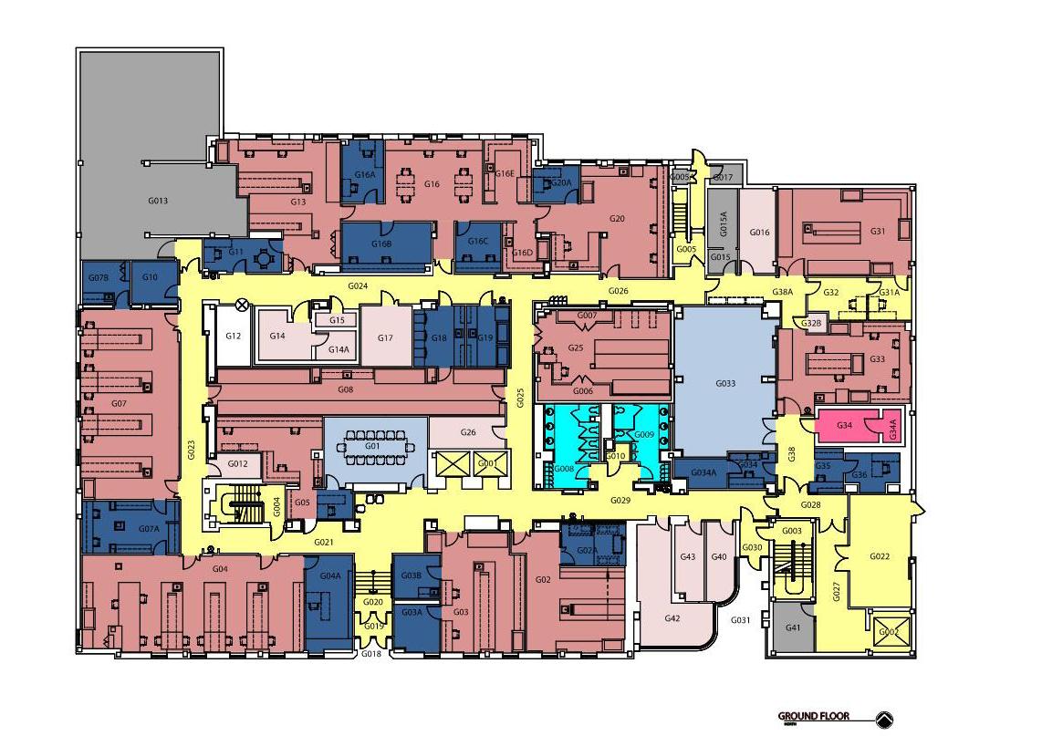
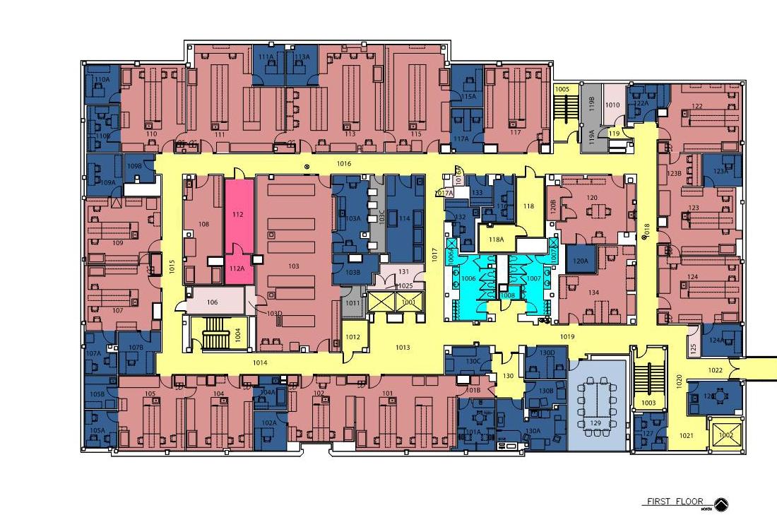

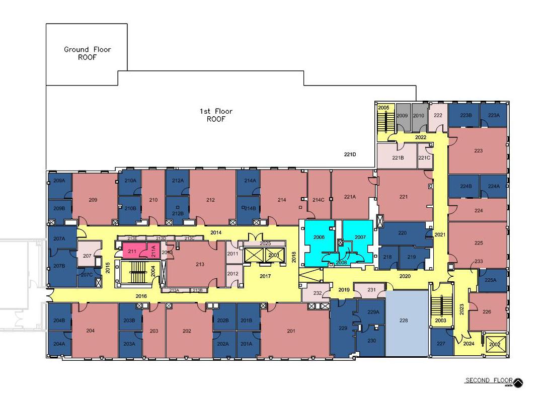
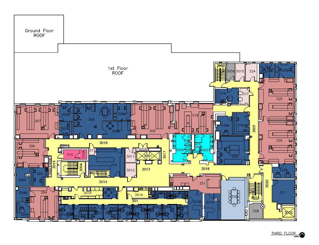


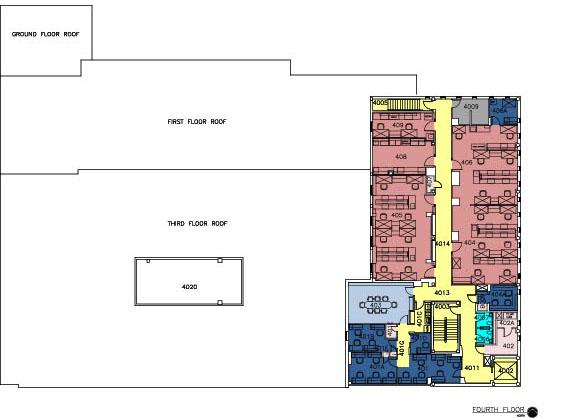
*Notes: Accessibility Descriptor criteria is defined as:
• A = Building is in line with current Accessibility Standards or requires minimal upgrades
• B = Building is moderately in line with current Accessibility Standards, but requires significant upgrades
• C = Building is minimally in line with current Accessibility Standards and requires extensive building upgrades
Building 181 Cost Report R2.1 Biotechnology Center

Prepared: June 12, 2024 by: Cost Report 1 of 27
Introduction
Moss Construction Cost Management Incorporated (“MossCost”), as part of the LJC design team, has been tasked to provide third party/independent cost modeling and estimates for the Washington University School of Medicine 2024 Facility Condition Assessment (“FCA”). This report contains estimates of the likely probable cost of correcting such existing deficiencies as were identified during the site inspection by LJC team members, together with estimates of future renewal costs.
This report should be read in conjunction with the document “Standard Notes / Guide to the Cost Report” 1 which provides guidance on understanding the cost report and includes pricing notes, exclusions and assumptions.
Basis of Estimate(s)
Draft FCA spreadsheet and inspection report of 21 & 22 November 2023
Comments/query responses of 28 November 2023
Additional items per LJC email of 21 December 2023
Revised/updated cost summaries received 20, 21 & 22 November 2023, 25 January & 15 March 2024
LJC Navvis Ivion capture (360 degree site walkthrough)
Archival drawings received from WUSM
Estimate Issue
This issue: R2.1 with minor revision to graphics
Previous issues: R2.0 with renewal items & updated format, 12 May 2024
R1.0 30 November 2023
Initial Draft 29 November 2023
Summary of Costs2 3
1 Current edition dated 14 February 2024
2 For further summaries and supporting data, refer to “Corrective Cost Details” section later in this report.
3 Escalated cost based upon 10 year lookahead

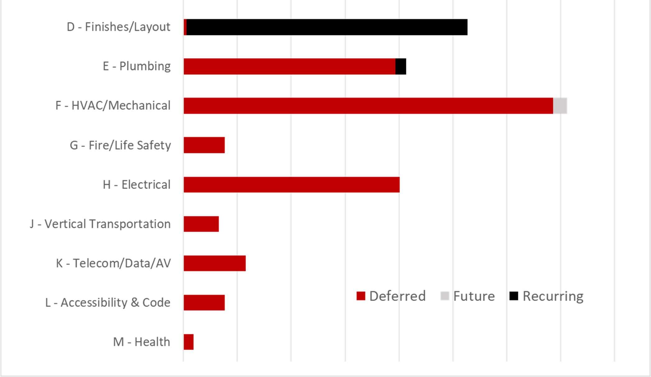
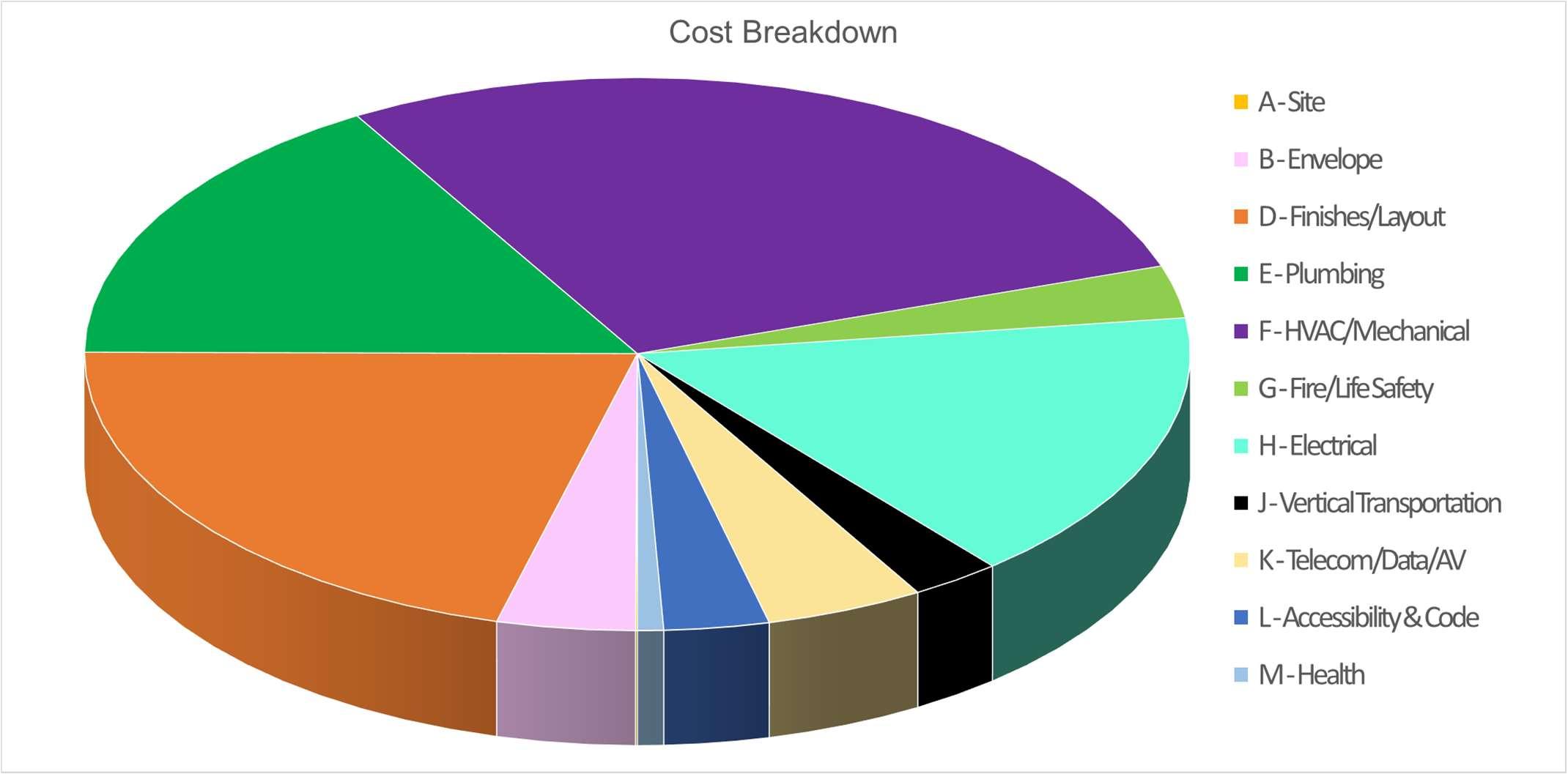
For this asset the following items potentially overlap:
(1) ceiling and wall access for MEP modifications and corrections – if plumbing items E01, E05 & E07 are performed as a combined project, a cost reduction of $1,135,616 is possible
(2) phasing allowances – if plumbing items E01, E05 & E07 are performed as a combined project, a potential cost reduction of $342,553 is possible
(3) electrical/telecom room reconfiguration – if item 181-K-01 is implemented, dependent upon timing items 181-F-16 and 181-H-03 would not be necessary ($266,378)
(4) bathroom upgrades – if item 181-L-01is implemented, dependent upon timing items 181-E-02 & 03 would not be required ($20,872)
A total adjustment of $1,765,419 is made in the calculation of the facility indices to allow for these non-unique costs.
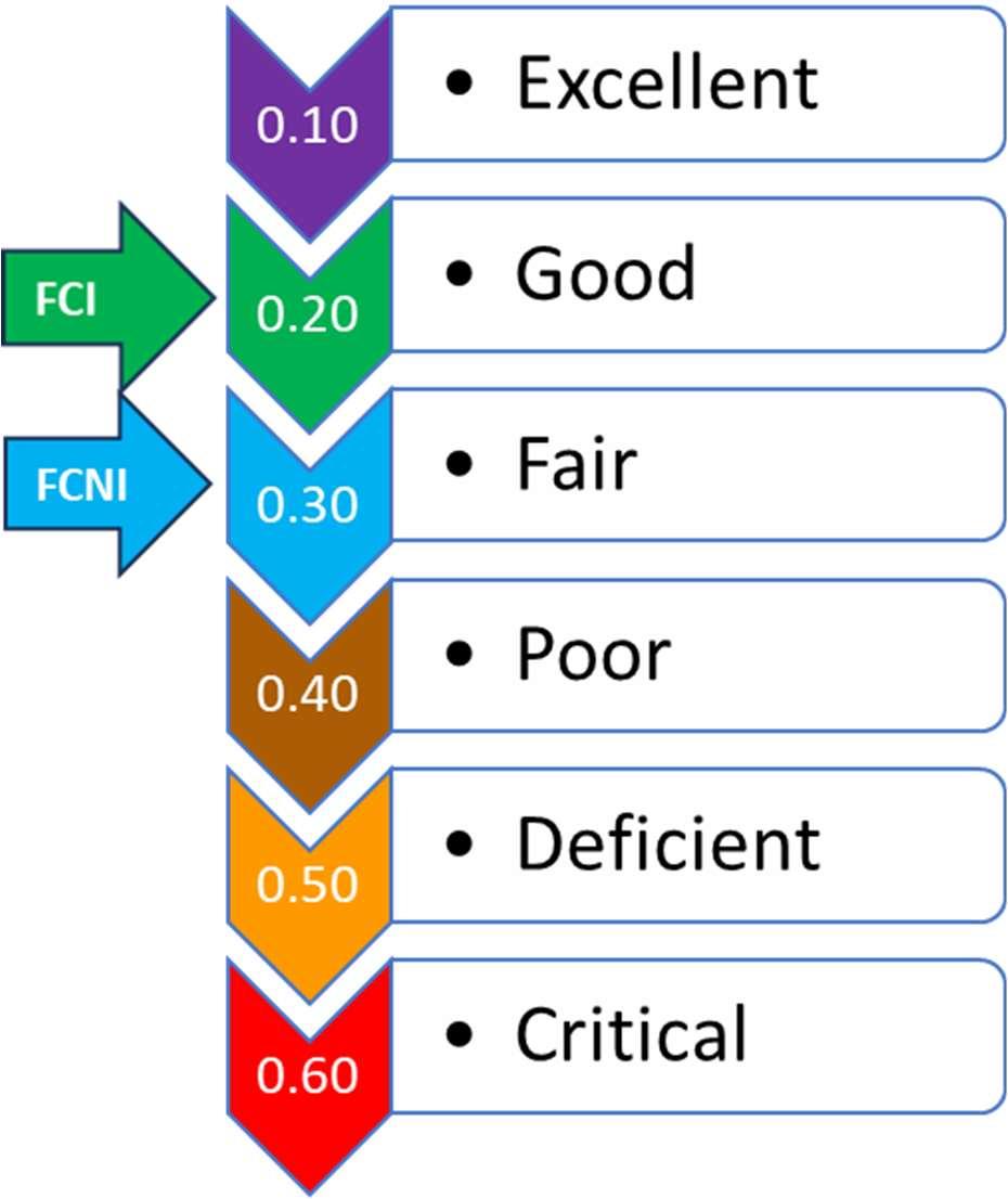
Based upon the cost estimates attached, the preliminary indices are as follows, indicating a building in good condition and will remain so with appropriate investment over the next 10 years.
Deferred Costs
Non Recurring (Deferred) Costs $ 19,254,230
Non-Unique Costs $ (1,765,419)
A. Unique Cost Corrections $ 17,488,812 Future Costs
Non Recurring (Future) Costs $ 258,541
Non-Unique Costs $ -
Recurring Costs (10 Year Look Ahead) $ 5,599,593
B. Future Costs $ 5,858,134 CRV
Replacement Cost per WUSM $ 66,586,603 Design Fees & Program Markups Included
C. Current Replacement Value $ 66,586,603
Condition
Purpose and use of estimate: The intent of any estimate contained in the cost reports is to reflect fair market value for the correction of deficiencies noted. It is not a prediction of lowest, or any, bid. It is an opinion of probable cost intended as a tool for cost control for budgeting purposes. The estimator can not and does not guarantee that bids, proposals or actual construction costs will not vary from any estimate or study.
Scope of work: The line items included in the estimate represent the estimators understanding of the scope of work as communicated by the documents identified in the basis of estimate. Any apparent discrepancies and/or significant differences in understanding should be brought to the estimators’ attention as soon as possible so that interpretation of scope can be clarified.
3 -

D2 - Finishes & Layout - Renewal 94,067GSF42.60$4,007,572.99$5,145,724
$770,482


Row
350 painting - steel dunnage at AHU enclosure
351 painting - steel dunnage, add cost for hazardous
environment 181-F-12 - Exterior Ductwork
D30 HVAC
356 ductwork, roof, remove cladding, allowance
357 ductwork, roof, replacement cladding, add cost forModerate3,000.0SF $7.86$23,579$30,276 hazardous working
358 ductwork, roof, replacement cladding, allowance
$30.89$92,656$118,970 181-F-14 - Consolidate Roof Exhaust
D30 HVAC
363 exhaust fan, rooftop, consolidate exhaust, add forHigh 1.0LS$177,857.14$177,857$228,369 hazardous working
364 exhaust fan, rooftop, consolidate exhaust, add forHigh 4.0PHASE$44,464.29$177,857$228,369 phasing
365 exhaust fan, rooftop, consolidate exhaust, allowanceHigh
F20 Selective Demolition
C30 Interior Finishes 373 ACT ceiling, allow for R&R for HVAC access
$11.29$49,694$63,807
485
486
487
480V/800A
492


Row
#Item Description
C30 Interior Finishes
495 ACT ceiling, selective, allow for R&R for electrical workModerate30,000.0SF
D50 Electrical Systems
498 reroute/update electrical feeders, selective
499 electrical distribution, existing panel modificationsLow
500 electrical distribution, substation (new in 2011?) Low
501 electrical distribution, upgrade post-1994 equipment -Moderate
allow 50%
502 electrical distribution, upgrade pre-1994 equipmentModerate
503 electrical distribution, upgrades, phasing allowanceModerate
F20 Selective Demolition
electrical demolitions, distribution equipment & feedersHigh
181-H-03 - Relocate Panels for Headroom
D50 Electrical Systems
511 electrical rooms, reconfigure, allowance @ 1f (rmHigh
1010)
512 electrical rooms, reconfigure, allowance @ 2f (rmHigh
2010)
513 electrical rooms, reconfigure, allowance @ 3f (rmHigh
3010)
514 electrical rooms, reconfigure, allowance @ 4f (rm 4009High
Z90 Project Cost Estimate
electrical rooms, reconfigure, may not be practicalHigh
- Grounding
Project Cost Estimate 531
K

D20 Plumbing


181-F-02 - Secondary CHW Pumps
D30 HVAC
817 replace CHW pumps, 2y, 40 HP - FUTURE (2033)Moderate 2.0EA$30,505.20$61,010$78,337
- Replace Heat Exchanger
D30 HVAC
822 Replce steam-water HX, FUTURE> 10 years Moderate
- Primary Pumps
D30 HVAC
827 replace HHW pumps, 1y, 15 HP - FUTURE (2033)Moderate
- Secondary Pumps
D30 HVAC
832 replace HHW pumps, 2y, 15 HP - FUTURE (2033)Moderate 2.0EA$19,833.77$39,668$50,933 HVAC/Mechanical Total
$2.14$201,356$258,541 Recurring
A - Site
- Horizontal Sealant Joints
G20 Site Improvements
842 replace sealant joint, @ building/sidewalk , every 5-8Low
years


1
2
3
4
Notes:
(1) Current costs are 1Q24 dollars.
(2) Escalated costs reflect a 3% annual rate.
(3) Non-recurring required renewal costs are averaged over a 5-year period unless specific replacement dates are known.
(4) Non-recurring recommended renewal costs are averaged over a 10-year period unless specific replacement dates are known.
(5) Recurring costs are assigned based upon anticipated life cycle of building systems and components.
(6) Some minor rounding issues may be apparent when compared to estimate detail.
$35,000,000
$30,000,000
$25,000,000
$15,000,000 $20,000,000
$10,000,000
$5,000,000
B181’s envelope and interior spaces are in good shape with items noted that would be considered as typical maintenance cost. Required envelope items include minor roof repairs and caulking along with recommended maintenance item should allow Biotech to continue to serve the core campus for decades to come.
The majority of the items noted in the MEPFP category relate as much to the buildings age and its use as a laboratory building. The majority of the required MEPFP items are plumbing related with some minor HVAC and Fire Protection items noted as well. There are additional major Mecahnical, Plumbing, and Electrical items notd as recommendations that should take place within the next 10 years. The replacment of the elevators along with some ADA items and health abatement are also noted.
Prepared: February 14, 2024 by:

MossConstructionCostManagementIncorporated(“MossCost”),aspartoftheLJCdesignteam,hasbeen taskedtoprovidethirdparty/independentcostmodelingandestimatesfortheWashingtonUniversitySchoolof Medicine2023FacilityConditionAssessment(“FCA”).Thesenotesareintendedasaguideforunderstanding thecostreportsproducedforeachbuilding/asset.
Theintentofthecostreportistosupportstrategicandbudgetaryplanningforagivenasset.Itachievesthisby providingkeyperformancemetrics(inthiscase,thefacilitiesindices)thatcanbeusedtoquicklyascertainthe stateofagivenbuildingandenablecrosscampuscomparisonofthebuildingstock.
Thereportsummarizesthecostdatarelatingtotheanticipatedcostofrepairorreplacementofthevarious buildingcomponentsidentifiedbytheinspectionteamasbeingdefectiveandrequiringcorrection,orsoonto requirecorrection.
Thecostreportcomprises:
1) Summaryofcostsbytype&priority
2) Descriptionofnon-unique/overlappingcosts,ifany
3) ThecalculatedFacilityConditionIndices
4) Correctivecostdetails
5) Summaryofdeficiencybypriorityclassification
6) 10Yearlookahead
Thecostreportcontainsestimatesofthelikelyprobablecostofcorrectingsuchdeficienciesaswereidentified duringthesiteinspection.CostestimatespreparedaspartoftheFCAeffortarepreliminaryopinionsand subjecttovariationwhentheworkisplanned,designed,andexecuted.Each itemistypicallytreatedasa standalonetask.Thiscanleadtodisproportionatelyhighercoststhanifitemswerebundledintoprojects(for exampleanentirefloorrefurbishment)whichwouldrealizeeconomiesofscale.
Thecostassessmentspreadsheetistheprimarybasisfordeterminingthescopeandextentofagivencorrection, andcategorizationintonon-recurringandrecurringcosts.Followingcompletionofthebuildingwalkthrough and360-degreescan,draftreportsgeneratedbytheinspectionteamareusedasthebasisfordeveloping estimatesofthelikelyprobablecostofcorrectingexistingandanticipatedfuturedeficiencies.Reference materialincludingarchivaldrawingsandequipmentreportsareusedtofurtherinformtheseestimates. Followingreviewbydiscipline,thescopeofeachlineitemisconfirmed,andcostsrefinedandcategorizedas deferredorfutureanda10yearlookaheadproduced.
ConstructionCost: Estimatedprobableconstructioncostofthosecomponentsnormallyincludedwithinthe hardconstructionbudget,togetherwiththeappropriateestimatingriskfactor.
CostTypes: Costsfallintotwomaincategories:Non-recurringandRecurring.Furtherclassificationincludes deferred,future,andnon-unique.
CurrentReplacementValue(CRV): TheCRVofafacilityistheestimatedprojectcosttoreplaceafacility withoneofsimilarfunction,appearance,buildingsystems,buildingmaterials,architecturalandsitedetail includingdesignfeesandprojectmanagementcosts.Currentreplacementvaluesforthisstudywereprovidedper WUSM(6November2023).
Escalation:Thechangeinexpectedcostovertime,forwhichprovisioncanbemadeasacontingency allowanceinestimation.Estimateswithinthecostreportexcludesuchallowance.Thelookaheadaddsa3% annualescalationtofuturecosts.
FacilityConditionIndex(FCI): Aratioofthecostofrequiredcorrectivemeasurestothecurrent replacement valueforafacility.Itisderivedbydividingdeferredrenewalcostsbythereplacementvalue.
FacilityNeedsIndex(FCNI):Aratioofthesum ofallnonrecurringandrecurringcoststothereplacement valueofafacility.
Lookahead:Ascheduleofthefuturecorrectivecosts(bothnon-recurringandrecurring)overadefinedperiod. Thelookaheadperiodforthisstudyis10years.Timingisbasedupontheexpectedendoflifeofbuilding componentswhereknownand/orthecyclicalrenewalofsystems.Fornon-recurringdeferredcosts,item priorityclassificationisusedtoinformschedule.Typically,priority1isassumedtobeexpendedinthecurrent year,priority2inyears1-5andpriority3inyears1-10.Non-criticalitems(priority4)areplacedinyear10.
Non-RecurringCosts: Correctivecoststhatarenormallyone-timeonlywithintheanticipatedlifeofthe buildingasset.Suchcostsareassociatedwithbringinganassetbacktoasatisfactoryconditionandincludeall deferredrepairstogetherwithnecessarylifesafetyandothercodecorrections.Theymaybefurtherclassifiedas deferred(pastdue)orfuture(comingdueduringthe1ookaheadperiod). Example; replacing a non-functional or failing supply fan would be classified as a deferred cost. Replacing the entire AHU at its expected end of life 8 years from now would be a future cost.
Non-UniqueCosts:Correctivecoststhatduplicateorotherwiseoverlapworkcoveredbyotherestimates.Costs insuchcaseareprovidedforinformationpurposesshouldOwnerelecttonotperformagivencorrective measure,orwherethetimingoftheworkisnotoptimal.Forexample,acorrectioncallsforthereplacementof sprinklerpiping.Aseparateitemcallsforcommunicationcablingtobeupdated.Bothitemsrequireceiling accessandallowancesareincludedinthecostsforthis.Ideally,thecorrectionworkwouldbeperformedasa combinedprojectallowingtheoptimizationofceilingremovalandreplacementandavoidingcostduplication.
ProjectCost: Estimatedconstructioncostsplusdesignfeeandprojectmanagementallowance.
PriorityClass:Deficienciesareclassifiedintermsofurgencyintooneoffourrenewalcategories; Immediate, Necessary,RecommendedandNon-Criticalappliedasfollows:
1 ImmediateRenewal Immediatecorrectionrequiredtoeither(a)correctasafetyhazard(b)prevent accelerateddeteriorationand/or(c)returntonormaloperation.
2 Required(Necessary)Renewal Short-tomid-termactionrequiredtopreventfurtherdeteriorationortocorrectnonlife-threateningcodeissues(e.g.accessibility).
3 RecommendedRenewal Suggestedbutnotessentialimprovementstothebuildingtoincreaseefficiencyand/or usability.
4 Non-CriticalRenewal Noactionrequiredunlessuseoroccupancychanges,ortocomplywithcodeas grandfatherclausesexpire(forinstance,duetoexpansionorremodeling).
RecurringCosts:Manybuildingsystemsandcomponentshaveausefullifeshorterthanthatofthe building/structureitself. Recurring costsrepresent thenormalrepairandreplacementcostofsuchbuilding systemsandcomponentsastheyreachtheendoftheirusefullife.Forthepurposesofthisstudy,suchrecurring costswereidentifiedfora10yearlookaheadonly.
RenewalCosts:Renewalcostsarethosecostsassociatedwiththecyclicalrefreshingoftheinteriorfinishesof aspace,regardlessofwhethersuchitemshavebeenclassifiedasadefectbytheinspectionteam.Where refreshingthefinishesisoverduethesearecategorizedasdeferredcosts,otherwisetheyareshownasrecurring futurecosts.Thefollowingtableshowstherenewalcycleofvariousfinishesasappliedtothisstudy.
TheFCIandFCNIareusefulmetricsthatcanbeusedtoquicklyascertainthestateofagivenbuildingand, whenappliedconsistently,enablecrosscampuscomparisonofthebuildingstock.Theindicescanbeappliedto anysubsetofanassetportfolioandusedtocomparewithcompetingfacilities.
Inreviewingtheindices,itisimportanttonotethatthehighertheindexvalue,themoredeficientabuildingor groupofbuildingsis.AsFCIincreases,theassetswillexperience:
•Increasedriskofcomponentfailure
•Increasedfacilitymaintenanceandoperatingcosts
•Greaternegativeimpactstooccupantsandusers
Thefollowingchartisaguidetointerpretingdifferentindexvaluesasappliedtoabuildingasawhole.Tiers aresomewhatsubjectiveandarbitrary,andwerecommendthatthesebereviewedincontextofthepresent studyanduser(WUSM)specifictablebedeveloped.

Whatdoestheindexsayaboutyourbuildngcondition?
0.10•ExcellentCondition(likenew)
0.20•GoodCondition(wellmaintained)
0.30•FairCondition(normalrenovationrequired)
0.40•PoorCondition(significantrenovationrequired)
0.50•Deficient(extensiverenovationrequired)
0.60•Critical(totalrenovation/replacementindicated)
Allestimatedcostsareincurrentdollars(pertheeffectivedateofeachreport)1 . Laborandequipmentratesarelocationspecificwithproductivitybasedonnationalaverages. Materialscostsarebaseduponnationalaveragesadjustedforlocation. Competitivebidprocurementassumed.
Adequatebidcoveragefromgeneralcontractorsandsubcontractorsassumed. Allworkisperformedduringnormalworkinghours. Estimatesincludesallowancesforthefollowing,asappropriate: Accesstoitemstoberepaired/replaced.
1 Anescalationallowanceisincludedonthe10yearlookahead,atarateof3%.
Disturbanceorremovalofadjacentelements
Temporarysupports
Servicedisconnections&reconnections
Restorationofelementsaffectedbythework
Difficultyofaccess
Safetyrequirements
Thefollowingmarkupsareincludedintheestimates:
1) EstimatingRiskfactor.Itemshaveariskratingasfollows:
a) Low:Requirementsareself-evident anduncomplicated.Riskofunforeseen conditionsislow;factorof 10%added.
b) Moderate:Extentofdeficiencymayextendsomewhatbeyondwhatcanreadilybeobserved. Unforeseenconditionsarelikelytobeencounteredbutnotexpectedtobeextensive;factorof20%.
c) High:Extentofdeficiencyandrequirementforcorrectionaredifficulttoascertainwithoutextensive investigation. Riskofunforeseenconditionsandunanticipatedworkishigh;factorof35%.
2) Constructioncostmarkupof30%isaddedtonetcoststocovergeneralcontractor’sstaging/general requirements/OH&P
3) Locationaladjustmentasappropriate
4) Designfees@7%
5) WUSMprojectadministrationandcontingency@20%
Inthecostreport,“ConstructionTotal”includesmarkups(1),(2)and(3).ProjectTotalincludesmarkups(1) through(5).Allothermarkupsareexcluded.
Correctivecostitemsareanestimateofprobableconstructioncostofthosecomponentsnormallyincluded withinthehardconstructionbudgetandlimitedtothoseitemsidentifiedbythesiteinspectionteams. Estimationofotherdisciplinesandprojectcosts,notlimitedtothefollowing,isexcluded.
Furnishings,appliances&movableequipment
Artwork
SupplycostofOwnerFurnished,ContractorInstalled(OFCI)items
Supply&InstallationcostofOwnerFurnished,OwnerInstalled(OFOI)items
Itemsmarked"FFE","NIC",“EXCL”orotherwisespecificallyexcludedwithintheestimatedetail
Systemdevelopmentchargesorutilitycompanysurcharges
Operational&indirectimpact/disruptioncosts
Escalation(exceptasallowanceincludedin10Yearlookahead)
Futuremarketconditionchanges
Routineandcontractmaintenance,annualinspections/certification
SwingSpace,temporaryhousingorparking
Premiums/allowancesforspecificprocurementmethods(e.g.8A/SDVOSB)
Space,functional,securityissuesrelatedtothecorrectivemeasure
Project“softcosts”exceptasstatedunder“Markups”
Consultingfeesexceptdesignfeesandsuchstudiesascalledoutinreport
Constructionadministrationcosts,and/orowner’srepresentativefees
Projectlevelcontingencies
Constructioncontingencies
LEEDapplication/certifyingfees,ifappropriate
Independenttesting,inspection,orthird-partycommissioningagents
Thelookaheadislimitedtothoseitemsidentifiedbythesiteinspectionteamsandexcludesupdatesof expendituresforecastbypriorFCAstudies2
Allworkwillbeperformedbyoutsidecontractors,competitivelyprocured.
Unlessexplicitlystatedotherwise,eachFCAitemisassumedtobeaself-containedpieceofwork,performed independentlyofothercorrections.
Whereaccessworkforbuildingservicesandrelatedsystemsrequiresdemolition,reinstatementand/or abatement,itisassumedthattheseeffortswillnotbecoordinated/optimized.Anyduplicationofeffortis, however,recognizedinthenon-unique/overlappingcostsummaryofeachreport.
Itmaybeunrealistictocutout,patch,andrepairpartofanassembly. Inthatcase,estimateincludesforfull replacement.
2 Perprojectdescription“whilethecurrentISESreportincludescostnarrativesoffuturecapitalexpendituresupto10years,forthepurposesof thisproject,theconsultantwillnotbeincludingupdatedre-occurringexpenditures.”
CostsarepresentedusingthefacilityconditionreportitemcodewithaUniformatlevel2breakdownperthe examplebelow.Deficiencieshavebeenprovisionallyallocatedapriorityclass,howeverwithintheclassitems arenotsortedbycriticality.
AssetID
B064 4511ForestParkRADOC
CostType 1 Non-Recurring(Deferred)
FCACategory/System A Site
FCA Item#
064-A-01A Mill&overlayparking
UniformatL2Code G10 SitePreparations
Cost/RiskFactor 1 Low

Standard Abbreviations
Atableofstandardabbreviationsusedintheestimatesisappended.
Disclaimer
Purposeanduseofestimate:Theintentofanyestimatecontainedinthecostreportsistoreflectfairmarket valueforthecorrectionofdeficienciesnoted.Itis notapredictionoflowest,orany,bid. Itisanopinionof probablecostintendedasatoolforbudgetingpurposes. Theestimatorcannotanddoesnotguaranteethatbids, proposalsoractualconstructioncostswillnotvaryfromanyestimateorstudy.
Scope: NodesignsolutionsarepresentedaspartoftheFCA. Theestimatorhasthereforeusedhisbest judgementtodeviseaworkingsolutionforthedeficienciesnoted. Estimatorisnot,however,adesigner, architect, engineerorcodeofficial.
BDFT Board Feet
BGSF Building Gross Square Feet
CF Cubic Foot
CFM Cubic Feet per Minute
CRV Current Replacement Value
CSF 100 SF
CY Cubic Yard
DAY Workday
DGSF Departmental Gross Square Feet
LVS Leaves
NA Not Applicable
NASF Net Assignable Square Feet
NB Important note3
NIC Not in Contract
NSF Net Square Feet
OFCI
OFOI
Owner Furnished Contractor Installed
Owner Furnished &Installed
OPG Opening
EA Each PR Pair
EOL End of Life
ETR Existing To Remain
EXCL Excluded
FCA Facility Condition Assessment
FCI Facility Condition Index
FFE Furnishings, Fixture & Equipment
PTS Points
R&R Remove & Replace
RM Room
RMS Rooms
RSF Renovated Square Feet
SET Group of Items
FLR Floor SF Square Feet
FLRS Floors
SFFA Square Foot Surface Area
FXT Fixture SQ Square (100SF)
GSF Gross Square Feet
STN Station
HR Hour STOP Elevator Stop
INCL Included in another item
LF Linear Foot
LFR Linear Foot (of) Riser
LOCN Location
LOT Group of Items
LS Lump Sum
3 FromtheLatin “NotaBene”meaningnotewell.
SY Square Yard
TBD To Be Determined
TON 12,000 BTUH- Heating& Cooling
TON Short Ton (2,000 pounds) - Steelwork
VLF Vertical Linear Feet
YRS Years