Title: Brief advice on some corrective measures to be used before and after crossing the ground or rock due to induced breakdown during the excavation phase of a tunnel in an urban area using the traditional NATM System or using a TBM-EPB
by Luigi Franco, LAMANNA (*) 1. Introduction Below I would like to illustrate, through a simple schematic representation, the procedure to be adopted to cross an area in which there is a "fault", and at the same time try to reduce the consequent damage, following a possible "collapse" of the soil / rock, during the excavation phase of a tunnel for the metropolitan and / or railway network, using a TBM-EPB Mechanized Cutter. The methodological techniques that are usually adopted are very varied, however our only goal, through this memory, is only to suggest, based on our experience, the types of consumables to be used in such situations, for engineering applied in underground and highly urbanized environments, and therefore requires a preventive study, which must be increasingly technologically advanced, to determine the real impact of the construction of these
All photos illustred are copied from the WEB
underground lines on the buildings present on the surface.
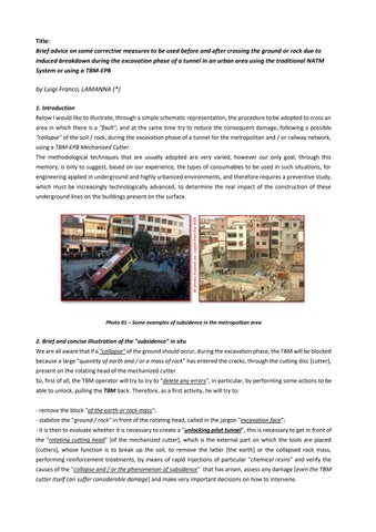
Photo 01 – Some examples of subsidence in the metropolitan area
2. Brief and concise illustration of the "subsidence" in situ We are all aware that if a "collapse" of the ground should occur, during the excavation phase, the TBM will be blocked because a large "quantity of earth and / or a mass of rock" has entered the cracks, through the cutting disc [cutter], present on the rotating head of the mechanized cutter So, first of all, the TBM operator will try to try to "delete any errors", in particular, by performing some actions to be able to unlock, pulling the TBM back. Therefore, as a first activity, he will try to: - remove the block "of the earth or rock mass"; - stabilize the "ground / rock" in front of the rotating head, called in the jargon "excavation face"; - it is then to evaluate whether it is necessary to create a "unlocking pilot tunnel", this is necessary to get in front of the "rotating cutting head" [of the mechanized cutter], which is the external part on which the tools are placed [cutters], whose function is to break up the soil, to remove the latter [the earth] or the collapsed rock mass, performing reinforcement treatments, by means of rapid injections of particular "chemical resins" and verify the causes of the "collapse and / or the phenomenon of subsidence" that has arisen, assess any damage [even the TBM cutter itself can suffer considerable damage] and make very important decisions on how to intervene.
Once all this has been done, which requires very long treatment times to eliminate the elastic component of the deformation, the TBM can be started again and immediately afterwards, the excavation can be continued. Thus described it seems very simple, but in reality we are faced with a truly complex geological event because, during the excavation phase with a TBM-EPB, and in a highly urbanized area, it is necessary to have preventive control, to respect fundamental constraints. In particular: 1. avoid damage to the infrastructures and buildings on the surface present in the urbanized area; 2. guarantee the safety of workers in all phases of work because the staff has to work in small spaces and many times, to unlock the TBM head, small charges must be detonated, creating the problem of manually removing the rock fragments; 3. check the normal increase in stresses in the temporary lining as a result of the decay of the soil resistance parameters, asymmetrical loads (due to geomorphology, in particular in the vicinity of another cavity), and soil heterogeneity; 4. avoid the triggering and re-mobilization of instability phenomena of the excavation side; 5. recover the most difficult part which is the plastic component through the injection of a stabilizing resin
All photos illustred are copied from the WEB
formulation.
Photo 02 – Example of the subsidence phenomenon outside the metropolitan area
I would like to point out that the construction of metropolitan tunnels in urban environments inevitably produces an alteration of the stress-strain state of the ground. The effect is felt at the level of the country / road level in a more sensitive way the more superficial the tunnels themselves are: the mechanized excavation and the ways in which this is carried out inevitably produce the development of subsidence that also spread over great distances and can sometimes have a catastrophic impact on the urban environment due to the presence of artefacts and infrastructures close to the excavations [v. buildings, bridges, roads, railway lines, etc.] and this particularly conditions the choice of the excavation technique, especially the one in which mechanized TBM-EPB cutters are used, or those with the traditional system [NATM Method] or even open pit [Cut and Cover], where all must prevent and minimize any subsidence phenomena that may occur on the surface.
I remind the technicians of the sector that many times the phenomenon of "subsidence", during the excavation phase, in particular using TBM-EPB, is caused by consolidation processes of clayey sediments due to a decrease in water content or due to external loads , given their particularity of presenting a high compressibility. However, the factors that most influence the movements induced by the excavation are due to the tension variations associated with the various construction phases, in the realization of deep excavations, which involve variations in the stress state, in the hydraulic boundary conditions and, above all, in the thrust conditions of the surrounding land that can give rise to appreciable displacements on the surface.
Extensione of the susubsidence
Longitudinal subsidence profile
Excavation face
All photos illustred are copied from the WEB
Transverse subsidence profile
Fig. 01 – Graphic representation of the subsidence basin in correspondence of a superficial tunnel. There subsidence curve varies according to the type of terrain encountered (coarse-grained soils K = 0.2-0.3 while fine-grained soils the value will be K = 0.6-0.7)
A significant proportion of the displacements produced by the construction of an excavation with the traditional [NATM Method] or open pit [Cut and Cover] system occurs already before the excavation in the phase of construction of the support works which, as for the subsequent construction phases, can be understood through the determination of the so-called "stress path". In fact, by ideally subjecting an element of soil to such stress paths, it is easy to demonstrate that subsequent inversions of the "stress paths" can be associated with important variations in the stiffness characteristics of the soils and consequently greater deformations induced in the surrounding volume. Therefore, the geotechnical and environmental problems connected to the construction of metropolitan or railway infrastructures, as well as the alteration of the stress equilibrium induced by the excavation, can induce subsidence of the ground strictly connected with a potential damage to the interference of the buildings [Building Condition Survey BCS and Building Risk Assessment BRA] and the civil structures existing on the surface, as they are all linked to the effects that the construction of deep excavations, and therefore involves, as on the physical environment that surrounds them, an interference with the underground services etc., but will be subject to an in-depth future memory. However, it should be noted that the construction of underground works, in particular tunnels or underground and railway stations, is always subject to certain constraints that greatly depend on the conditions of the place and the type of work to be built. It is in fact very important to remember that the construction of tunnels for metropolitan and railway transport requires, in addition to stabilizing the excavation, also the difficult control of the deformation during the entire life of the work, a requirement which can be met by means of a considerable limitation of the maximum pressures that are determined on the lining and on the concrete prefabricated segments, definitive in the long term, resulting in the limitation of the formation and / or failure of the lining. I would like to underline how well the designers of modern infrastructures are aware that the behavior, particularly that of the rock, whether pushing or swelling, is not uniform along the tunnel and that therefore the development of pressures in the long term can be extremely variable. I would like to point out that, when using the excavation technique using the traditional NATM Method system, a shotcrete coating, used without particular measures, is not suitable when one is in the presence of pushing or swelling soils and / or rocks. In these cases our main objective will be to limit the deformation of the ground and / or the rock by means of a temporary support, but it is often not sufficient to contain the deformation of the rock and is damaged or completely destroyed by subsidence.
All photos illustred are copied from the WEB
DIRECTION OF EXCAVATION
Fig. 02 – NATM Method – Possible ground movements induced by the construction of underground structures. The color photo illustrates control parameters of foundation buildings [Risk classification according to Rankin, 1988]
However, without using the appropriate precautions, the ground and / or the rock slowly "pushes" the already broken lining until a position of equilibrium is reached or the excavation collapses. Therefore, one of the appropriate countermeasures is to introduce yielding ribs together with anchors [a topic already addressed in a previous memoir]. 2.1 - Anchoring to the rock I would like to briefly illustrate the excavation of tunnels, with the traditional NATM method, which takes place according to the following phases, because I would like to underline once again what I describe at the bottom of the conclusion of this point 2.1): - excavation, carried out with hydraulic hammers operated by compressed air or gas, depending on the expected behavior of the soil; - removal of debris; - safety by laying a pre-coating with metal supporting structural elements (ribs) and subsequent application of reinforced Spritz-Beton (coating). In particular, the anchoring to the rock takes place through a structural element operating in traction, capable of transmitting forces to the ground. Functional parts of the anchor are: - the locking device and the distribution plate placed at the head of the bar; - the reinforcement consisting of steel or glass fiber bars or profiles; - mechanical expansion anchoring device, or as we want to underline later, by means of a particular formulation of silicate resin (organo-mineral and non-polluting), in the terminal section of the structural element in order to guarantee a perfect union between rock and bar .
All photos illustred are copied from the WEB
Photo 03 – From our experience of tests done in the laboratory using a climatic chamber we have I was able to verify that the steel bar did not suffer any corrosion and that the particular resin formulated silicatica has not undergone any degradation but is able to pass aging tests of more than 100 years (500 years)
In the recent past, not to mention even today, the fixing of the steel iron bar was done by injecting a cement mortar. I would like to underline that the resistance of the anchor depends on the resistance of the reinforcement, on the adhesion (which can be guaranteed over time only by the injection of the particular formulation of silicate resin) between rock and bar as well as on the nature of the ground. The silicate resin formulation that I suggest is a non-polluting product, does not catch fire, is not corrosive, penetrates cracks of the order of 0.005 inches and also blocks any water present in the subsoil. 3. Some hypotheses to solve the problems that are encountered The campaign of preventive geognostic investigations being studied aims to characterize the stratigraphy from a geological, geotechnical and environmental point of view by means of in situ tests along the route of the future underground or railway line. In recent decades, the new metropolitan lines and in particular the high-speed railway ones provide for the construction of tunnels, even of large diameter for the railway ones, and which develop in extremely variable rock masses, using mechanized TBM-type cutters, even in high convergence rock masses. But thanks to the technological progress in the field of cutting tools [cutters] and in the power / thrust of modern TBMs, it is now very rare that a rock formation can be considered economically “unmillable”. In fact, today the TBM has been developed to operate in adverse rocky conditions and in particular in the presence of high convergence rock masses and subsidence of the excavation face, even with large diameters [12-15 meters]. The ability of the TBM to operate in such adverse excavation conditions is an essential element in the case of large diameter tunnels and in the presence of complex geological formations. In fact, when digging in the presence of a water table, in addition to allowing dry machining, this [the TBM] is able to ensure the stability of the excavation face, through the control of neutral pressures. The apparently most advantageous stabilization technique results in a "catchment" of the aquifer which, however, entails inevitable resentments on the regime of the underground water table in the construction phase. Particularly interesting and innovative are the most modern techniques for limiting induced settlements for the protection of existing structures on the surface, through soil consolidation, carried out directly in the construction phase to compensate for induced resentments. 3.1 - Brief summary of the consolidation intervention in a fault area and in the presence of water flows Another of the most important aspects during the excavation phases by means of a TBM of a blind hole tunnel in a fault zone with water flows whose presence, many times, has not been identified by the boreholes. In addition to
causing discomfort in the work environment, these cause instability, especially in difficult terrain. It is therefore necessary to adopt particular measures, such as the immediate stop of the TBM, to make investigative holes to obtain information on the nature of the material and the extent of the fault zone, then proceed with a waterproofing and consolidation through injections of sub-holes horizontal radial pattern (nr. 8 ÷ 10 holes, inclined from 3° ÷ 12°), of one-component hydro-reactive polyurethane resin of the PU-8402-FOAM type (or a modified formulation called PU-8408-FOAM type) and then look for to stabilize the landslide front with the insertion and injection of a particular formulation of organo-mineral resin (foam) of the SILEX-330-FOAM type. The peculiarity of this new PU-8408-FOAM type product is that, during injection, if the resin comes into contact with water, it increases in volume, if it does not find water, it hardens without foaming and at the same time pushes the porous material in the innermost layers forming an impermeable and compact layer of variable thickness.
PROBE HOLES
INTERCEPTED EOLOGICAL ANOMALY
TBM-EPB
Fig 04 - Schematic representation of excavation near a fault. Interception of the fault. Unstable material: clay, sand, debris, ect.
Furthermore, the presence of several extended faults, and if there is a high tendency of the front to collapse, in addition to what has been previously described, it is necessary to create a protective umbrella for the consolidation of the front up to and beyond 3 meters by intervening on the healthy rock, injecting some product. of the SILEX-330FOAM type and if necessary another product of the SILEX-304-STONE type [non-expansive] which, thanks to its high fluidity, the latter resinous formulation is able to penetrate even through cracks of a few hundred microns in width In fact, the mixture of a resinous nature tends to follow the major cracks, where the pressure losses are less high, to the detriment of the minor cracks which remain open. To solve this, I suggest interrupting the injection for at least 5 minutes, waiting for the already injected product to catalyze and repeat the treatment until the rejection pressure is reached. APPROACH PHASE WITH RADIAL PERFORATION AND INJECTION
Injection of resin type PU-8402-PU
TBM-EPB
Fig. 05 - Schematic representation of the approach phase with radial perforation and injection (no. 8 holes) of resin type PU-8402-FOAM
3.1.1) - Some considerations on the injection of polyurethane foam of the "PU-8402-FOAM" type to block the water on the excavation face. The range of polyurethane formulations allows the structural consolidation of a large part of the soil, but the use of one or the other product must be evaluated on site based on the geomorphological characteristics found. As already mentioned, since most of the products are two-component, they must be injected by means of special pumps with a static mixer in the head. The component feed pipes, which are separated, can be several meters long, as long as the pump has sufficient pressure. Furthermore, as previously mentioned, the type of product "PU-8402-FOAM", being a single-component product that reacts only in the presence of water or moist soil, having a very long pot-life (even for several days, if stored at dry), there are no limits of use, subject to sufficient pumping pressure, to the length of the injection pipes. APPROACH PHASE WITH RADIAL PERFORATION AND INJECTION – 3-5 m
Injection of resin
TBM-EPB
type SILEX-330-FOAM
Fig. 06 - Schematic representation of the approach phase to 3-5 m. with radial perforation and injection (no. 12 holes) of resin type SILEX-330-FOAM
It should be borne in mind that many of the products mentioned above have been studied and formulated precisely for the control of water inflows in tunnels, mines and underground works in general. I repeat, the product type "PU8402-FOAM" is a polyurethane resin formulation designed specifically for the rapid blocking of water during excavation with TBM-EPB cutters. When the formulation comes into contact with water, a chemical reaction rapidly takes place which leads to the formation of a consolidating foam with closed cells, characterized by absolute impermeability and chemical stability. I specify that during practical applications on site, to allow the advancement of the TBM, even in difficult soils and with high water flows, the expansion factor is linked to the quantity of catalyst introduced since, the formulation type "PU-8402 - FOAM ", is a single-component product that reacts only in the presence of water; in the absence of water, it remains stable, in the form of a gel, even for several years, and consequently the blocking power of water is determined by the amount of water present and the pressure of the same and the quantity of catalyst introduced (from 1 ÷ 5%). The information described in this study experience led me to conclude that the consolidation and waterproofing injection interventions in an underground environment, especially in the vicinity of water sources intended for human consumption, require greater attention and knowledge in the choice of products to be injected. In fact, the problem of water outflows in tunnels and in underground works in general, must not be seen only as a cause of delay or increase in costs in the construction phase, but as a rehabilitation and prevention action in order to make our intervention compatible with environmental protection. 4 - Some hypotheses of preventive safety to avoid in situ subsidence The route of a tunnel considered that develops in an urbanized environment, the tunnel underpass, with reduced coverage of the underground line as well as the lithological nature of the subsoil, highlighted by means of a detailed cost-benefit analysis, it is necessary to decide the most suitable excavation method , as an alternative to the
traditional type, and therefore it is necessary to operate with preventive interventions to contain the excavation in order to limit subsidence on the surface.
TBM-EPB
Fig. 07 – Scheme of the stabilization and / or consolidation phase of the ground (bearing capacity), even in the presence of pressurized groundwater, before excavation with TBM along the path of the future tunnel by injection of resin from above. This type of intervention must be carried out under the control of the environmental impact. This type of treatment can be carried out when it is possible to intervene from above, as the tunnel is not very deep, within the metropolitan areas.
A method of treating the stability of the ground of the excavation face is that by means of injections of cement mixtures and / or resinous formulations which arises from the need to improve the characteristics of mechanical resistance and impermeability of porous soils or rock masses. The improvement can be obtained with various injection techniques which can be classified according to the level of inlet pressure and according to the type of mixtures used. In the construction of metropolitan and / or metropolitan tunnels in urban areas, in recent decades there has been a notable development, worldwide, on the use of the mechanized balanced pressure shield [TBMEPB Earth Pressure Balance Machine] and on the function of chemistry in the treatment of soils through a series of mixtures that produce the maintenance and stability of the soil of the excavation face. The mixes can be used in consolidating and / or waterproofing treatments [preventive and otherwise] to allow the excavation phase in conditions of maximum safety as well as reducing surface subsidence and soil permeability. 5- Conclusions The design and construction of a tunnel, as we have mentioned above in this brief memoir, is conditioned by multiple factors that can vary over time according to the evolution of the preliminary knowledge to the final stages, thus allowing, many times, to adapt the project to the geological-technical conditions that gradually meet. The convenience of carrying out consolidation interventions, to be defined according to the geological characteristics and also by the excavation methods, are the fundamental tool for maintaining the integrity of the core at the face and allowing the advancement of the cutter in an environment that has not already collapsed. Much has already been illustrated in various articles on the traditional NATM system. There is a wide range of publications both of a general nature and on specific experiences. While the purpose of this new article of mine is to draw attention to how some particular types of resinous formulations are participating in the rapid evolution in progress of the new ways of building new infrastructural tunnels and not with the use of TBMs. Current TBMs are proving to be able to overcome the exceptional events that may be encountered during excavation very well, in particular during the excavation of a deep and very high-coverage tunnel, where the forces of nature can generate unpredictable and extremely critical conditions and that, at the same time, these conditions can be faced and overcome by innovative methodologies and technologies, as demonstrated daily by the competence and dedication of many technicians in the sector.
The introduction of cement injections as a useful means for filling any voids on the back of a coating or for consolidating the soil or rock surrounding a cavity is now superseded by the use of new silicate-based resinous formulas (CFC-free and halogens) because these harden in a few minutes and also because the same resins can participate in supporting part of the load in a short time and be able to combine with the particular geological conditions that arise.
Fig. 08 – Examples of consolidation underthe roads and manufactured before digging a tunnel for underground
Furthermore, the choice between the different excavation systems is substantially dictated by the geotechnical and geomechanical characteristics of the soil and the cost / benefit ratio of the intervention. Remembering that construction times and costs cannot yet be predicted. But finally today the construction of the tunnels has finally been industrialized for any terrain and tension conditions because the excavation progress no longer depends on the ground but the terrain is modified in order to proceed as quickly as possible. In fact, the discussion of these topics, as I have always pointed out in my articles, can often seem trivial. Also to clarify that preliminary investigations are necessary, both in the design and construction phases, and that the application of injection procedures, the types and characteristics of the mixtures, as well as their methods, have become essential in the construction of a tunnel. However, my only purpose is to have, on the basis of the mutual knowledge and experience of the readers, through the effort to use a simple and respectful language made up of information exchange, which in this context has nothing to do with deep emotions or with vested interests, but to arrive all together, through observations, theories, through our cognitive abilities, also made by the different professional roles, of those who deal with this particular sector, without decentralizing ourselves from our reference information, we will not be able to understand some of our colleagues and therefore everything would be nothing more than a simple flawed information. But is not so. Because we need the insights needed for greater understanding, as well as pre-containment measures. However, the conflicting opinions that can emerge from all gallery experts, as has happened in the past, are being examined by the undersigned author.
(*) Luigi Franco, LAMANNA Independent Technical Consultant in the sector of Tunnelling, Mining and Underground Technology President of the Fondazione Internazionale di Centro Studi e Ricerche, ONG 132, via dei Serpenti, 00184 ROMA, Italy, U.E. Email: lamannaluigifranco1@gmail.com