Shutdown SIS
Previous Screen
Product: WHEEL LOADER
Model: 962K WHEEL LOADER T6A
Configuration: 962K Wheel Loader T6A00001-UP (MACHINE) POWERED BY C7.1 Engine
Disassembly and Assembly
950K and 962K Wheel Loaders Machine Systems
Piston Pump (Implement) - Assemble
SMCS - 5070-016-II; 5070-016; 5070-016-FD; 5084-016-QP; 5084-016
Assembly Procedure
Table 1
Required Tools
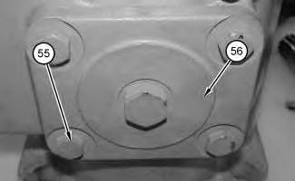
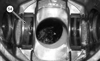
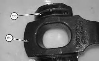 Illustration 2
g02722269
2. Install cover (56) and bolts (55) .
Illustration 3
g02722268
3. Install bearings (54) .
Illustration 2
g02722269
2. Install cover (56) and bolts (55) .
Illustration 3
g02722268
3. Install bearings (54) .
4. Install bearings (53) onto swashplate (52) .
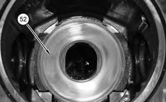
5. Install swashplate (52) .
6. Raise the temperature of bearing (51) .
7. Install retaining ring (50) and bearing (51) onto shaft assembly (49) .
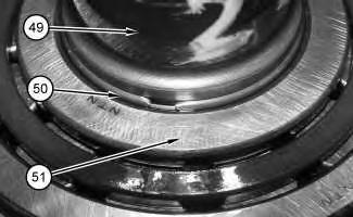 Illustration 4
g02722267
Illustration 5
g02722266
Illustration 6
g02722265
Illustration 4
g02722267
Illustration 5
g02722266
Illustration 6
g02722265
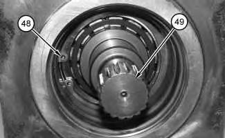
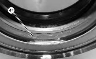
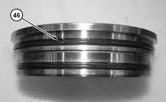 Illustration 7
g02722264
8. Install shaft assembly (49) .
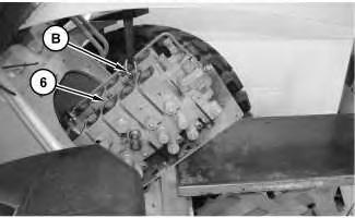
9. Use Tooling (B) in order to install retaining ring (48) .
Illustration 8
g02722263
10. Install lip seals (47) .
Illustration 9
g02722262
Illustration 7
g02722264
8. Install shaft assembly (49) .
9. Use Tooling (B) in order to install retaining ring (48) .
Illustration 8
g02722263
10. Install lip seals (47) .
Illustration 9
g02722262
 11. Install O-ring seals (46) .
Illustration 10
g02722261
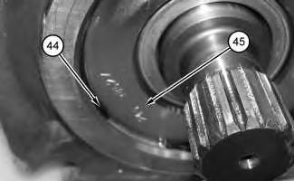
12. Install cover (45) and retaining ring (44) .
Illustration 11
g02722258
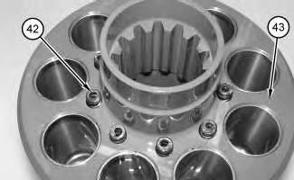
13. Install springs (42) into barrel (43) .
11. Install O-ring seals (46) .
Illustration 10
g02722261
12. Install cover (45) and retaining ring (44) .
Illustration 11
g02722258
13. Install springs (42) into barrel (43) .
Illustration 12 g02722254
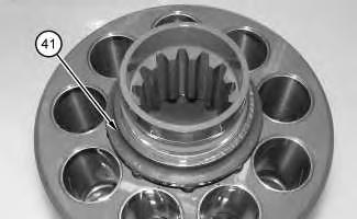
14. Install retainer (41) .
Illustration 13 g02722252
15. Install bearing (40) .
Illustration 14 g02722250
16. Install pistons (38) into retainer (39) .
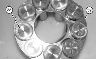
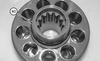
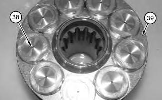
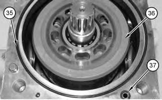
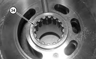 Illustration 15 g02722249
17. Install pistons (38) and retainer (39) into the barrel assembly.
Illustration 16 g02722248
18. Install barrel assembly (36), O-ring seal (35), and O-ring seal (37) .
Illustration 17 g02722245
19. Lower the temperature of bearing (34) .
Illustration 15 g02722249
17. Install pistons (38) and retainer (39) into the barrel assembly.
Illustration 16 g02722248
18. Install barrel assembly (36), O-ring seal (35), and O-ring seal (37) .
Illustration 17 g02722245
19. Lower the temperature of bearing (34) .
20. Install bearing (34) into the port block assembly .
21. Apply Tooling (D) to the back side of port plate (33) .
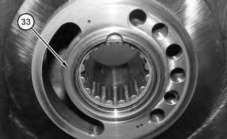
22. Install port plate (33) onto the port block assembly .
Improper assembly of parts that are spring loaded can cause bodily injury.
To prevent possible injury, follow the established assembly procedure and wear protective equipment.
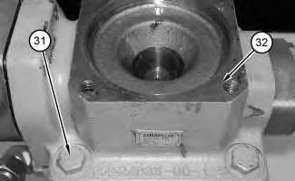
23. Install port block assembly (32) and bolts (31) .
Illustration 18 g02722244 Illustration 19 g02722243Improper assembly of parts that are spring loaded can cause bodily injury.
To prevent possible injury, follow the established assembly procedure and wear protective equipment.
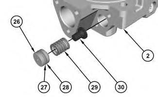 Illustration 20
g02722232
24. Install guide (30), spring (29), backup ring (27), O-ring seal (28), and plug (26) into pump control head (2) .
Illustration 21
g02722228
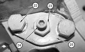
25. Install cover (25), bolts (22), adjustment screw (24), and locknut (23) .
Illustration 20
g02722232
24. Install guide (30), spring (29), backup ring (27), O-ring seal (28), and plug (26) into pump control head (2) .
Illustration 21
g02722228
25. Install cover (25), bolts (22), adjustment screw (24), and locknut (23) .
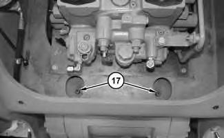
26. Install backup ring (18), O-ring seal (19), onto piston (17) .
27. Install spool (21), sleeve (20), and piston (17) into pump control head (2) .
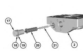
28. Install the cover, bolts (14), adjustment screw (15), and locknut (16) .
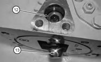
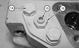 Illustration 22
g02722205
Illustration 23
g01145877
Illustration 24
g01145875
Illustration 22
g02722205
Illustration 23
g01145877
Illustration 24
g01145875
29. Apply Tooling (C) to the threads of piston (12) .
30. Install piston (12) and ball (13). Tighten piston (12) to a torque of 350 ± 30 N·m (258 ± 22 lb ft).
Note: Do not use an impact wrench in order to install piston (12) .
Note: Allow Tooling (C) to dry for 4 hours at room temperature.
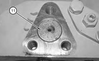
31. Install the O-ring seal, the backup ring, and piston (11) .
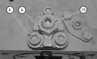
32. Install the cover, bolts (8), adjustment screw (10), and locknut (9) .
Illustration 25 g01145874 Illustration 26 g01145873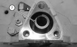
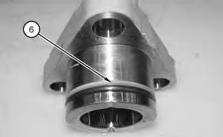
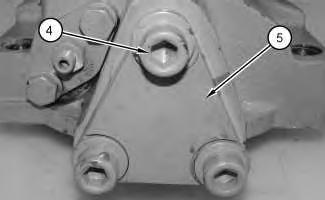 Illustration 27 g01145872
33. Install spring (7) .
Illustration 28 g01145871
34. Install O-ring seal (6) and the backup ring.
Illustration 29 g01145870
Illustration 27 g01145872
33. Install spring (7) .
Illustration 28 g01145871
34. Install O-ring seal (6) and the backup ring.
Illustration 29 g01145870
Improper assembly of parts that are spring loaded can cause bodily injury.
To prevent possible injury, follow the established assembly procedure and wear protective equipment.
g01145869
Illustration 31
End By: Install the pump.
g01145867
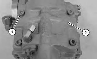
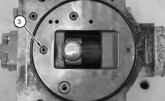
35. Install cover (5) and bolts (4) . Illustration 30 36. Install O-ring seals (3) . 37. Install head (2) and bolts (1) .Shutdown SIS
Previous Screen
Product: WHEEL LOADER
Model: 962K WHEEL LOADER T6A
Configuration: 962K Wheel Loader T6A00001-UP (MACHINE) POWERED BY C7.1 Engine
Disassembly and Assembly
950K and 962K Wheel Loaders Machine Systems
Electrohydraulic Control - Remove and Install
SMCS - 5702-010
Removal Procedure Table 1
Required Tools
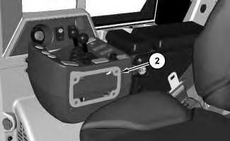
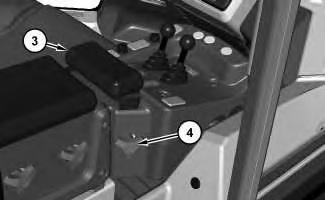
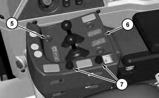 Illustration 2
g02486722
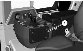
2. Remove plate (2).
Illustration 3
g02486738
3. Loosen knob (4) and remove arm rest (3).
Illustration 4
g02486756
4. Remove screws (5) and (6). Disconnect harness assemblies from switch assemblies (7).
Illustration 2
g02486722
2. Remove plate (2).
Illustration 3
g02486738
3. Loosen knob (4) and remove arm rest (3).
Illustration 4
g02486756
4. Remove screws (5) and (6). Disconnect harness assemblies from switch assemblies (7).
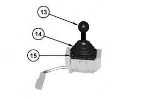
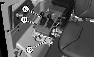
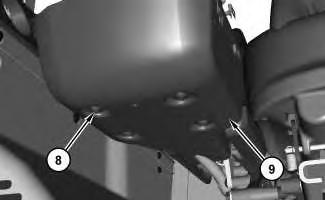 Illustration 5
g02487117
5. Remove screws (8) and cover (9).
Illustration 6 g02487136
6. Disconnect harness assemblies (12). Remove screws (11) and electrohydraulic controls (10).
Illustration 7 g02487617
7. Remove knob (13), screws (15), and boot (14).
Illustration 5
g02487117
5. Remove screws (8) and cover (9).
Illustration 6 g02487136
6. Disconnect harness assemblies (12). Remove screws (11) and electrohydraulic controls (10).
Illustration 7 g02487617
7. Remove knob (13), screws (15), and boot (14).
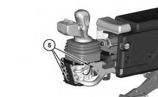
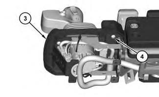
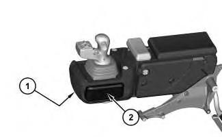
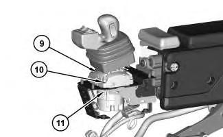
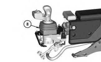
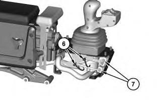

 Illustration 1
g02620276
Illustration 1
g02620276


 Illustration 5
g02627777
7. Remove bracket assemblies (9) from frame assembly (10). Reposition tube assemblies (5) out of the way. Repeat for the opposite side.
Illustration 6
g02627519
8. Disconnect tube assemblies (11) and hose assemblies (12) .
Illustration 7
g02628759
Illustration 5
g02627777
7. Remove bracket assemblies (9) from frame assembly (10). Reposition tube assemblies (5) out of the way. Repeat for the opposite side.
Illustration 6
g02627519
8. Disconnect tube assemblies (11) and hose assemblies (12) .
Illustration 7
g02628759