1 minute read
Installation Procedure (Joystick Control)

from Caterpillar Cat 962K Wheel Loader (Prefix T6A) Service Repair Manual Instant Download
by kmd9iso9dkk
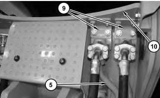
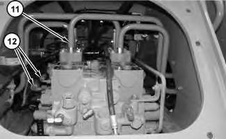
1. Install joy stick (9) in the reverse order of removal.
a. Tighten nuts (11) to the following torque 6.5 ± 0.5 N·m (58 ± 4 lb in).
Advertisement
Previous Screen
Product: WHEEL LOADER
Model: 962K WHEEL LOADER T6A
Configuration: 962K Wheel Loader T6A00001-UP (MACHINE) POWERED BY C7.1 Engine
Disassembly and Assembly
950K and 962K Wheel Loaders Machine Systems
Main Control Valve - Remove and Install
SMCS - 5051-010
Removal Procedure Table 1
Required Tools
Hot oil and components can cause personal injury.
Do not allow hot oil or components to contact skin.
Shutdown SIS
Hydraulic oil pressure can remain in the hydraulic system on this machine after the engine and pump have been stopped. Serious injury can result if this pressure is not released before any service is done on the hydraulic systems. In order to prevent possible injury, release the hydraulic system pressure before working on any fitting, hose, or hydraulic component.
Lower all attachments to the ground before service is started. If the hydraulic system must be serviced, tested, or adjusted with the attachment in the raised position, the attachments and lift cylinders must be supported properly.
Always move the machine to a location away from the travel of other machines. Be sure that other personnel are not near the machine when the engine is running and tests or adjustments are being made.
1. Use Tooling (A) in order to support lift arms (1) .
2. Release the system hydraulic pressure.
3. Drain the implement hydraulic system. Refer to Operation and Maintenance Manual, "Hydraulic System Oil - Change" for the correct procedure.

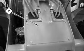
Illustration 2 g02620285
4. Remove cover assembly (2) .
Illustration 3 g02627227
5. Disconnect all hose assemblies (3) from the front of main control valve (6). Disconnect tube assemblies (5) and harness assemblies (4) from main control valve. (6) .
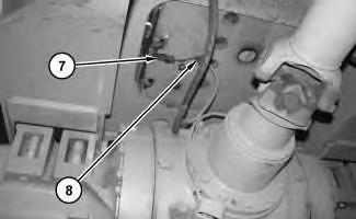
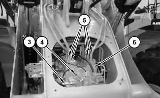
Illustration 4 g02627559
Bottom view of main control valve
6. Disconnect harness assembly (7) and remove cable strap (8) .
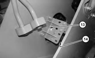
9. Separate bracket (13) from the frame assembly. Reposition tubes (14) in order to remove the main control valve. Repeat for the opposite side.


10. Disconnect all hose assemblies (15) from the rear of the main control valve. Remove cable straps (16) from the harness assembly.
Bottom view
Suggest:
If the above button click is invalid.
Please download this document first, and then click the above link to download the complete manual.
Thank you so much for reading