Service Repair Manual Model
321D LCR EXCAVATOR
Shutdown SIS
Previous Screen
Product: EXCAVATOR
Model: 321D LCR EXCAVATOR NAS
Configuration: 321D LCR Excavator NAS00001-UP (MACHINE) POWERED BY C6.4 Engine
Disassembly and Assembly
C6.4 Engine for Caterpillar Built Machines
Inlet Manifold - Remove and Install
SMCS - 1058-010
Removal Procedure Table 1
Required Tools
Tool Part Number Part Description Qty
A 138-7573 Link Bracket 1
Start By:
A. Remove the fuel manifold. Refer to Disassembly and Assembly, "Fuel Manifold (Rail)Remove".
NOTICE
Keep all parts clean from contaminants.
Contaminants may cause rapid wear and shortened component life.
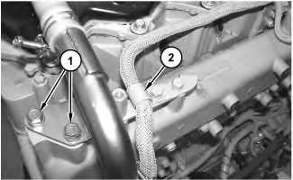
1. Remove bolts (1) and remove clip (2) .
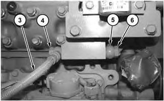
2. Remove bolt (4) . Disconnect hose assembly (3) and the washers. Discard the washers.
3. Remove bolt (6) . Disconnect hose assembly (5) and the washers. Discard the washers.
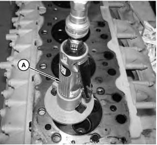
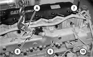
Illustration 1 g01375420 Illustration 2 g01375421 Illustration 3 g013754224. Attach Tooling (A) and a suitable lifting device to inlet manifold (9) . The weight of inlet manifold (9) is approximately 29 kg (65 lb).
5. Remove clip (7) and clip (8) .
6. Remove bolts (10) . Use Tooling (A) and the suitable lifting device in order to remove inlet manifold (9) and the gasket.
7. If necessary, remove the air inlet heater. Refer to Disassembly and Assembly, "Air Inlet Heater - Remove".
Installation Procedure Table 2
Required Tools
A
NOTICE
Keep all parts clean from contaminants.
Contaminants may cause rapid wear and shortened component life.
Note: Check the gaskets for wear or for damage. Replace the components, if necessary.
1. If necessary, install the air inlet heater. Refer to Disassembly and Assembly, "Air Inlet Heater - Install".
2. Attach Tooling (A) and a suitable lifting device to inlet manifold (9) . The weight of inlet manifold (9) is approximately 29 kg (65 lb). Position the gasket. Use Tooling (A) and the suitable lifting device in order to position inlet manifold (9) to the engine. Install bolts (10) . Tighten bolts (10) to a torque of 18 ± 2 N·m (13 ± 1 lb ft).
3. Install clips (8) and (7) .
4. Install new washers and connect hose assembly (5) . Install bolt (6) . Tighten bolt (6) to a torque of 34 ± 4 N·m (25 ± 3 lb ft).
5. Install new washers and connect hose assembly (3) . Install bolt (4) . Tighten bolt (4) to a torque of 34 ± 4 N·m (25 ± 3 lb ft).
6. Install clip (2) and install bolts (1) .
End By: Install the fuel manifold. Refer to Disassembly and Assembly, "Fuel Manifold (Rail)Install".
Illustration 5
g01375421
Illustration 6
g01375420
Shutdown SIS
Previous Screen
Product: EXCAVATOR
Model: 321D LCR EXCAVATOR NAS
Configuration: 321D LCR Excavator NAS00001-UP (MACHINE) POWERED BY C6.4 Engine
Disassembly and Assembly
C6.4 Engine for Caterpillar Built Machines Media
Inlet and Exhaust Valve Springs - Remove and Install
SMCS - 1108-010
Removal Procedure
Table 1
Required Tools
Tool
A 9U-6195 Valve Spring Compressor 1
B 9U-6198 Crankshaft Turning Tool 1
Start By:
a. Remove the rocker shaft assembly. Refer to Disassembly and Assembly, "Rocker Shaft and Pushrod - Remove".
b. Remove the valve mechanism cover base. Refer to Disassembly and Assembly, "Valve Mechanism Cover Base - Remove and Install".
NOTICE
Keep all parts clean from contaminants.
Contaminants may cause rapid wear and shortened component life.
Note: The following procedure should be adopted in order to remove the valve springs when the cylinder head is installed to the engine.
Note: Ensure that the appropriate piston is at top dead center before the valve spring is removed. Failure to ensure that the piston is at top dead center may allow the valve to drop into the cylinder bore.
Personal injury can result from being struck by parts propelled by a released spring force.
Make sure to wear all necessary protective equipment.
Follow the recommended procedure and use all recommended tooling to release the spring force.
NOTICE
Plug the apertures for the push rods in the cylinder head in order to prevent the entry of loose parts into the engine.
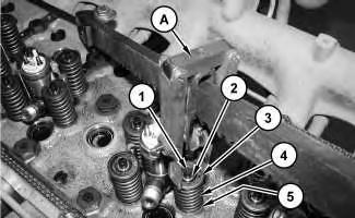 Illustration 1
g01376301
Illustration 1
g01376301
NOTICE
Ensure that the valve spring is compressed squarely or damage to the valve stem may occur.
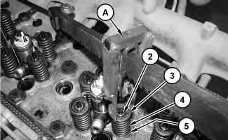
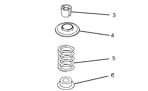
1. Install Tooling (A) into position on the cylinder head in order to compress a valve spring (4) for the appropriate piston.
2. Use Tooling (A) in order to compress valve spring (4) and open valve (1) slightly.
Note: Do not compress valve spring (4) so that valve spring retainer (3) touches valve stem seal (5).
3. Use Tooling (B) in order to rotate the crankshaft carefully, until the piston touches the valve.
Note: Do not use excessive force to turn the crankshaft. The use of force can result in bent valve stems.
4. Continue to rotate the crankshaft and gradually release the pressure on Tooling (A) until the piston is at the top dead center position. The valve is now held in a position that allows valve spring (4) to be safely removed.
Note: Valve springs must be replaced in pairs for the inlet valve or the exhaust valve of each cylinder. If all valve springs require replacement the procedure can be carried out on two cylinders at the same time. The procedure can be carried out on the following pairs of cylinders. 1 with 6, 2 with 5 and 3 with 4. Ensure that all of the valve springs are installed before changing from one pair of cylinders to another pair of cylinders.

NOTICE
Do not turn the crankshaft while the valve springs are removed.
5. Apply sufficient pressure to Tooling (A) in order to allow removal of valve keepers (2).
Note: Do not compress valve spring (4) so that valve spring retainer (3) touches valve stem seal (5).
Remove valve keepers (2).
6. Slowly release the pressure on Tooling (A).
7. Remove valve spring retainer (3) and remove valve spring (4).
8. If necessary, remove valve stem seals (5).
9. Remove Tooling (A).
Note: The installation of each set of valve springs (4) must be completed before attempting to remove the next set of valve springs (4).
Installation Procedure
Required
NOTICE
Keep all parts clean from contaminants.
Contaminants may cause rapid wear and shortened component life.
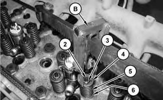
1. The outer face of the valve guides must be clean and dry before installing the valve stem seal (5). Install new valve stem seal (5) onto the valve guide.
2. Install valve spring (4) onto the cylinder head. Position valve spring retainer (3) on valve spring (4).
3. Install Tooling (A) in the appropriate position on the cylinder head in order to compress valve spring (4).
Improper assembly of parts that are spring loaded can cause bodily injury.
To prevent possible injury, follow the established assembly procedure and wear protective equipment.
Illustration 3 g01376913 Illustration 4 g013763024. Apply sufficient pressure to Tooling (A) in order to install valve keepers (2). Do not compress valve spring (4) so that valve spring retainer (3) touches valve stem seal (5).
5. Carefully release the pressure on Tooling (A).
End By:
a. Install the valve mechanism cover base. Refer to Disassembly and Assembly, "Valve Mechanism Cover Base - Remove and Install".
b. Install the rocker shaft assembly. Refer to Disassembly and Assembly, "Rocker Shaft and Pushrod - Install". Copyright 1993 - 2019 Caterpillar Inc. All Rights Reserved. Private Network For SIS Licensees.
Previous Screen
Product: EXCAVATOR
Model: 321D LCR EXCAVATOR NAS
Configuration: 321D LCR Excavator NAS00001-UP (MACHINE) POWERED BY C6.4 Engine
Disassembly and Assembly
C6.4 Engine for Caterpillar Built Machines Media
Inlet and Exhaust Valves - Remove and Install
SMCS - 1105-010
Removal Procedure Table 1
Required Tools
Start By:
a. Remove the cylinder head. Refer to Disassembly and Assembly, "Cylinder HeadRemove".
NOTICE
Keep all parts clean from contaminants.
Contaminants may cause rapid wear and shortened component life.
Note: Note the location and orientation of all components for assembly purposes.
1. Clean the bottom face of the cylinder head. Check the depth of the valves below the face of the cylinder head before the valve springs are removed. Refer to Specifications, "Cylinder Head Valves" for the correct dimensions.
2. Place a temporary identification mark on the heads of the valves in order to identify the correct position.
3. Use a suitable lifting device in order to position cylinder head (1) onto Tooling (A) with the valve springs upward. The weight of cylinder head (1) is approximately 113 kg (250 lb).
Note: Ensure that cylinder head (1) is kept on a clean, soft surface in order to prevent damage to the machined face.
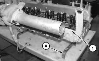 Illustration 1
g01376164
Illustration 2
g01376174
Illustration 1
g01376164
Illustration 2
g01376174
Personal injury can result from being struck by parts propelled by a released spring force.
Make sure to wear all necessary protective equipment.
Follow the recommended procedure and use all recommended tooling to release the spring force.
4. Install Tooling (B) on cylinder head (1) in order to compress valve spring (5).
NOTICE
Ensure that the valve spring is compressed squarely or damage to the valve stem may occur.
5. Apply sufficient pressure to Tooling (B) in order to remove valve keepers (3). Do not compress the spring so that valve spring retainer (4) touches valve stem seal (6).
6. Slowly release the pressure on Tooling (B).
7. Remove valve spring retainer (4). Remove valve spring (5). Remove valve (2).
8. Use Tooling (C) in order to remove valve stem seal (6).
9. Repeat Steps 4 through 7 for the remaining valves.