3 minute read
Installation Procedure

from Caterpillar Cat 321D LCR EXCAVATOR (Prefix NAS) Service Repair Manual Instant Download
by kmd9iso9dkk
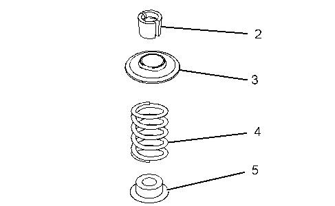
Table 2
Required Tools
Advertisement
Tool Part Number
Part Description Qty
A 8S-6691 Cylinder Head Repair Stand 1
B 9U-6195 Valve Spring Compressor Gp 1
D 312-8755 Valve Stem Seal Installer 1
Notice
Keep all parts clean from contaminants.
Contaminants may cause rapid wear and shortened component life.
1. Clean all components of the cylinder head assembly. Ensure that all ports, all coolant passages, and all lubrication passages in the cylinder head are free from debris. Follow Steps 1.a through 1.d in order to inspect the components of the cylinder head assembly. Replace any components that are worn or damaged.
a. Inspect the cylinder head for wear and for damage. Refer to Testing and Adjusting, "Cylinder Head Inspect".
b. Inspect the valve seats for wear and for damage. Refer to Specifications, "Cylinder Head Valves" for further information.
c. Inspect the valve guides for wear and for damage. Refer to Specifications, "Cylinder Head Valves" and Testing and Adjusting, "Valve Guide - Inspect" for further information.
d. Inspect the valves for wear and for damage. Refer to Specifications, "Cylinder Head Valves ".
e. Inspect valve springs (5) for damage and for the correct length. Refer to Specifications, "Cylinder Head Valves ".
2. Lubricate the stem of valve (2) with clean engine oil. Install valve (2) in the appropriate position in the cylinder head.
3. The outer face of the valve guides must be clean and dry before installing the valve stem seal (6). Use Tooling (C) in order to install new valve stem seal (6) onto the valve guide.
4. Install valve spring (5) onto the cylinder head. Position valve spring retainer (4) on valve spring (5).
5. Install Tooling (B) in the appropriate position on cylinder head (1) in order to compress valve spring (5).

Improper assembly of parts that are spring loaded can cause bodily injury.
To prevent possible injury, follow the established assembly procedure and wear protective equipment.
6. Apply sufficient pressure to Tooling (B) in order to install valve keepers (3). Do not compress spring (5) so that valve spring retainer (4) touches valve stem seal (6).
7. Carefully release the pressure on Tooling (B).
8. Repeat Steps 2 through 7 for the remaining valves.
End By: a. Install the cylinder head. Refer to Disassembly and Assembly, "Cylinder Head - Install".
Copyright 1993 - 2019 Caterpillar Inc.
All Rights Reserved. Private Network For SIS Licensees.
Shutdown SIS
Previous Screen
Product: EXCAVATOR
Model: 321D LCR EXCAVATOR NAS
Configuration: 321D LCR Excavator NAS00001-UP (MACHINE) POWERED BY C6.4 Engine
Disassembly and Assembly
C6.4 Engine for Caterpillar Built Machines Media
Inlet and Exhaust Valve Guides - Remove and Install
SMCS - 1104-010
Removal Procedure Table 1
Required Tools
Start By:
A. Remove the inlet and exhaust valves. Refer to Disassembly and Assembly, "Inlet and Exhaust Valves - Remove and Install".
B. Remove the electronic unit injectors. Refer to Disassembly and Assembly, "Electronic Unit Injector - Remove".
NOTICE
Keep all parts clean from contaminants.
Contaminants may cause rapid wear and shortened component life.
Care must be taken to ensure that fluids are contained during performance of inspection, maintenance, testing, adjusting, and repair of the product. Be prepared to collect the fluid with suitable containers before opening any compartment or disassembling any component containing fluids.
Refer to Special Publication, NENG2500, "Dealer Service Tool Catalog" for tools and supplies suitable to collect and contain fluids on Cat products.
Dispose of all fluids according to local regulations and mandates.
Note: Refer to Special Instructions, SMHS7953-00, "Use of Valve Seat Insert Puller Group" to aid with the removal of the inlet and exhaust valve seats.
1. Attach Tooling (B) , Tooling (C) , and a suitable lifting device to cylinder head (1) . Use Tooling (B) , Tooling (C) , and the suitable lifting device in order to turn over cylinder head (1) by 180° onto Tooling (D) .
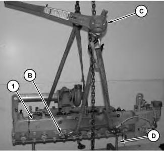
Illustration 2 g01377121
2. Use Tooling (A) in order to remove valve guides (2) (not shown).

Installation Procedure Table 2
Required Tools
Keep all parts clean from contaminants.
Contaminants may cause rapid wear and shortened component life.
Illustration 3 g01377130
1. Lubricate the outside of valve guides (2) (not shown) with clean engine oil.
2. Use Tooling (E) in order to install new valve guides (2) . Install valve guide (2) so that valve guide (2) protrudes 16.000 mm (0.6299 inch) above Surface (X) of cylinder head (1) .

End By: a. Install the electronic unit injectors. Refer to Disassembly and Assembly, "Electronic Unit Injector - Install". b. Install the inlet and exhaust valves. Refer to Disassembly and Assembly, "Inlet and Exhaust Valves - Remove and Install".
Copyright 1993 - 2019 Caterpillar Inc.
All Rights Reserved. Private Network For SIS Licensees.
Wed Oct 9 22:38:13 UTC+0800 2019
Shutdown SIS
Previous Screen
Product: EXCAVATOR
Model: 321D LCR EXCAVATOR NAS
Configuration: 321D LCR Excavator NAS00001-UP (MACHINE) POWERED BY C6.4 Engine
Disassembly and Assembly
C6.4 Engine for Caterpillar Built Machines
Inlet and Exhaust Valve Seat Inserts - Remove and Install
SMCS - 1103-010
Removal Procedure Table 1
Required Tools
Start By:
A. Remove the inlet and exhaust valves. Refer to Disassembly and Assembly, "Inlet and Exhaust Valves - Remove and Install".
B. Remove the electronic unit injectors. Refer to Disassembly and Assembly, "Electronic Unit Injectors - Remove".
NOTICE
Keep all parts clean from contaminants.
Suggest:
If the above button click is invalid.
Please download this document first, and then click the above link to download the complete manual.
Thank you so much for reading