


•
•
•
•
•


•
•
•
•
•


North American Society for Trenchless Technology’s 2024 Project of the Year Award.


Congratulations to our team, including Jason Lueke, Chris Lamont, Sam Saunders, Ryan Krausher, Dusanka Stevanovic, Caitlin Lou, and Greg Walker, for their contributions to this award-winning project. The 99th Avenue Sanitary Trunk Sewer in Edmonton, AB has been a critical component of the City of Edmonton’s wastewater collection system since the 1970s. The project to rehabilitate the aging sewer system was led by Shanghai Construction Group, and included complex design components provided by Associated Engineering, for hand tunnel connections, manhole structures, and inflow bypass and abandonment plans. This project also recently received an Award of Excellence from the Consulting Engineers of Alberta. www.ae.ca

Well, we have finally reached spring. The NW Chapter has been busy over the fall and winter. The upcoming Symposium on June 2–3 in Calgary has kept our Calgary Section group hopping to organize and promote the event. We are offering two NASTT Trenchless 101 courses on Monday: Introduction to Rehabilitation; and, Introduction to New Installations. On Tuesday, ten technical presentations and opportunities to network will fill the day. We expect ten participants in the mini-tradeshow, and the team has done a great job in securing sponsors for the event.

We plan to expand opportunities for education across our region, a task that is daunting given the area we span. In Alberta we have a critical mass that provides the horsepower to host events such as the Symposium and the technical lunch programs in Edmonton and Calgary. We have also worked with the Winnipeg Student Chapter to offer technical sessions, with more planned in the future. In Saskatoon and Regina, we are aiming to offer technical sessions or courses to these Cities to bring trenchless practitioners and students together not only for the technical aspects, but also networking opportunities.
We have made great progress in reviving the Edmonton Section, with many new volunteers joining the old guard to bring us new ideas and ‘legs’ to get things done. Matthew Devitt, from Stantec is the new Edmonton Section leader, and he has done a great job in kickstarting our local group. We have some keen members that are undertaking tasks to help us evolve, following the Calgary Section’s successes.
Our NW Chapter Board has also experienced changes. Our long-time treasurer, Keith Moggach, has relinquished the treasury to Craig Pass. We will be making additional changes in October as Executive

members retire or move to new positions, as well as retiring or renewing board members. There are opportunities to get involved at the Board or Local Section levels, with varying time commitments.
Looking at planned events for the next year, we will be continuing the Technical Luncheon programs in Calgary and Edmonton in the fall. We are also planning on less formal social events such as after work mixers, and possibly site visits in the summer and early fall.
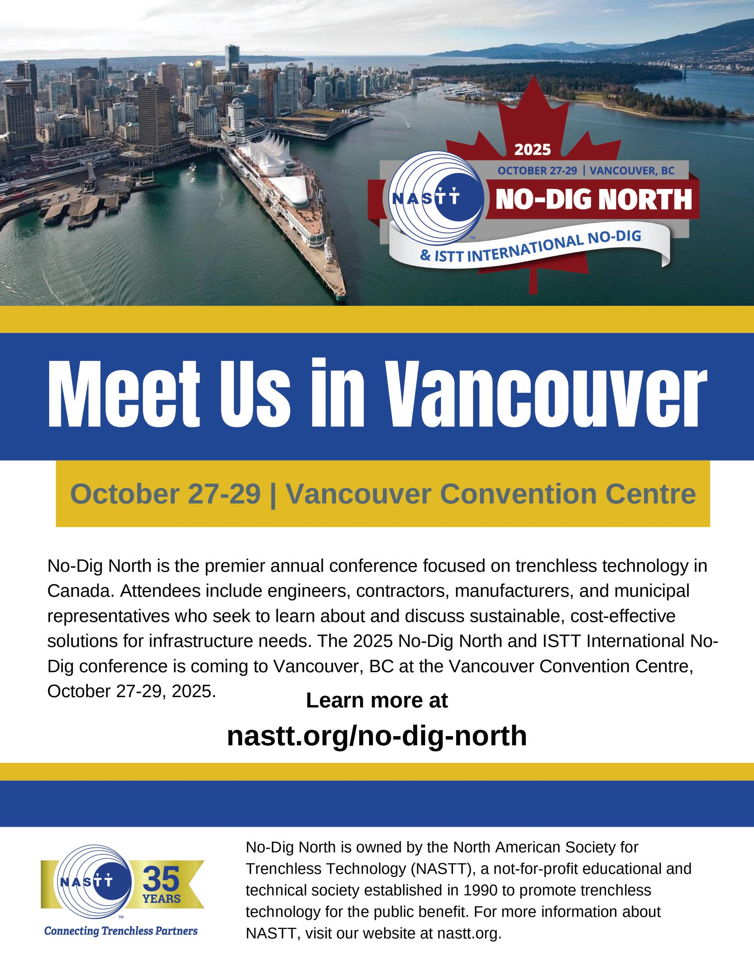
No-Dig North will be held in Vancouver from October 27–30, 2025. This will be a unique opportunity to meet and learn from trenchless experts from around the world, since it is a joint meeting with ISTT. Several NASTT courses will also be offered at the event.
In spring 2026, CUIIC is planning to host the Annual Pipe Rehabilitation Academy

in Edmonton. This will also be a great opportunity to present, learn and network.
Going out a bit further, mark your calendars for fall 2026 when No-Dig North will be held in Calgary. Look out for calls for papers, volunteer opportunities and attendance information early in 2026. Please reach out to any of our Board members with suggestions on how we can improve contact and education. We are always happy to discuss the NW Chapter activities, and needs with respect to volunteers. We have a great group of trenchless experts and practitioners that are willing to share experiences and knowledge. I hope to have the chance to meet many of you at some of the planned events. Enjoy the summer, and fall.
George Bontus, P.Eng. Chair, NASTT Northwest Chapter


As we continue with a busy and exciting year for the Northwest Chapter, I want to take a moment to thank all of you for your ongoing commitment to the growth and success of trenchless technology in your region. The energy, innovation, and collaboration coming out of your Chapter continue to raise the bar across Canada – and beyond.
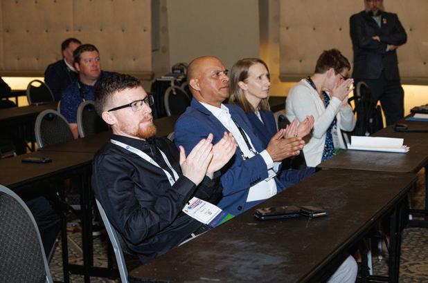
One of your most consistent and valued initiatives is the series of technical luncheons you’re hosting in both Calgary and Edmonton. These events have become a cornerstone of your Chapter’s eff orts to share knowledge, build community, and keep pace with evolving technologies and project experiences. I always looked forward to attending these luncheons as they were an excellent opportunity to stay informed, engage with experts, and connect with peers who share a passion for advancing trenchless solutions. I encourage you to attend if you haven’t already, and if you have, bring colleagues along next time.
“The international stage will bring new perspectives, innovations, and opportunities for collaboration that will benefit the industry for years to come.”
Looking ahead, the NASTT 2025 No-Dig North will return to Vancouver in October with its signature blend of technical excellence, industry insights, and unmatched networking. The event continues to grow in both attendance and impact, and I’m proud that this event was born in the Northwest Chapter and your continuing role in its ongoing success. This year’s No-Dig North will be even more exciting as the ISTT International No-Dig is being held in partnership with the event. This is a tremendous opportunity for our members to engage with global leaders in trenchless technology. The international stage will bring new perspectives, innovations, and

opportunities for collaboration that will benefit the industry for years to come.
These Regional and National events reinforce the Northwest Chapter’s role as a driving force within the trenchless community. Whether it’s through monthly luncheons or international conferences, you’re building a network that’s informed, connected, and positioned for long-term success.
Thank you once again for your participation and support. I look forward to seeing many of you at our upcoming luncheons and in Vancouver this fall.
Greg Tippett NASTT Board of Directors Chair


The North American Society for Trenchless Technology (NASTT) is now accepting abstracts for its 2026 No-Dig Show in Palm Springs, CA at the Palm Springs Convention Center March 29-April 2, 2026. Prospective authors are invited to submit a 250-word abstract outlining the scope of their paper and the principal points of benefit to the trenchless industry. The abstracts must be submitted electronically by June 30, 2025 on the NASTT website: nastt.org/no-dig-show


James P. Murphy P.Eng.
UniversalPegasus International, Calgary, AB
Matt Thompson, P.Eng.
BGC Engineering, Vancouver, BC
Alex Baumgard, P.Eng.
BGC Engineering, Vancouver, BC
Trevor Miles, P.Eng.
UniversalPegasus International, Calgary, AB
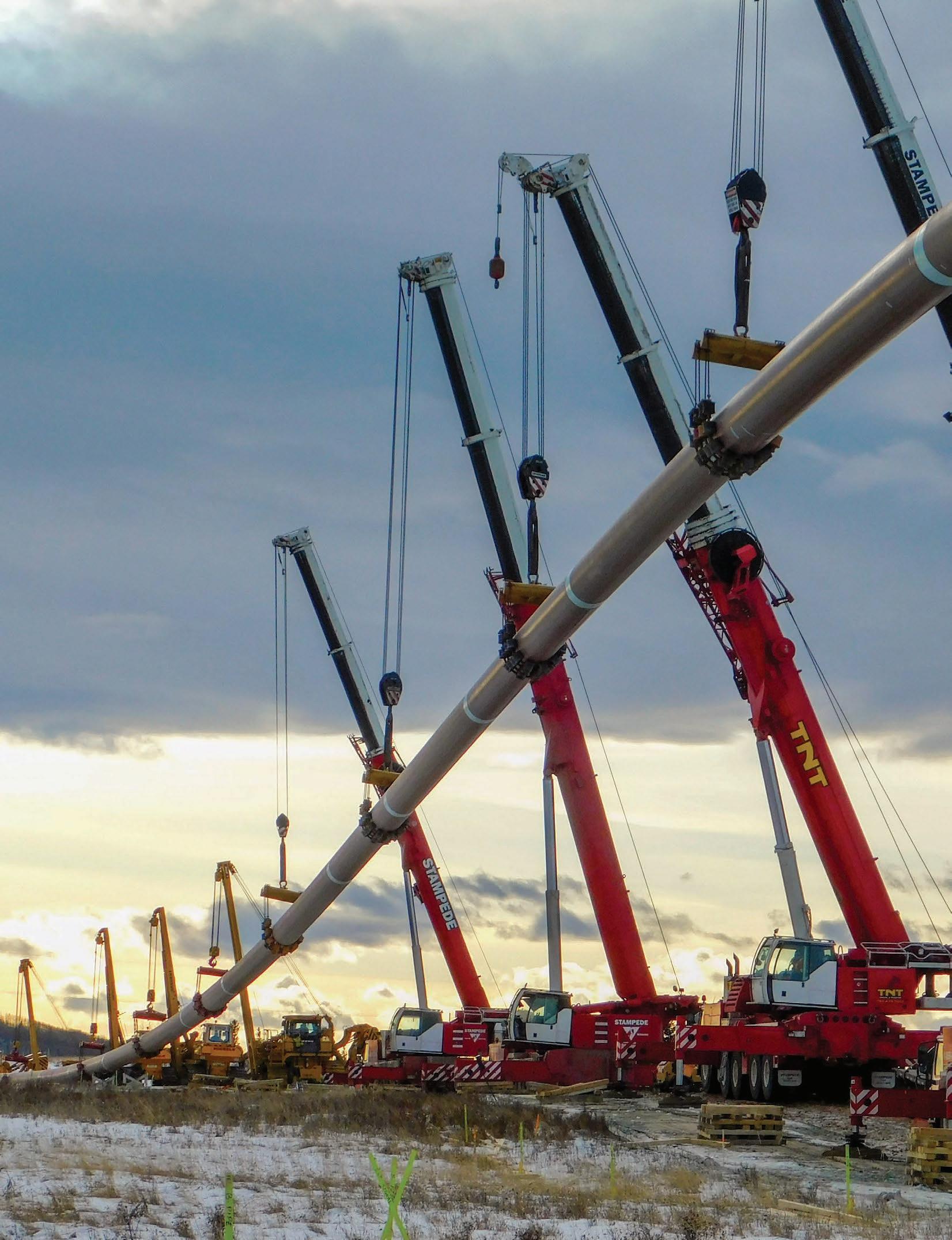
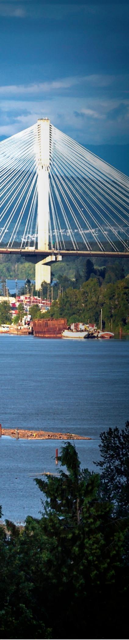
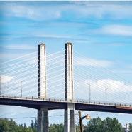
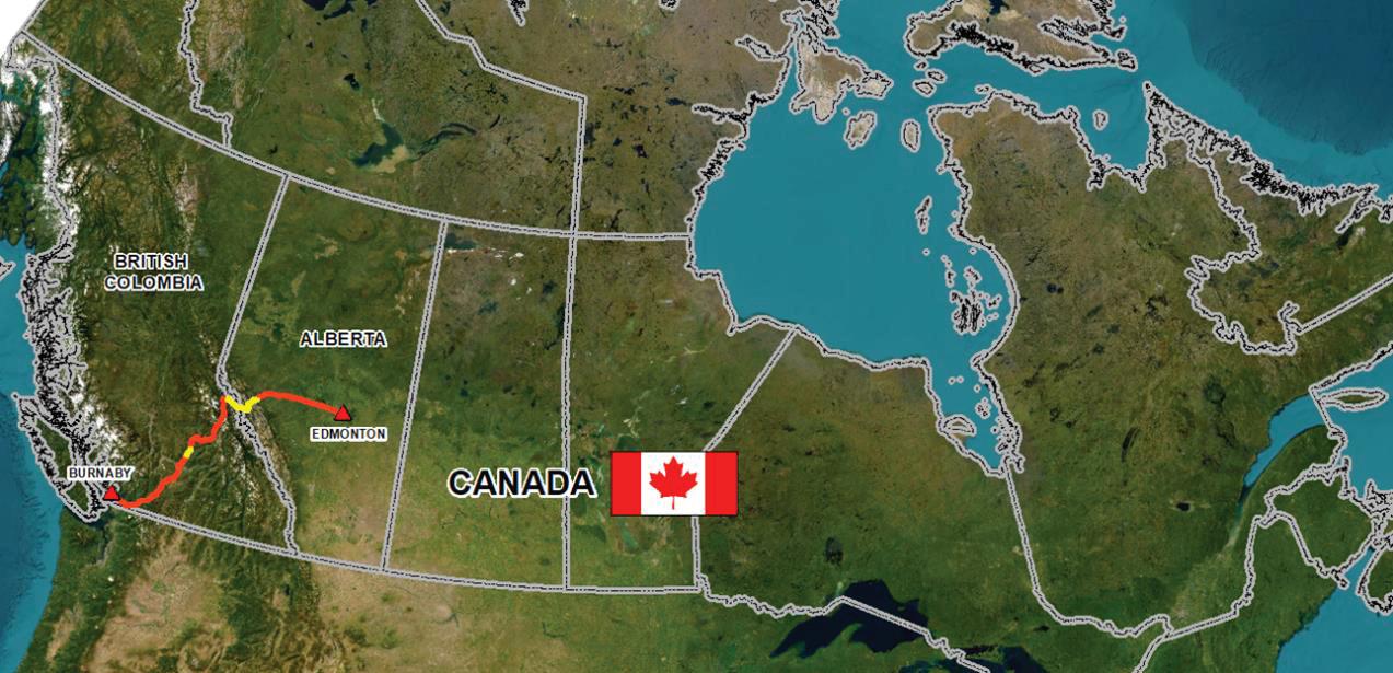
The Trans Mountain Expansion Project (TMEP or Project) pipeline is located in the two western provinces of Canada. The pipeline extends from Edmonton, Alberta to Burnaby, B.C., carrying oil from the Alberta oil sands to the Westridge Terminal in Burrard Inlet in Burnaby. The route generally follows the existing Trans Mountain Pipeline (TMPL) route. Figure 1 shows the location of the TMEP pipeline route relative to North America. Construction of the original Trans Mountain Pipeline (TMPL) was completed in 1953. This pipeline was constructed as an NPS 24 line to carry approximately 300,000 barrels per day (bpd). The TMPL continues to operate today and serves as the key transportation link between the Alberta oil sands and the west coast of North America. Construction of the TMPL pipeline system was a monumental engineering feat by any standard. It crosses some of the most rugged, mountainous terrains in the world as well as environmentally sensitive wetlands, waterways and parkland.
In 2008, Trans Mountain completed an Anchor Loop between Hinton, Alberta and Hargreaves, BC involving the twinning of a 158-kilometre section of the existing
Trans Mountain system. Th is included twinning a portion of the pipeline system crossing Jasper National Park and Mount Robson Provincial Park, both designated part of the Canadian Rocky Mountains Parks, a United Nations Educational, Scientific, and Cultural Organization (UNESCO) World Heritage Site. Between 2011 and 2024, Trans Mountain completed routing, design and construction of the TMEP, including the twinning of the existing 1,180 km pipeline between Edmonton, Alberta and Burnaby, BC. The pipeline system’s nominal capacity was increased from approximately 300,000 to 890,000 barrels per day. The TMEP also included three new berths at Westridge Marine Terminal, increasing access to tidewater and access to new markets. During the course of the development of the Project, 51 of the total 75 major trenchless crossings were ultimately designed and constructed using HDD and incorporated into the overall Project alignment. Identified early on in the Project as one of the most critical crossings, the Fraser River crossing is one of the major rivers of North America, situated on the border between the city of Coquitlam and Surrey, British Columbia.

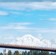
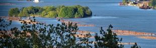
The pipeline route begins in Edmonton and traverses west through the Alberta Plains before crossing three different mountain ranges, the Rockies, Columbia and Cascade mountains. They are characterized by high topographic relief with rockfall and landslide deposits, glacial tills and bedrock exposures on the valley walls, and thick sequences of fluvial and glaciofluvial sediments in the bottom of valleys. After leaving the mountains towards the end of the route and the Pacific coast, the route spans the lowlands of the Fraser River Valley. The Fraser Valley is characterized by low topographic relief with fluvial and glacial sediments deposited by the Fraser River.
HDD has been used extensively on TMEP with a total of 51 completed on the Project. Horizontal Directional Drilling inherently has risk involved in the construction. As part of the planning of the Project, Universal Pegasus International (UPI), the Project’s pipeline engineering consultant, identified 11 of the higher risk HDD crossings on the Project. These were identified as higher risk due to a number of different factors, such as geotechnical, length of crossing, depth of crossing, access, as well as location of the crossing. One of the crossings that was identified as high risk was the HDD of the Fraser River, particularly due to the lack of an alternative crossing methodology. The crossing was much too long for a bored crossing, a bottom lay crossing was not an option, and a tunnel would have been very expensive and required more time to construct. Additionally, the Fraser River had been crossed using HDD a number of times, albeit with some difficulties. One of those crossings was the TMPL HDD crossing replacement constructed in 2004. The original TMPL crossing was constructed in 1953 by the bottom lay method. In most cases this method is no longer an acceptable method for a water crossing, but in addition, seismic considerations made a replacement necessary.
Routing at the Fraser was looked at very early on the Project. Typically, on greenfield projects the major river crossings are identified early; this was true of the Fraser River. The Project was required to follow the existing easement as much as possible. Therefore, the original Line 1 route across the river was reviewed extensively and was even considered for an especially long
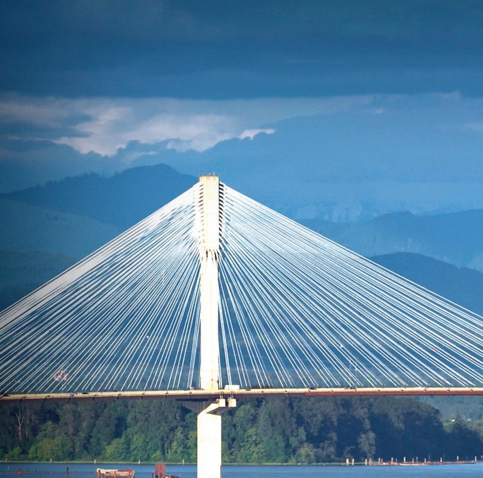
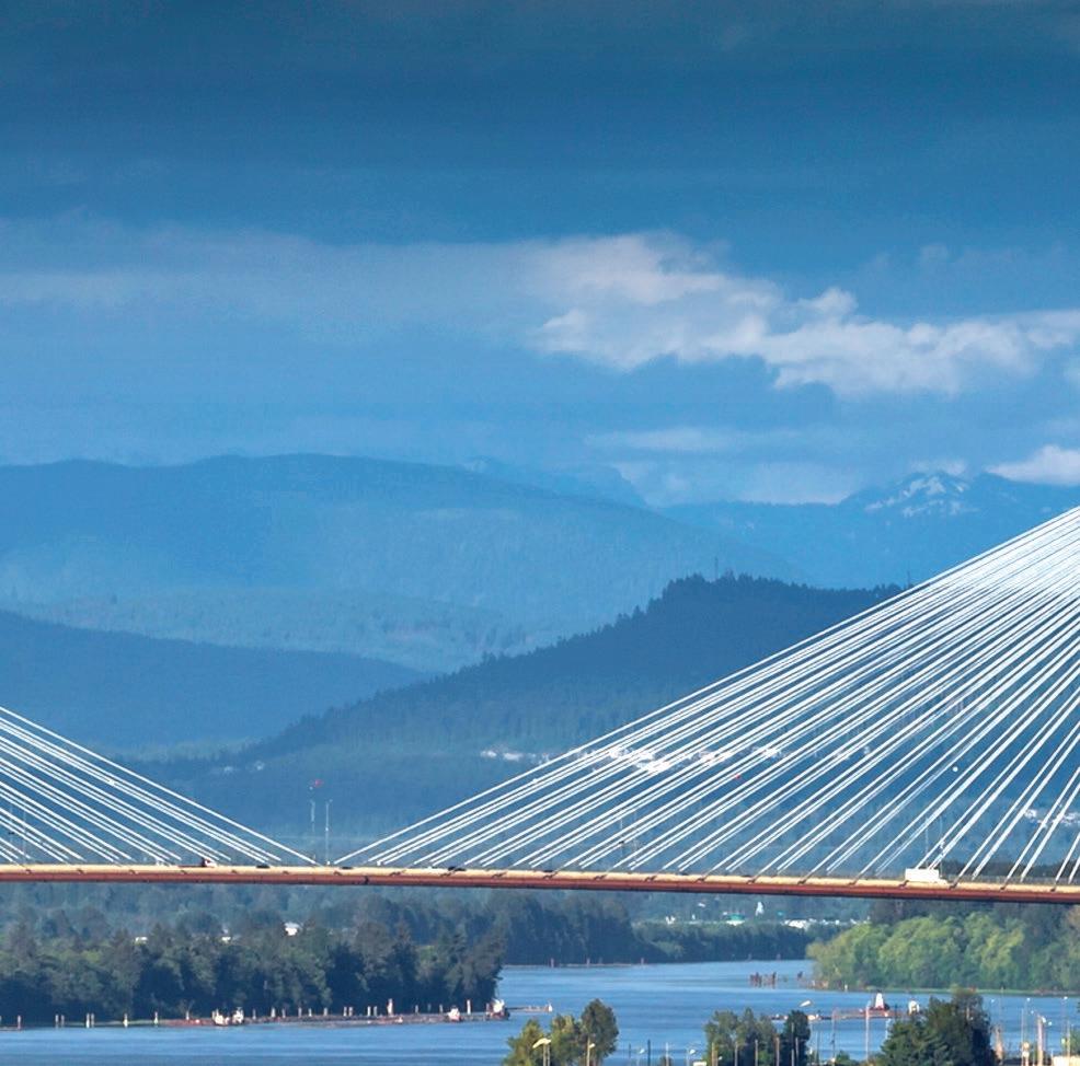
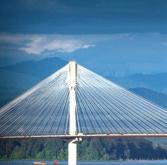
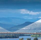
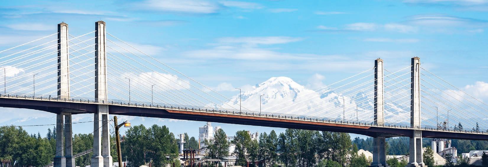
Direct Pipe crossing. However, it was decided that the development on the north side of the river now contained too much new infrastructure including the expansion of Highway 1 in conjunction with the replacement of the Port Mann Bridge, and there simply would not be sufficient room on the north side to lay down the pipe in sufficiently long segments. The other aspect was that all the previous HDD crossings were drilled within the upper sand layers. This sand would not have been suitable for numerous short pipe segments which would require multiple stops for welding of the 36-inch pipe. As a result, the crossing location was moved to a point just upstream of the new Port Mann bridge.
BGC Engineering Inc (BGC) has a long history of supporting Trans Mountain with the management of geohazards along the original NPS 24 pipeline system, dating back to the mid 1990s. Following a seismic vulnerability assessment in 1999, the existing NPS 24 TMPL Fraser River crossing located west (downstream) of the Port Mann bridge was determined to be at risk from liquefaction induced ground displacements on both the north and south banks which necessitated the replacement of the existing trenched crossing of the Fraser River. In 2002, TMPL retained BGC to conduct a geotechnical investigation for a proposed HDD replacement crossing utilizing the same TMPL right-of-way. The investigation consisted of both instream and onshore boreholes. Cone Penetration Testing (CPTs) were conducted onshore and mud rotary boreholes were conducted both onshore and within the Fraser River channel. The HDD replacement proceeded to construction in 2004. The HDD experienced relatively few challenges, but
those that were experienced included the temporary loss of the guidance signal near the HDD exit point due to a broken wire at the drill head and some loss of fluid when a permeable gravel deposit was encountered along the borepath. However, shortly after installation, a series of settlement and sinkholes developed on the south side which required remediation including an extensive ground improvement program to reestablish the soil density and strength around the areas of settlement and sinkholes (BGC, 2004). The selected TMEP (Line 2) crossing location benefitted from the borehole information obtained for the previous TMPL (Line 1) replacement crossing as well as the extensive investigation for the Port Mann Bridge construction and a Greater Vancouver Regional District (GVRD) waterline tunnel that was constructed just prior to the TMEP crossing. In 2015, BGC provided TMEP with a preliminary geotechnical feasibility assessment of an HDD along the new proposed alignment, based on third-party geotechnical borehole information for adjacent infrastructure and geophysical profiles across the proposed HDD.
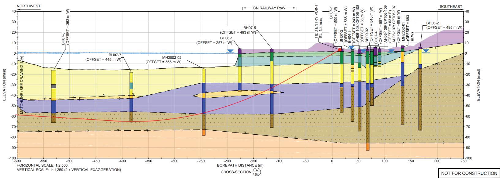
Both instream and terrestrial seismic surveys and electrical resistivity tomography (ERT) surveys, oriented roughly perpendicular to the HDD, were used to extrapolate geological conditions from the third-party boreholes to the selected TMEP crossing (Figures 6 and 7). In 2017, BGC monitored the drilling of an additional four boreholes along the proposed HDD alignment. Two boreholes were situated within the Fraser River, one borehole was on the south shore of the river (approximately 90 m north of the HDD entry) and one borehole was on the north shore (approximately 50 m north of the HDD exit). The target depth for the in-stream boreholes were -80 m elevation.
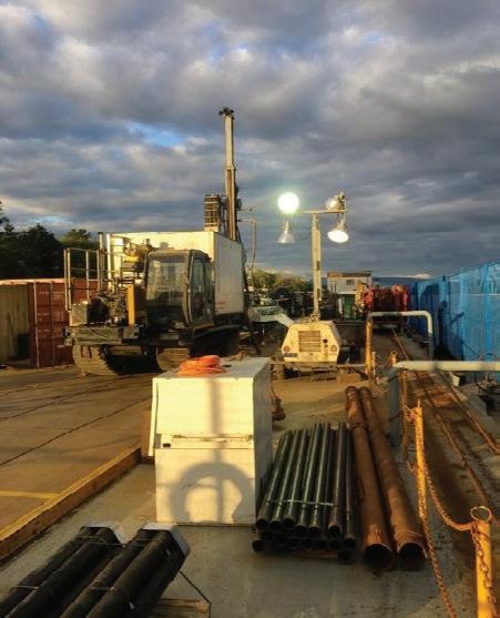
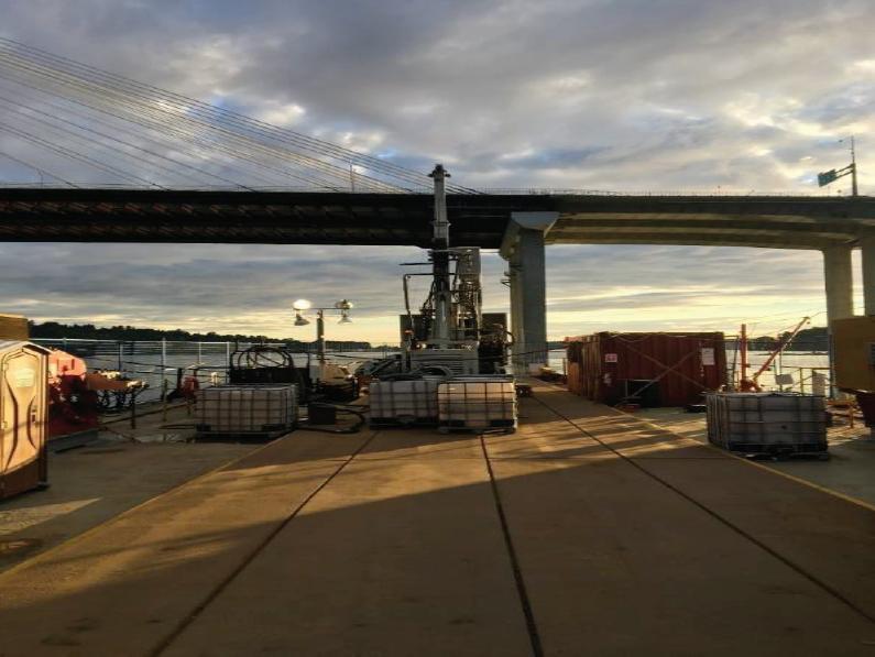
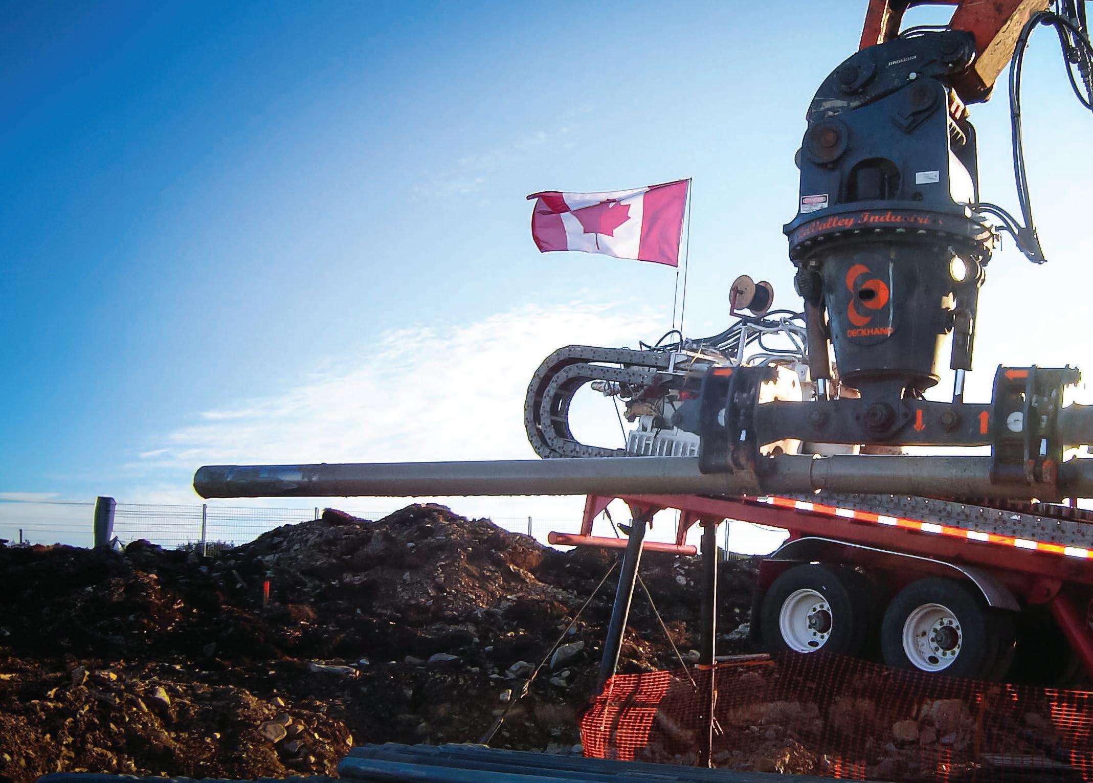
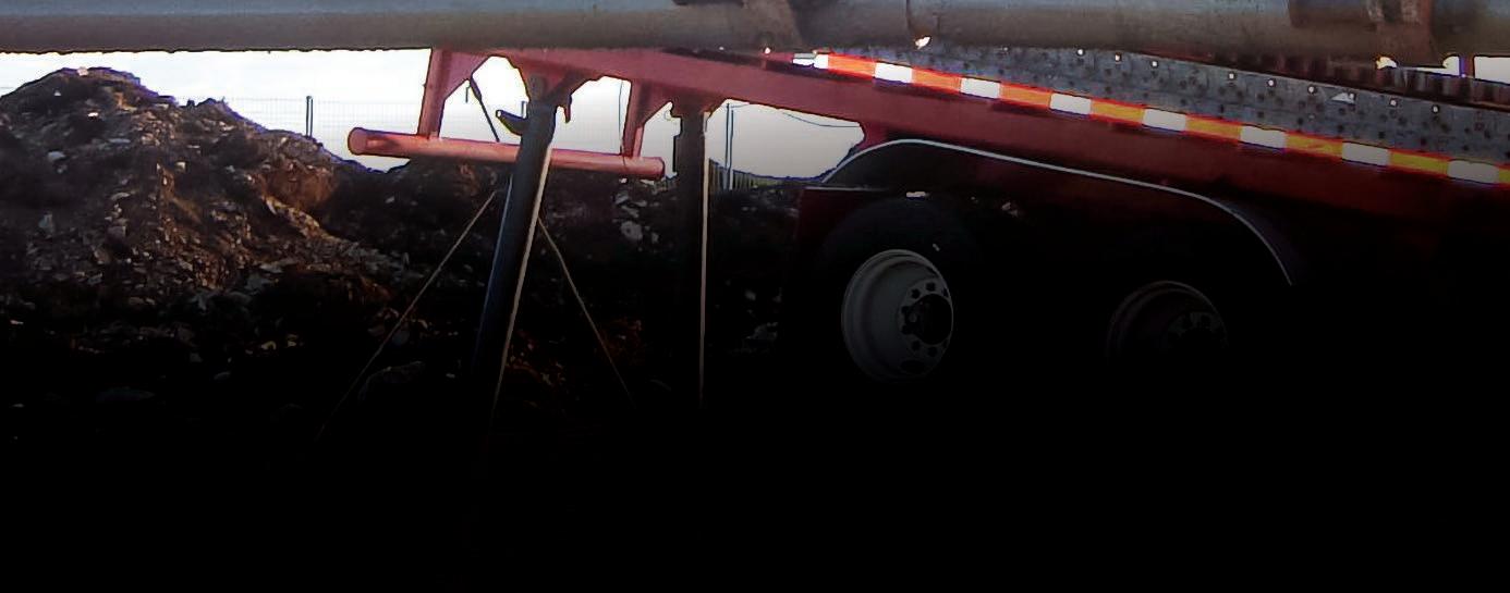
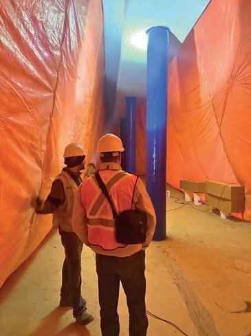
These target depths were selected to allow for flexibility in HDD alignment design; the boreholes targeted approximately 10 m below the maximum depth of the deepest HDD borepath under consideration at that time. The barge set up is shown in Figures 2 and 3. The drill rig was a track rig capable of drilling to the depths required. Permitting for the geotechnical boreholes within the area also proved to be challenging, owing to the sheer number of stakeholders involved for seemingly simple access requests. The borehole on the south side of the Fraser took over a year to obtain permit approval when a roadway maintenance contractor raised concerns about insurance indemnification; the Project eventually found it quicker to pursue an alternative access route through a railway yard.
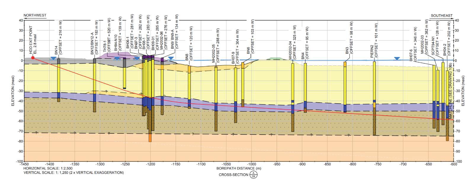
The primary geological units identified by the third-party boreholes and crossing specific drilling and geophysics were as follows (from youngest to oldest deposits):
• FILL (purple) – well graded gravel with some sand and trace silt. This unit consists of anthropogenic material placed during construction of nearby rail or road infrastructure on both sides of the river.
• OVERBANK AND BOG DEPOSITS (green) – peat and silt with woody and coarse fibrous organics identified on the south bank of the river.
Based on the literature review and investigations, the primary geotechnical considerations for the HDD crossing were:
• Artesian groundwater conditions observed within the Pre-Vashon sediments
• Possible cobbles and boulders within the Vashon till and Pre-Vashon sediments
• Presence of high-plasticity, sensitive glaciomarine clay and silt, within the Capilano Sediments, and related steering and/or borepath stability.
• Borehole stability within the very loose to dense Fraser River deltaic sand.
• Crossing below the Mary Hill Bypass Highway and the CN Thornton Yard.
• Seismic stability of the south river bank. Previous crossings of the Fraser River by other utilities were constructed in the upper Fraser River sands. This made sense as the deeper Vashon and Pre-Vashon sediments would represent far more challenging drilling as well as being unnecessarily deep. Therefore, knowing the separation between the lower glaciated sediments and the upper fluvial sediments was very important. As one would expect, geotechnical drilling was very challenging in the section of the HDD that was under the river. In the end, two boreholes were drilled in the river. Along with all the previous investigations this gave a good understanding of the depth and thickness of the Fraser River fluvial sand.
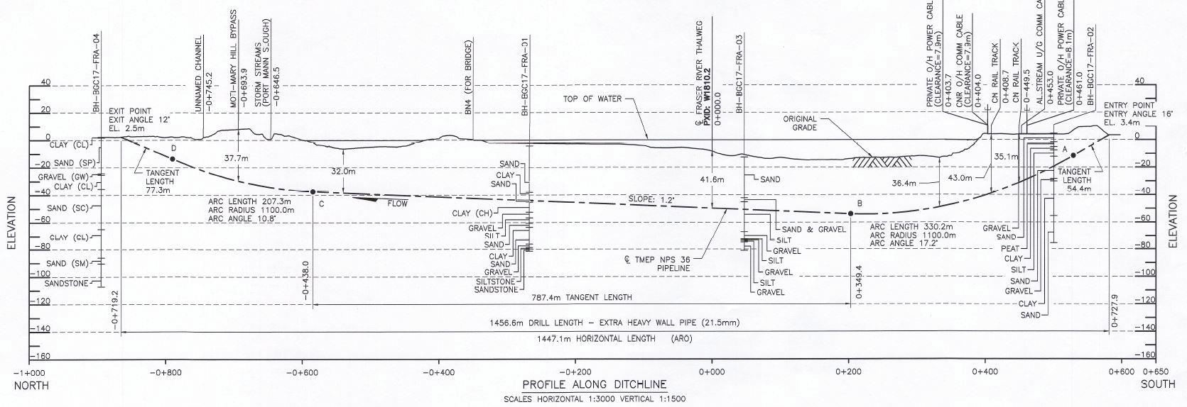
As one can see in the geological profile, the bottom of the gravel layer rises up to the north end of the crossing. As a result, the design profile rises up at a minimal slope to the north (Figure 6).
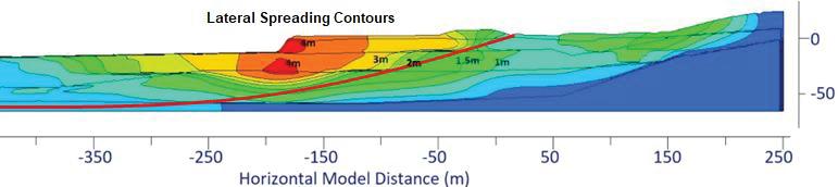
As the river was deepest on the south side and the entry needed to be deeper to be below the seismic hazard zone (due to seismic lateral spreading issues), the deepest point in the river mostly coincides with the deepest point in the
HDD profile. The entry point on the south side is just south of a berm. The original entry angle was 16 degrees but ended up closer to 18 degrees to ensure that the profile had the best chance to be below the potential lateral spreading zone (Figure 7). The exit point on the north side was set back from the Maryhill Bypass, one of the major arterial highway routes within the Lower Mainland connecting multiple municipalities and the Port Mann Bridge, and well back from the river. Lateral spreading did not influence the design drill profile on the north side as the profile of the HDD placed the entrance far enough behind the potential failing banks to not exceed the design stresses of the HDD pipe.
The design team thoroughly investigated a deeper profile in the harder Vashon and Pre-Vashon till material, however this would have been a far more challenging profile to drill. A deeper profile introduced the risk of much harder material, the chance of gravel layers (loss zones), artesian conditions and an expected high number of cobbles and boulders to challenge the steering. From a drilling standpoint the sands were a better and more homogeneous zone for drilling and there was previous good experience for installations within the Fraser River deposits.
From the early stages of the Project routing, it was known that the Fraser River crossing needed to be trenchless due to the size of the river. UPI had prepared a list of the 11 highest risk trenchless crossings (nine HDDs and two Direct Pipes). The Fraser River was considered the highest risk crossing for the project. This was due to a number of reasons:
• Historically the HDD crossings at this location have been challenging.
• Relatively long crossing.
• HDD profile encountered Fraser River fluvial sand which is susceptible to collapse during pipe pull or installation.
• HDD crosses below critical infrastructure, including a highway (Mary Hill Bypass) and railway tracks (CN Thornton Yard).
• Seismic design required a challenging profile.
• This was considered to be the keystone crossing of the Project, a high-profile crossing with no other trenchless options available.
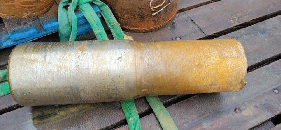
The drill entry was the south side and the exit side was on the north. The pilot hole started and immediately had challenges, due to the upper zone of very soft silts and clays with Standard Penetration Test (SPT) blow counts of zero. With this type of material, multiple tripping along the profile is not feasible as the material becomes disturbed and loses strength, and extracting the drill bit and trying to follow the same bore would not be possible. As a result, the contractor inserted a wash-over casing to approximately 65 m. This ensured that the bore through the soft upper zone would not be lost. Next the pilot bore encountered very hard zones, inferred to be cobbles and boulders in the Vashon glacial till sediments. This made it challenging to steer and the first pilot attempt resulted in a destroyed Tungsten Carbide Insert (TCI) tricone bit due to the hard material. Figure 10 shows the multiple attempts at a successful pilot hole. Ultimately, after multiple attempts and profile revisions the pilot was successful, however it required continuous monitoring by the engineering staff. This included being available at night during pilot hole operations.
The pilot hole for the first, unsuccessful crossing attempt was completed on November 3, 2021. The pilot hole was successfully intersected from the north side and completed with a single drill string pushed out to the north and reaming progressed from north to south.
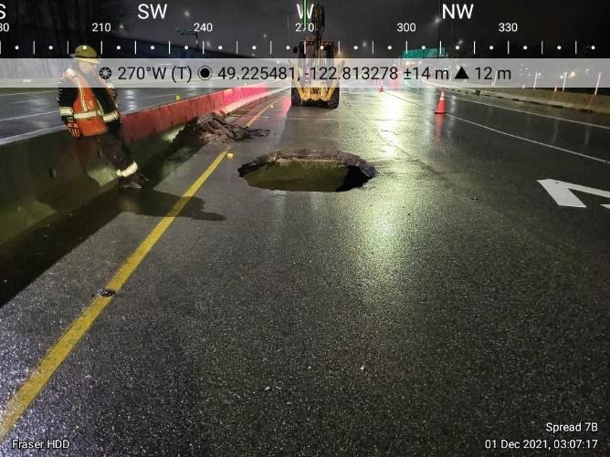
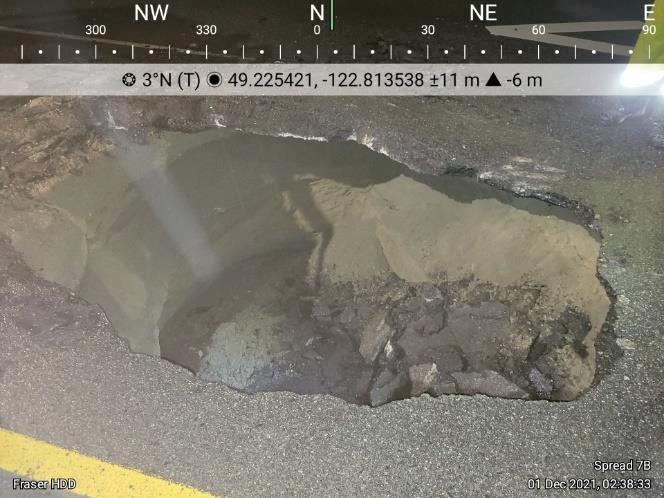
The first reaming pass which enlarged the hole to 762 mm (30-inch) was started November 8 but was stopped on November 16 (with only 868 m completed). A 1,372 mm (54-inch) reaming pass was then started. It was determined by the construction team that the larger final ream pass would provide a higher probability of a successful installation than the standard 48-inch ream for the NPS 36 pipe. The 1,372 mm (54-inch) reaming pass was completed across the entire crossing length (1,450 m) on November 19. A swab pass using 1,219 mm (48-inch) reaming tools was completed November 24. Product pipe pullback from the receiving pit started on November 25, but was stopped the next day due to mechanical failure of the HDD drill string. The first of several sinkholes appeared at the ground surface on and near Mary Hill Bypass on November 25. The partially installed product pipe was extracted from the hole by November 29, 2021.
During the reaming of the original profile, deep sinkholes began developing right up to the pavement of the highway, as seen in Figures 8 and 9. As this was a very busy highway, it required constant day and night monitoring by BGC and the project team. The embankment for the highway was constructed using sand fill material which is susceptible to the development of sinkholes. Repair of the sinkholes and ensuring safety of the travelling public was a priority for Trans Mountain and the entire TMEP team. Ground Penetrating Radar (GPR) was used to confirm the integrity of the highway and where necessary, immediate repairs were conducted each night.
For the original unsuccessful installation, the drag section was originally laid out in two pieces due to land issues, one very long section and a shorter section under 100 m in length. The pipe was pulled in about 150 m and the second section was welded on. Unfortunately, after the weld was completed, the pipe was now stuck likely due to the bore collapsing as a result of the sinkholes developing and the time delay in completing the weld. As the driller increased the pullback force in an attempt to get the pullback string moving again, the drill string snapped.
The crossing entered a prolonged shutdown from November 29, 2021, until August 10, 2022. During this time, new plans were devised to complete the crossing. Since the pilot hole on the south half of the crossing was such a challenge to complete successfully, a new alignment from the north side needed to be selected which utilized this section of
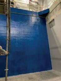
previously reamed bore. Numerous options were considered with the successful option shifting the alignment below Mary Hill Bypass 5 m eastward, and the exit point of the HDD at the receiving pit was shifted 100 m southward and within 50 m of the road crossing. This adjustment required the acquisition of additional temporary workspace and permanent easement. The new crossing design included surface casing at the entry side (original exit side) to encase the HDD borehole where it crossed below Mary Hill Bypass, to reduce the potential for circulating drilling fluids to overcut the native material and cause voids that could propagate to the road surface, the likely cause for the sinkholes observed during attempt number one. In addition, it was determined that it would be best to leave the 54-inch (137.2 cm) casing in place permanently while removing the 72 and 60-inch (182.9 cm and 152.4 cm) casings which ensured that the permanent casing would extend below the highway with a length of about 130 m, providing long-term support to the highway. This required special considerations for corrosion protection for the NPS 36 product pipe as well as the casing. It was decided to wrap certain sections of the casings and the product pipe in Scarguard, which would provide a positive separation of the casings and the product pipe.
Attempt number two began August 10, 2022. Over the period of August 19 to October 18, 2022, three telescoped surface casings were installed from the receiving pit under Mary Hill Bypass. As one can imagine, it was going to be difficult to successfully intersect a large reamed hole with a new pilot hole section drilled from the north side. This was particularly challenging when considering that the new pilot hole could only begin steering after traveling through the cleaned-out casing and there was a limited length available to accurately perform an intersect with the previously reamed 54-inch hole. In addition to this, the casing dropped somewhat during installation, which increased the slope and called for additional steering to correct for it. The pilot bore for attempt number two was completed over the period of October 25 to October 31, 2022, and the contractor was successful in intersecting the previously reamed hole at approximately 330 m from the exit side as the new design required. Following the pilot, a 1,219 mm (48-inch) reaming pass and a 1,118 mm (44-inch) swabbing pass were completed over the period of November 7 to November 20, 2022. The pullback of the 914 mm (36-inch) product pipe was completed over the period of November 21 to November 26, 2022. With the reduction
in length of the crossing due to the move of the receiving pit towards the highway, the product pipe could now be laid out in one section. This eliminated the need for the weld and the related time delay during installation. After the product pipe installation was successfully completed, BGC continued post-construction monitoring of the crossing until August 24, 2023. During and after attempt number two, several more sinkholes appeared in the surface of Mary Hill Bypass. The mainline contractor for this pipe spread responded to these ground deformations by completing several phases of road restoration that were monitored by BGC. Regular (daily to twice weekly) survey monitoring and GPR geophysical surveys were continued by BGC during post-construction to assess the long-term impacts to the road from these restorations and to assess if more ground deformations were likely to be observed.
A comprehensive post-construction GPR investigation was completed by BGC between May 30 and June 2, 2023 and an array of CPT probes were conducted between November 25 and December 1, 2024 with the goal of proactively identifying soft/loose zones of sediment potentially related to voids and sinkholes caused by the original attempt number one HDD installation.
Like all successful projects, teamwork is essential. In this case, the owner (TMEP), owner’s pipeline engineer (UPI), owner’s geotechnical engineer (BGC), HDD contractor (Michels), pipeline contractor (Kiewit Ledcor Partnership or KLPT), BC Highways (MOTI), and Canadian Energy Regulator (CER) worked together to ensure that this Project could be completed. The Fraser River HDD was the highest risk crossing on the Project. A second attempt was necessary to complete the crossing installation. This HDD required continual monitoring from the engineering design team. Extensive use of
telescoped large diameter casing was needed on the second attempt to prevent sinkholes from developing primarily under the highway. A second new drill pipe string was required to provide additional security against another drill pipe failure. A few of the efforts that were employed to try to minimize the risk to the crossing were:
1. Leverage prior experience from other utility installations.
2. The use of previous information from the 2004 HDD crossing replacement by TMPL.
3. Risk workshops prior to the start of construction to identify and make risk informed decision making.
4. Detailed risk workshops were held with the full Project team to identify and mitigate the anticipated risks.
5. Teamwork and communication.
6. The mainline contractor, the HDD contractor, TMEP construction personnel, the geotechnical engineers (BGC), and the pipeline and trenchless engineers (UPI) were in constant communication during the crossing construction.
Baumgard, A., Savigny, W., Cocciolo, P., (2004). Post Installation Geotechnical Issues Associated with Large Scale HDD Crossing, International Pipeline Conference (IPC), Proceeding of the IPC 2004, Calgary, Alberta.
Khare, M., Brown, R., Kochatt, B., Murphy, J., (2022) Trans Mountain Corporation Overcomes Numerous Challenges to Construct the Trans Mountain Expansion Project, ASCE Conference, Indianapolis, IN, USA.
Murphy, J., Zhao, J., (2021), Trans Mountain Employs Extensive Risk Mitigation Measures for Trenchless Construction on their new Pipeline Expansion, ASCE UESI Pipelines 2021 Conference, ‘Virtual Delivery’, Calgary, Alberta


AUGUR BORING
Michels Canada


Associated Engineering
CIPP TUBE
ASSET MANAGEMENT
MuddRuckers, Inc.


CONRETE LEVELLING
Associated Engineering
IVIS, Inc.
Associated Engineering


Associated Engineering
DEWATERING
Michels Canada


Insituform Technologies Limited
CONDITION ASSESSMENT


When making purchasing decisions about products and services in the trenchless technology industry throughout Manitoba, Saskatchewan, Alberta, and beyond, please support the companies whose advertising makes the NW Trenchless Journal possible. You will find them quickly with our convenient, easy-to-use Buyers’ Guide.
On the following pages, you will find information that will help you meet your purchasing requirements throughout the year ahead. The initial section of this Guide lists categories of products and services along with the various companies that can provide them to you. The following section provides an alphabetical listing of those companies, as well as the contact information you will need to reach them.
DIRECTIONAL DRILLING, RIGS, FLUIDS AND ACCESSORIES
IPEX, Inc.
LaValley Industries
Michels Canada
ENGINEERING DEISGN
Associated Engineering
EPOXY
Michels Canada
TCI Technologies, Inc.
FLOW MONITORING
IVIS, Inc.
CONSTRUCTION MANAGEMENT
DATA COLLECTION SYSTEMS
GENERAL CONSULTING
Associated Engineering
IVIS, Inc.
GROUTING
Michels Canada
HORIZONTAL IRECTIONAL BORING
Brandt Tractor
Michels Canada
HYDRO EXCAVATORS
Brandt Tractor
IVIS, Inc.
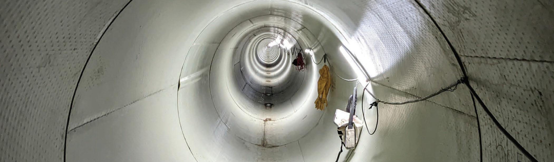
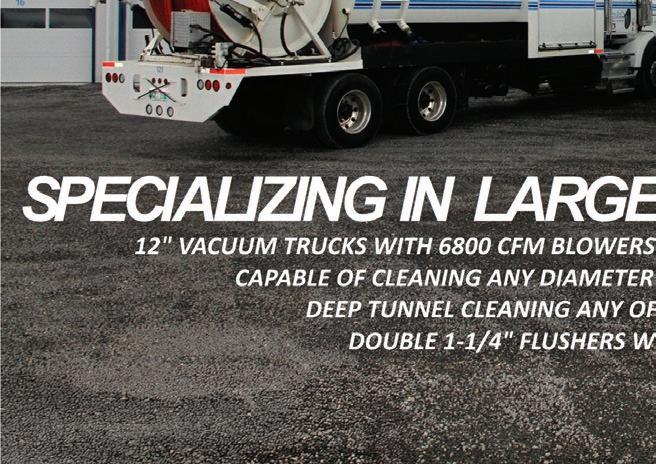
Uni-Jet Industrial Pipe Services
JETTERS
IVIS, Inc.
LATERAL REHAB
IVIS, Inc.
IPEX, Inc.
MANHOLE REHAB
Insituform Technologies Limited
IPEX, Inc.
IVIS, Inc.
Michels Canada
TCI Technologies, Inc.
MICROTUNNELING, SYSTEMS AND EQUIPMENT
IPEX, Inc.
Michels Canada
MUD SYSTEMS
MuddRuckers, Inc.
PIERCING RODS AND PUSHERS
Brandt Tractor
PIPE BURSTING AND SPLITTING
IVIS, Inc.
Michels Canada
PIPE CLEANING
Canadian Induracoat Corporation IVIS, Inc.
Uni-Jet Industrial Pipe Services
PIPE FITTINGS
IPEX, Inc.
PIPE FUSION
Michels Canada
PIPE HANDLING EQUIPMENT
LaValley Industries
PIPE INSPECTION
Canadian Induracoat Corporation IVIS, Inc.
PIPE JACKING
Michels Canada
PIPE RAMMING
Michels Canada
PIPE RELINING
Canadian Induracoat Corporation
Insituform Technologies Limited
IPEX, Inc.
IVIS, Inc.
Michels Canada
TCI Technologies, Inc.
PIPELINE INSPECTION AND EVALUATION
Associated Engineering
Canadian Induracoat Corporation
IPEX, Inc.
IVIS, Inc.
Michels Canada
ROCK DRILLING
Michels Canada
SEWER – PRESSURE AND VACUUM
Insituform Technologies Limited
IVIS, Inc.
Uni-Jet Industrial Pipe Services

SLIPLING
Michels Canada
SOIL STABILIZATION
MuddRuckers, Inc.
SPOT REPAIR AND POINT REPAIR
IVIS, Inc.
Michels Canada
TCI Technologies, Inc.
TRENCHING
Brandt Tractor
Michels Canada
TUNNEL – LARGE DIAMETER
Michels Canada
UTILITY LOCATING
Brandt Tractor
IVIS, Inc.
VACUUM EXCAVATING AND EXCAVATORS
Brandt Tractor
VIDEO INSPECTION


LISTINGS BY COMPANY NAME
ASSOCIATED ENGINEERING
Jason Lueke
780-451-7666 luekej@ae.com www.ae.com

BRANDT TRACTOR
888-227-2638
sales@brandt.ca www.brandt.ca
CANADIAN INDURACOAT CORPORATION
Doug Ritch
250-652-0812
d.ritch@induracoat.com www.induracoat.com

INSITUFORM TECHNOLOGIES LIMITED
Andrew Foster 888-982-4717 afoster@aegion.com www.insituform.com
IPEX, INC.
Wendy Huynh
289-881-0120 wendy.huynh@ipexna.com www.ipexna.com
IVIS, INC.
Dolores Eaton
780-476-2626
marketing@ivisinc.com www.ivisinc.com


LAVALLEY INDUSTRIES
Craig Larson 218-444-3030
craig@lavalleyindustries.com www.lavalleyindustries.com


MICHELS CANADA
Mike Ireland
780-955-2120
mikeireland@michelscanada.com www.michelscanada.com


MUDDRUCKERS, INC.
204-992-6833
info@muddruckers.ca www.muddruckers.ca
Ken Auty 411-409-2211 kauty@tcicarbonfibre.com www.tcicarbonfibre.com
UNI-JET INDUSTRIAL PIPE LTD.
Scott Culum 204-633-4879 www.unijet.ca


TCI CARBON FIBRE TECHNOLOGIES


Elliott Swarthout
VP of Operations, Vector Magnetics, Ithaca, New York
Mary Neher, PE
Bennett Trenchless Engineering, Folsom, California
Jed Sheckler
Director of Marketing, Vector Magnetics, Ithaca, New York
Bobby Cloud
President, DrillGuide, Brookshire, Texas
The Intersect Method in HDD intentionally guides an intersection of two pilot bores before reaming and pulling product. The main reasons for using the Intersect Method are drilling where fluid pressure control and elevated risk of inadvertent releases are a concern; the near-surface geotechnical conditions at both the entry and exit require conductor casings; drilling length exceeds the torque/pullback limits of available rigs; and drilling with a limited time window for completion. The first successful HDD intersect occurred in 2001 under the River Tees, England using a Guidance Coil to overcome geotechnical conditions. In the subsequent quarter of a century the Intersect
Method has evolved into an umbrella term that encompasses four main techniques: Magnetic Intersect which includes both Passive Magnetic Intersect and Active Magnetic Intersect under a Guidance Coil; Radar Intersect; and Direct Gyro to Gyro Intersect. Due to the risk of accumulating positional errors over the length of the two bores Direct Gyro to Gyro intersects generally use either Radar or Magnetic Intersect as a fallback plan.
This article describes the various rationales for using the Intersect Method, how each Intersect Method works, and presents two case studies: A 9,842 ft (2,999.84 m) intersect using Passive
annular space exceeds the capability of the surrounding ground to contain it. This is referred to as a hydrofracture. The drilling fluid then travels along the induced fracture out of the annular space. If the drilling fluid reaches the ground surface, which does not always occur depending on the path of least resistance and volume of fluid lost, it can have environmental and social impacts. For example, although the drilling fluid is generally composed primarily of water and non-toxic bentonite clay it can increase turbidity in a water body or create a mess and traffic nuisance in a roadway.

Magnetic Intersect to overcome geotechnical conditions for the Port of Santos in Brazil and a 13,213 ft (4,027.32 m) active magnetic intersect under the Ganges River, India mitigate IDFR risk and overcome rig torque and pullback limits.
There are multiple reasons why the Intersect Method might be chosen over the typical single pilot bore approach to an HDD crossing. In the authors’ experience, one of the most common driving factors is drilling fluid pressure control/mitigation of the risk of hydrofracture (sometimes referred to as a frac-out, inadvertent drilling fluid
release (IDFR), or inadvertent release (IR)). This article will use the term IDFR. Other reasons to perform an intersect include challenging near-surface geotechnical conditions where conductor casings are required at both entry and exit (which may or may not be tied to IDFR risk), mitigating a lack of torque/pumping capacity of the available drill rig due to the length of the crossing, and needing to shorten the duration of the schedule. Drilling fluid is one of the critical components of the HDD method. The typically bentonitebased fluid serves several essential purposes including aiding in excavation of the soil, carrying the cuttings from the bit back to the drill rig, providing hydrostatic support to the otherwise unsupported borehole, and cooling and lubricating the drill pipe and tooling during drilling. Without drilling fluid, the installation method is not HDD. However, since the drilling fluid returns from the bit to the ground surface through the annular space between the drill pipe and soil, which is not supported by anything beyond its own strength and the drilling fluid, there is always a possibility for drilling fluid to escape the bore. There are many ways that an inadvertent release of drilling fluid can happen including through very high permeability granular soils, existing or induced fissures in clay, fractures in rock, or along man-made objects like piles or pipelines. The specific type of IDFR that the HDD industry spends a great deal of time analyzing and mitigating the risk of is when the pressure of the drilling fluid inside the
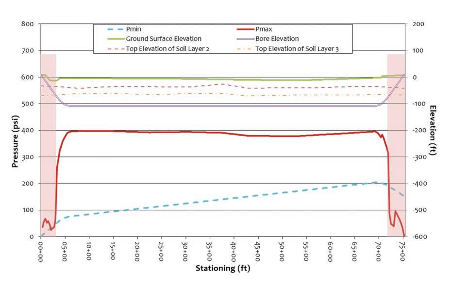
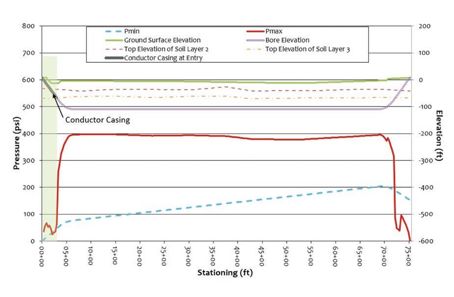
The risk of hydrofracture can be analyzed and mitigated in several ways during the design process. Specification of the Intersect Method during design often occurs due to the results of a hydrofracture risk evaluation. A hydrofracture risk evaluation consists of an estimate of the maximum capacities of the ground and minimum required drilling fluid pressures at many points along the bore. An example of the results of this evaluation are shown in Figure 1. Figure 1 is a plot of the ground surface and bore profile in feet of elevation (upper portion of the graph, right hand y-axis) and the maximum allowable pressure and minimum required pressure in psi (lower portion of the graph, left hand y-axis), against horizontal stationing on the x-axis. If the minimum required drilling fluid pressure is too close to or exceeds the estimated maximum formation pressure, as it does on both ends of the bore shown in Figure 1, mitigation should be incorporated into the design.
Design mitigation measures include modifying the bore geometry and/or specifying specialized construction measures. There are several ways to modify bore geometry to lower the risk of hydrofracture that depend on ground conditions. Generally, the most straightforward method is to increase the crossing depth at the location where risk is elevated. Increasing the depth of the crossing
results in more overburden pressure which increases the amount of annular pressure that the soil can confine. Deepening the crossing profile may have the benefit of increasing the soil strength or getting into more favorable material for drilling. Deepening the profile in rock may allow for drilling in a less weathered, more competent formation.
Increasing the crossing depth can be achieved by increasing entry/exit tangent length(s), increasing vertical bend radii, increasing the entry/exit angle(s), setting the entry/exit further back, or some combination of these options. Selecting steeper entry/ exit angle(s) allows the profile to traverse a challenging geotechnical zone more quickly and achieve adequate cover more quickly. This approach can be beneficial if the elevated risk of hydrofracture is, for example, due to a steep riverbank where ground covers decrease quickly before the bore can achieve sufficient depth. Choosing larger vertical radii can achieve greater maximum depth, though it will take more horizontal distance to get there. This can be beneficial when the elevated risk zone is far enough from the entry/exit that the increased horizontal distance is not a problem. Larger vertical radii also allow more flexibility in steering and keep pipe stress low during pullback. Finally, changing the entry/exit location so that it’s further from the feature of interest or higher-risk zone allows for maximum depth to be achieved before reaching the high-risk zone of the crossing.
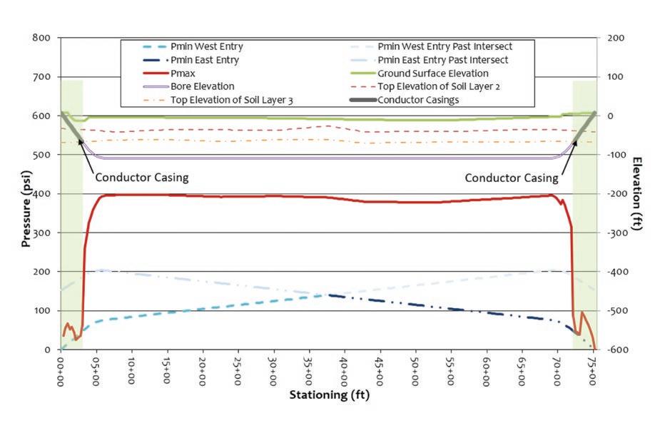
If modifying the geometry is not feasible or not sufficient on its own, there are two effective approaches that can be specified during construction. The first is to use steel conductor casing at the entry point. Conductor casing is generally not installed at the exit point of a standard HDD crossing. Conductor casing is steel pipe, of sufficient diameter to allow the largest reamer to pass through with room to spare. It can be hammered (the most common approach) or drilled into place and provides a stable conduit for the tooling and drilling fluid. One of the primary reasons to use conductor casing is to allow the bore to pass through challenging ground conditions such as poorly graded gravel, significant cobbles/boulders, very soft to soft clays, and/or very loose to loose sands. Conductor casing can also be helpful for large diameter or long crossings to mitigate the risk of over-excavation or nearsurface collapse when tooling is coming in and out of the ground many times. Figure 2 shows the same crossing as Figure 1, but with the area stabilized by a conductor casing at the entry point highlighted in green.
The second approach is to specify the Intersect Method. Of the options discussed
so far, the Intersect Method is the only design approach that reduces the minimum required pressure for the drilling fluid to return to the rig. The other options all focus on increasing the estimated maximum capacity of the geotechnical formation by designing the bore with more ground cover or in better ground. The Intersect Method involves completing the pilot bore by drilling simultaneously with two rigs located at opposite ends of the crossing. Normal, single rig reaming, pullback, and installation procedures can then be followed to complete the installation. By breaking the pilot bore into two separate reaches the required drilling fluid pressure to complete the pilot bore is reduced by up to approximately 50% (depending on where in the crossing the intersect is made). This substantially reduces the risk of hydrofracture and allows construction of longer bores. The Intersect Method also allows conductor casing to be installed at both ends of the bore to further reduce hydrofracture risks at the ends of the bore and promote better circulation of drilling fluids. Figure 3 shows the same example hydrofracture risk evaluation using the Intersect Method and conductor casings on both sides.
The Intersect Method can also be used to overcome two construction challenges: lack of rig/pump capacity during the pilot bore and construction schedule constraints. Having a rig drill from each side of the crossing effectively cuts the crossing length in half. Therefore, two smaller rigs that would not have enough torque, thrust, or drilling fluid pumping capacity to complete the entire pilot on their own can be used simultaneously during pilot drilling. If the hole diameter needs to be enlarged to allow for installation of the product pipe and the single rigs were already near capacity, a larger rig may be mobilized on one side for reaming, conditioning and pullback. Using two rigs for a single crossing can also have significant schedule benefits. Drilling the pilot bore from both sides allows it to be completed in less time. Having a second rig on site and available to provide tension on the tail string (the portion of drill pipe on the opposite side of the tooling from the primary HDD rig) can also have a beneficial impact on reaming production rates depending on the length of the bore and ground conditions.
There are four types of intersects in HDD: Passive Magnetic Intersect, Active Magnetic Intersect, Radar Intersect, and Direct Gyro to Gyro Intersect. Each intersect method has pros and cons which should be assessed. The main difference between methods is how actual measurements between the two bores are made. Commonalities include two drill rigs which operate from opposite sides of the shot with one side designated as the steering side and the other side as the target. There is generally an approach phase as each rig aligns and drills toward an intersect zone. Intersects often use a combination of steering and locating tools contained within the steering assembly. Selection of the steering assembly is best left to experienced steering hands. Few intersects are done directly end on. Instead, most are steered into the existing target borehole with a low incidence angle. Given there is an ellipse of uncertainty around every borehole position regardless of guidance method used, most intersects plan for a ‘zone of intersection.’ This is the acceptable range of Measured Distance (MD) from each drill rig for the intersection to occur. This intersection zone allows operational flexibility to adjust for how well aligned the bores are upon entering this zone, how drilling conditions are influencing steerability, and how rig performance is affecting drilling.
In the approach phase, the target bore is steered to the intended intersect depth using one or more HDD guidance methods. The opposite side is also steered close to the intersect depth using one or more
guidance methods. During the Intersect phase of operations, measurements are made to determine the relative positions of the bores, and the steering side is steered toward the target bore. In most operations, measurement between bores and subsequent steering happens several times to achieve an intersect. Throughout the process, both rigs monitor vibration and borehole and annular pressures to determine if the bores are close to communicating. In all methods, when an intersect is imminent, the target side Bottom Hole Assembly (BHA) is pulled back far enough so the two bores can be connected without damaging equipment in either BHA. To be successful, all intersects require careful planning and execution, and close communication between both rigs during operations.
Passive Magnetic Intersect uses the residual magnetic field of the target BHA as the magnetic target to steer towards. The other BHA contains a steering tool with magnetometers that measure the target magnetic field. During the approach phase, the two bores are drilled to positions where they overlap each other. Then the intersect phase begins. The steering side BHA remains stationary collecting data, while the target BHA is either pushed or pulled past the stationary steering tool. Analysis of the magnetic field from magnetic dipole at the end of the target BHA determines the distance and direction from the steering tool to the magnetic pole, as in Figure 4.
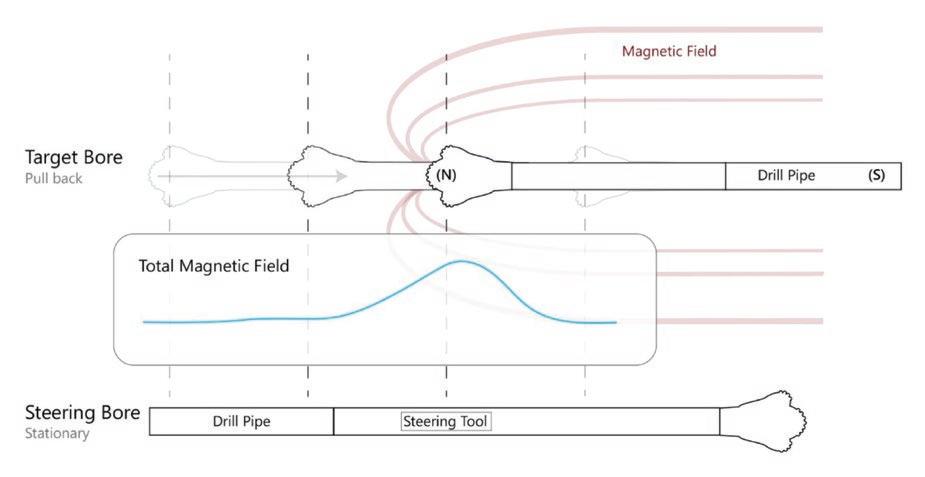
The steering side bore is then drilled ahead toward the target bore. If there is no communication, the process is repeated until the two bores are physically connected.
Passive Magnetic Intersect in HDD remains popular because it requires no specialized equipment to generate or detect the magnetic signal, nor does it require surface access at the intersect point. The main challenge is matching coordinate systems between the two pilot bores because each bore is building its own survey starting from its own entry point. Passive Magnetic Intersect for HDD is based on the wellestablished Passive Magnetic Ranging (PMR) method used since 1970 in the oilfield. PMR remains one of the primary oil field methods of relief-well detection, planned well intersects, well avoidance, and well twinning. The PMR process was adapted to HDD in 2001, with hundreds of successful HDD intersects since then.
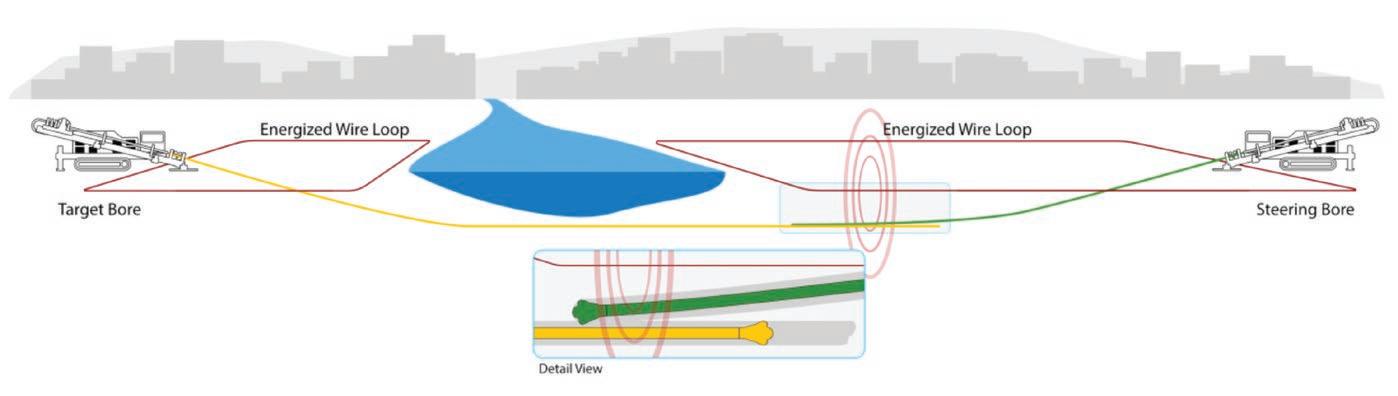
In Active Magnetic Intersect, a magnetic steering tool in each bore directly measures the distance and direction to an energized source (either AC or DC). In HDD, the energized source is most often a wire loop on the surface that is land-surveyed in position. The electrical current flowing on the wire creates a magnetic field along the wire with a known magnitude (AC or DC) and frequency (AC) as in Figure 5. The steering tool in each bore uses magnetic tracking by making repeated independent measurements to the same magnetic source. This keeps both bores on the same coordinate system and does not have the cumulative errors associated with all surveys.
Typically, the steering side is drilled towards target side until the two bores communicate. The main advantage to this method is both bores are on the same coordinate system, because they reference the same magnetic source which has been surveyed in location on the surface. The main challenge to using this method is the need for surface access at the intersect point to lay out the surface coil. This may be mitigated by designing a bore profile that places the intersect zone below one of the energized wire loops on the surface.
The first successful Active Magnetic Intersect in HDD occurred in 2001 under the Maas River, Netherlands by Prime Horizontal using a ParaTrack Guidance Coil. Geotechnical conditions required conductor casing to be run on both sides of the bore. There have been hundreds of successful Active Magnetic Intersects since then.
Radar Intersect is a proprietary name. It uses a Radar module behind a gyroscopic module on each BHA. This system follows the same process as Passive Magnetic Intersect with the bores drilled to a point where they overlap. Measurements are taken when the two Radar Modules are at their minimum separation. Analysis provides the X, Y, and Z distances between the two radars. The drilling contractor and surveyors then determine which bore will drill forward and be steered toward the other.
Advantages to this method include both bores are on the same coordinate system, and surface access at the intersect point is not required. The main challenge is the need for
a set of gyro modules and radar modules on each side of the operation.
Radar Intersect was first used successfully in 2013 with hundreds of successful intersects since. For a case study see the 2022 NASTT Project of the Year – North Bakken Expansion – Lake Sakakawea HDD.
The accuracy of gyroscopic tools available for HDD make direct gyro to gyro intersects possible. This method requires running a gyro survey tool on each side of the pilot bore. Each bore builds an independent gyro survey without direct measurement to either a passive or active magnetic source. Due to the nature of survey errors, each survey will have a growing ellipse of uncertainty around the actual bit location the further each drill advances. Given this positional uncertainty resulting from both surveys, passive magnetic intersect or radar intersect are almost always planned as a contingency in case the intersect cannot be accomplished directly gyro to gyro. Advantages to this method include surface access at the intersect point is not required, intersect specific hardware is not required, and the added operational cost of taking data for passive magnetic intersect or radar intersect is avoided. The main drawbacks are the need to match coordinate systems between the two bores because each bore is building an independent gyroscopic survey and the associated cost of running two separate gyro tools. The first successful Direct Gyro to Gyro intersect in HDD occurred in 2013. Since then, there have been hundreds of successful Direct Gyro to Gyro intersects.
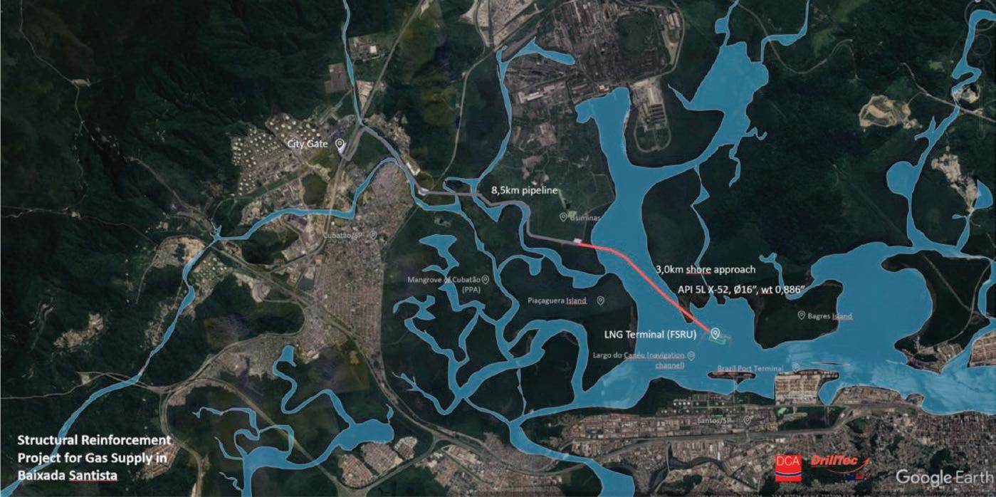
The Structural Reinforcement Project for gas supply at the Port of Santos LNG Terminal in Baixada Santista includes the implementation and operation of a maritime terminal for receiving, storing, and re-gasifying Liquified Natural Gas (LNG) and a pipeline to transport it to The City Gate Receiving Station in Cubatão, state of São Paulo, Brazil. The pipeline extends 10 miles (16 kms) along Santos Estuary and passes through the Cubatão mangroves to reach The City Gate, see Figure 6. In Brazil, mangroves are generally classified as a Permanent Preservation Areas due to their ecological importance. Mangroves protect biodiversity as nurseries for various aquatic and avian species and protect water quality by stabilizing river and estuary banks, and act as natural barriers against floods.
The LNG Terminal, designed to accommodate Floating Storage Regasification Unit-type ships is in the navigation channel of the Port of Santos. To reach the LNG Terminal the pipeline had to cross 9,842 ft (3,000 m) of estuary and river. The offshore location of the LNG Terminal and ecosystem sensitivity severely limited available job site
locations. An HDD was planned with two curves required with combined radii and deviations exceeding 30 degrees. The initial strategy was to divide the crossing into two sections, with an intermediate location where the two sections would meet and be tied in.
This approach was discarded by the client’s request to construct a single directional bore to mitigate the risks of potential channel dredging and the impossibility of direct intervention on the channel bed for tie-in. A second strategy was a conventional full length HDD crossing. This was also discarded due to the following:
1. Geotechnical data showed the hydraulic pressure required to clear cuttings would likely cause IDFR.
2. The force and torque required would pose a substantial risk to the structural capacity of the drillpipe.
3. Difficulty in maintaining tool orientation required for precise steering.
DrillCon identified a shore approach using an HDD intersect as the next best option. An intersect zone in a tangent section of the bore needed to be identified based on the operational capabilities of the drilling rigs, geotechnical surveys, minimum cover requirements, and hydraulic pressures. A plan was developed to drill 80% of the
bore at approximately 260 ft (79.2 m) deep in geologically homogenous gneissic rock formation with a compression strength of ~ 90 MPa. A 150 ft (46 m) long intersect zone was identified approximately 3,280 ft (999.7 m) from the shore approach exit point. The drill bit selection followed IADC guidelines, with an HDX 12-1/4 in HDS-TCI ultra- premium, IADC 627 (HDX 40) selected for rock drilling and an MT IADC 135 type bit for soil. The reamer selected for rock sections was an Inrock HDX 37 – TCI rock reamer with a 26-inch OD, equipped with a blade centralizer of 12-1/4 inch and five sealed bearing cutters, while for soil sections, a fly cutter and hybrid reamer were chosen.
Other components of the BHA included a bent sub for soil excavation, a mud motor for rock drilling, non-magnetic drill collars for the guidance equipment, and a Pressure While Drilling system, which paired with a BHA designed to generate low annular pressure, assisted in preventing formation damage.
The complexities of the planned bore required a highly accurate guidance system to align the bores before the intersect zone. The ParaTrack Gyro was selected because
surface conditions precluded the use of a surface tracking system and it has the proven durability to tolerate the extremely challenging hard rock conditions. Being a gyrocompass tool, it did not require an active magnetic field for accurate guidance. Positional uncertainty of the approaching bores was minimized by using a Gyro in each bore. This in turn minimized the required alignment correction before the intersection of the 12-inch pilot bores. The first Passive Magnetic data analysis indicated that the two boreholes were separated by 9 ft (2.7 m) vertically (<1 ft/1000) and 3 ft (.9 m) laterally (<0.3 ft/1000). Drilling advanced, with Passive Magnetic Intersect providing steering correction until a successful intersection occurred at 6,562 ft (2,000 m) MD from onshore side, 3,280 ft (999.7 m) MD from barge side.
Drilling conditions significantly slowed the project timeline. The gneissic formation as drilled had a compressive strength of ~ 250 MPa not the expected 90 MPa. The onshore jobsite was equipped with a Herrenknecht model H275 HK 300T rig with a maximum pull force of 660,000 lbs (299,370.96 kgs).
This rig completed over 6,500 ft (1981 m) of pilot hole and performed final reaming up to 26 in (.66 m) for over 8,200 ft (208.3 m).
The second rig was a Prime Drilling PD100-50RP-L with 225,000 lbs (102,058.3 kgs) of pull force. This rig was installed on a barge specially designed to accommodate the rig and other HDD equipment. Positioned near the future maritime terminal, this rig completed approximately 3,280 ft (999.7 m) of pilot hole and assisted with column torque during the 26 in reaming phase, rotating to the right to reduce torsion on both the drilling column and the Herrenknecht drilling rig. For the final reaming phase, DrillTec employed a larger Herrenknecht H200-HK 500T rig with 1.1 million lbs (498,951.6 kgs) of pull force and over 100,000 ft/lbs (13,825.5 kg/m) of torque. This rig completed the reaming of the 26 in and pulled the final 16-inch (.4 m) conduit.
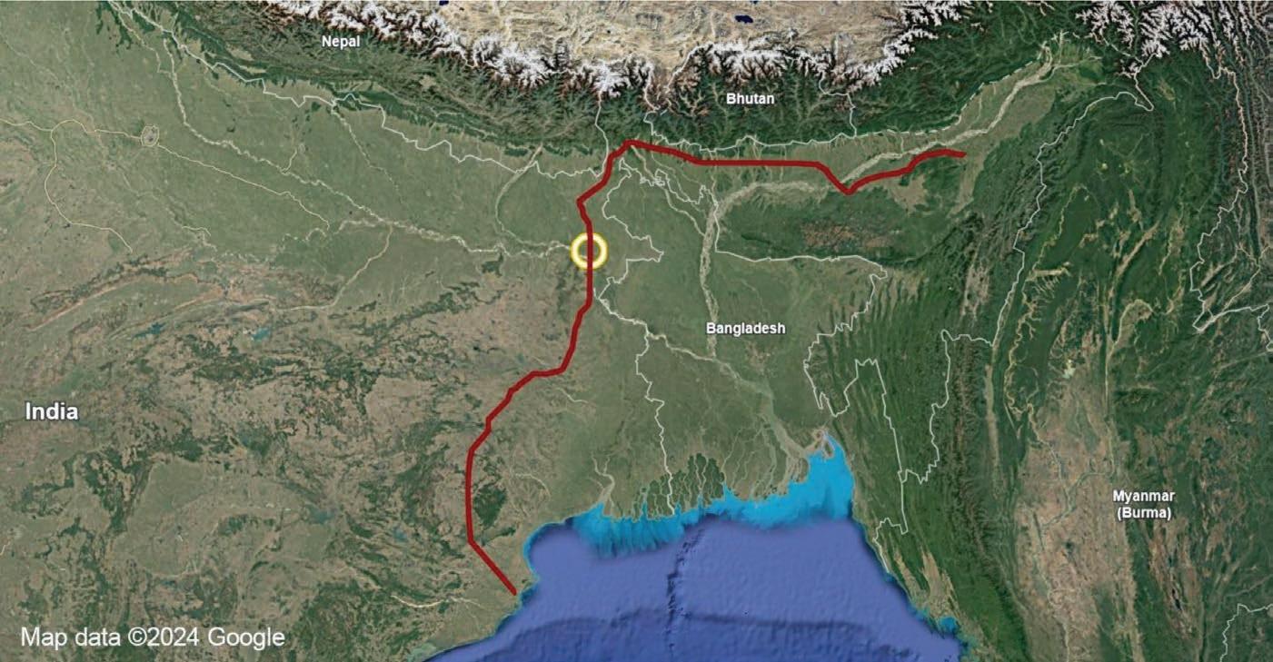
The Paradip Numaligarh Crude Pipeline (PNCPL) is a 1,047-mile (1,685 km) crude oil pipeline that will run north then east from Paradip Port on the eastern coast of India to termination at the Numaligarh
refinery in Assam, India, see Figure 7. When completed the PNCPL will expand refinery capacity from 3.0 million tons per annum to 9.0 million tons per annum as part of the Numaligarh Refinery Expansion Project (NREP). The route crosses all major rivers in Eastern India, with the Ganges crossing the longest at 13,213 ft (4,027.3 m). The Ganges River flows across the foreland basin known as the Indo-Gangetic Plain and has highly seasonal flow rates governed by the Southwestern Monsoon.
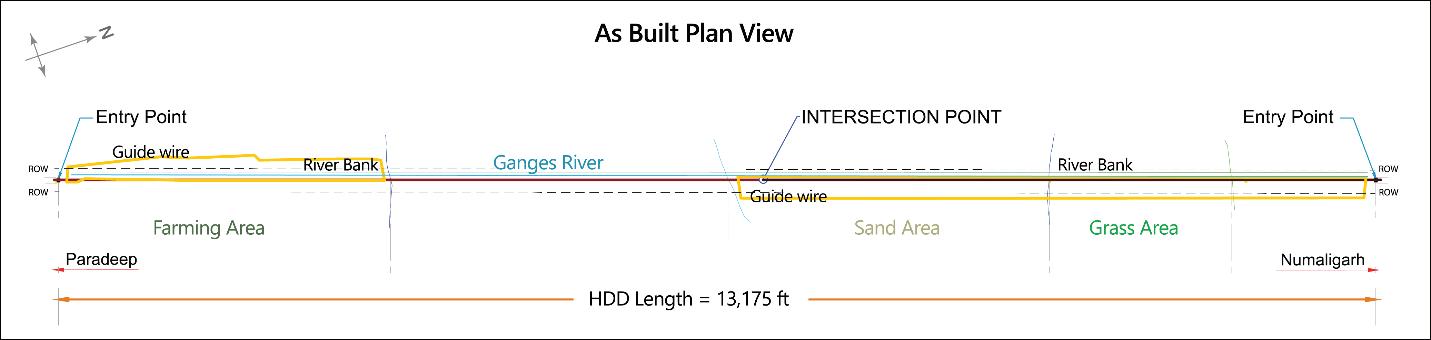
For this crossing, M/S Trenchless Engineering Services was tasked with installing two parallel pipelines within a 59 ft (18 m) right-of-way. The main pipeline is 26-inch (.7 m) steel. A parallel 6-inch (15.2 cm) accessory line was installed with 20 ft (6.1 m) of separation. The 12-inch (30.5 cm) pilot bore was reamed in three stages to 20-inch, 30-inch, and 38-inch (50.1 cm, 76.2 cm, and 96.5 cm) for the final pass. The accessory line was drilled with 12-inch (30.5 cm) pilot bore and not reamed. The 13,213 ft (4,027.3 m) length of the HDD crossing necessitated an intersect because no HDD rig on the market had the required power to overcome the modelled friction and drag. Drilling an intersect
also lowered required flow rates for hole cleaning and stability and kept fluid pressure well below modelled IDFR pressures. The planned intersect point was approximately midway, which effectively reduced drilling length by 50% for each rig. Other benefits of intersecting at the midpoint included:
1. Increased drilling accuracy and control because each drill path was 6,600 ft (2,011.7 m) rather than if it was drilled as a single shot of 13,213 ft (4,027.3 m).
2. Reduced risk of excessive torque, drag, and pipe sticking than if drilled as a single shot.
3. Improved fluids control and management than if drilled as a single shot because adjustments could be made from each rig should problems occur.
A ParaTrack magnetic steering tool and P2 active magnetic guide wires were selected for guidance. This combination provided the accuracy required to perform the intersections, while ensuring that the two bores were drilled parallel and within the right of way along their entire length. The designed intersect zone was just after crossing the Ganges River. Operations were scheduled during the dry season to avoid seasonal high-water flows which on average double the width of the river. This permitted a P2 AC magnetic guide wire to be installed across the seasonal flood plain.
The energized guide wire generated a magnetic signal used to continuously measure the positions of the pilot bores. Repeated independent measurements of locations kept positional uncertainty to less than 3 ft (.9 m) both vertically and laterally at the intersect length of 6,660 ft (2,011.7 m) (<0.5 ft/1000). The extremely soft mixed clay formation allowed for
rapid drilling progress. Active Magnetic Intersect allowed for continuous positional measurement in near real-time, without the wait times associated with other Intersect methods, ensuring that drilling was never hindered by the guidance process.
Trenchless Engineering Services employed two American Augers DD1100 rigs, each with over 1 million lbs of push/pull capacity on opposite sides of the river. Each BHA was fitted with ParaTrack Pressure Modules to provide real-time annular and drill pipe pressure monitoring. After successful intersection at 6,660 ft (2,011.7 m), the first 12-inch pilot was reamed in three stages to 20 in, 30 in, and 38 in for the final pass. To ensure that cutting flow could be maintained over nearly 2 miles (3.2 km), the team designed special reamers for dual-sided pumping. Two 600 GPM (3,270.6 m3/day) pumps were operated in tandem for reaming, achieving a flowrate of nearly 800 GPM (4,360.8 m3/day). This limited torque to less than 60,000 ft/lbs (8,295.3 kg/m) and helped install the 26 in pipeline in just 76 days. Completion of the parallel six in accessory line was completed using the same techniques in just ten additional days including pilot drilling, welding and pullback.
Worldwide demand for HDD is growing as energy transmission and distribution is increasingly placed underground. Intersects are a proven technique that expand the possibilities in HDD. The multiple technologies and methods encompassed in The Intersect Method provide options and flexibility to meet the unique challenges of individual projects. Planning and experience
are the two most important factors in assuring a successful project. While intersects add additional pieces and players, the added complexity is easily managed through good planning and communication. Involving rig operators and steering engineers in the design and planning phase of an intersect project is a proven way to head-off problems and misunderstandings before they occur. Bringing in those who will be executing the plan at an early stage helps ensure that the plan is feasible and realistic. Intersects can be complicated and raise stress levels of all involved. After nearly 25 years and thousands of successful intersects completed worldwide, intersects in HDD are no longer unusual. The good news is there are many engineering companies, rig operators, and steering engineers with direct experience in intersects. If you are facing HDD intersect on a project, talk with these experienced professionals. Experience matters when success is critical.
Bruist, E. H. (1972). A New Approach in Relief Well Drilling. Society of Petroleum Engineers, publication # 003511. ISCWSA Well Intercept Sub-Committee. (2019). Well Intercept Sub-Committee eBook. ISCWSA. University of Highlands and Islands.
Jameison, A., et al. (2017). Introduction to Wellbore Positioning, ebook v9-10-2017. ISCWSA. University of Highlands and Islands.
Teer, J., Winkler, T. (2001). Drilling the Maas River from Both Sides, Directional Driller Magazine, December 2001.
Walstrom, J. E., et al. (1969). An Analysis of Uncertainty in Directional Surveying, Society of Petroleum Engineers, publication # 002181.

The NW Trenchless Journal is made possible by the companies below who convey their important messages on our pages. We thank them for their support of NASTT-NW and its publication and encourage you to contact them when making your purchasing decisions. To make it easier to contact these companies, we have included the page number of their advertisement, their phone number, and, where applicable, their website.


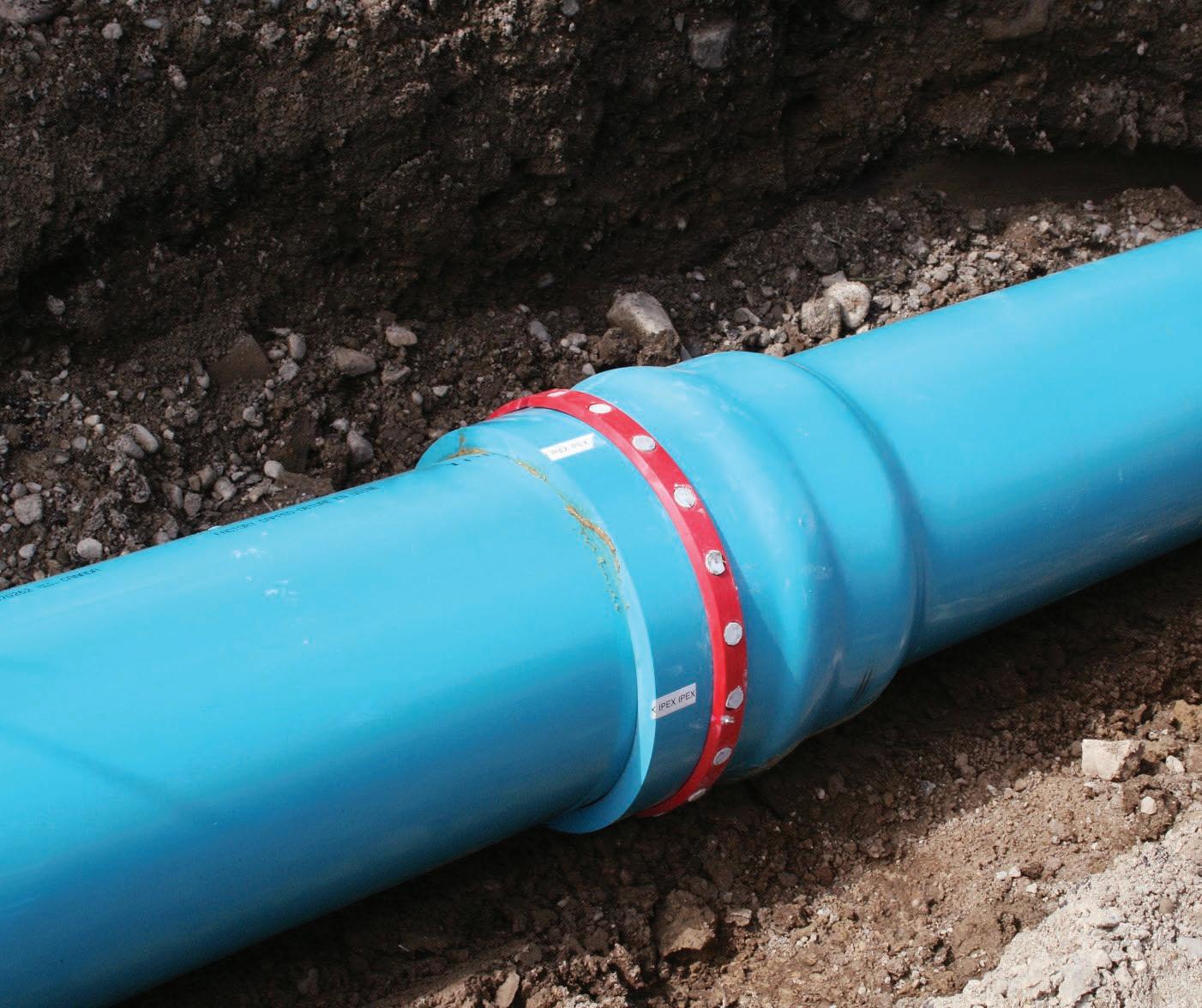
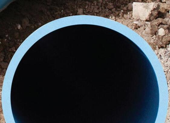
Engineered for Horizontal Directional Drilling (HDD) and other trenchless applications, TerraBrute® CR is a 100% non-metallic, AWWA C900 PVC pressure pipe system. Non-corroding and installation-friendly, TerraBrute lets you standardize on PVC throughout your municipal water infrastructure. Designed for large diameter projects up to 24 inches, it offers unmatched strength and leak-free performance in high-pressure environments, ensuring efficient, cost-effective solutions with minimal disruption.