
Navigating the Complexities of Trenchless Cable Installations


October 27-29 | Vancouver Convention Centre
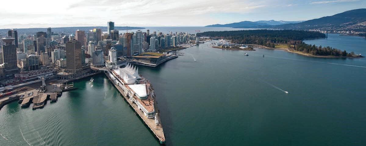
No-Dig North is the premier annual conference focused on trenchless technology in Canada. Attendees include engineers, contractors, manufacturers, and municipal representatives who seek to learn about and discuss sustainable, cost-effective solutions for infrastructure needs. The 2025 No-Dig North and ISTT International No-Dig conference is coming to Vancouver, BC at the Vancouver Convention Centre, October 27-29, 2025. Learn more at

No-Dig North is owned by the North American Society for Trenchless Technology (NASTT), a not-for-profit educational and technical society established in 1990 to promote trenchless technology for the public benefit. For more information about NASTT, visit our website at nastt.org.
Happy 30th Anniversary to us! The NW Chapter is celebrating our 30th year of involvement with NASTT.
In 1995, Rick Prentice, P.Eng. (at the time with Reid Crowther), and also a member of the NASTT Board, started communicating with Edmonton area individuals who had interest in pipe rehabilitation technologies. He approached Ken Chua, P.Eng. (City of Edmonton, Drainage Department) and secured support and buy-in to engage in bringing knowledge and techniques to the City and the region. Edmonton Drainage had developed a solid tunnelling group that delivered many projects in Edmonton through the 2020s.
Ken Foster (Insituform Technologies Limited), Dave Krywiak (Stantec Consultants), Chris Skowronski (Associated Engineering), Bruce Campbell (Neptune Coring) and Reg Belyea (Insituform Technologies Limited) were among the first core group to share the vision for a local Chapter. These individuals represented some of the early consulting firms and contractors involved in trenchless technologies. Sam Ariaratnam (University of Alberta) was also a key contributor, and was able to provide connections to NASTT and its Board through his trenchless research and projects.
The core group, representing the Edmonton region, took the initiative to reach out to like-minded entities in British Columbia and Washington state in 1996. In 1997, the NW Chapter was officially chartered, including Alberta, British Columbia and Washington. The first Executive and Board members were:
Chair – Ken Silvester (BC)
Vice Chair – Ken Chua (AB)
Secretary – Sam Ariaratnam (AB)
Treasurer – Dave Otto (BC)
Directors –
Dave Krywiak (AB)
Ken Fender (WA)
John Jurgens (WA)
David O’Sullivan (BC)
Michael Kirby (WA)
In the early years, the key areas of activity were Edmonton, Vancouver and Seattle.
By 2002, the Chapter had over 80 members and was hosting a variety of activities including an Alberta Trenchless Conference starting in 1997, demonstration projects and presentations, and trenchless related courses.
In 2005, the BC members moved to establish the British Columbia Chapter, and in 2009 the Pacific Northwest Chapter was established.
These moves promoted more localized opportunities and reduced the Chapters’ geographical areas. The NW Chapter currently represents Saskatchewan and Manitoba.
The Chapter places a high value on providing education and exposure to trenchless technologies. In 2002, a Conference, or Symposium, alternating annually between Edmonton and Calgary was undertaken. Since 2004, these conferences included NASTT developed short courses. The Alberta Conferences were at times held jointly with the Tunneling Association of Alberta and the Canadian Society for Civil Engineering. The symposiums were very successful and increased in attendance, presentations and tradeshows. In 2017 NASTT in conjunction with the Alberta group transformed the annual symposium into the first No-Dig North, held in Calgary. No-Dig North continues as an annual event, rotating between Calgary, Toronto area, Edmonton and Vancouver.
COVID put a damper on No-Dig North, resulting in cancellation in 2020, with rejuvenation in 2021. The conference continues to grow with a new attendance record essentially every year. The 2025 No-Dig North conference will be held in Vancouver, in conjunction with the Annual ISTT conference. In 2026, the conference will return to Calgary.
The majority of the current approximately 180 chapter members are in Alberta, with most in Calgary and Edmonton. Currently there are two NW student Chapters: University of Alberta and Red River College in Winnipeg. The Calgary section took the initiative and held the first Alberta Symposium since 2016 this year. It will be an annual event in Alberta, alternating with Edmonton.
The Edmonton and Calgary sections have hosted technical luncheons, generally between September and April, and are continuing to do so. RRC has hosted technical presentations and short courses and is working to expand the offerings. The current NW Board is committed to involving more trenchless practitioners, academics and students in Saskatoon, Regina, Winnipeg and other centers.
The NW Chapter 2025 AGM will be held at No-Dig North. Two Board positions are vacant, and will be filled prior to the AGM. If you are attending No-Dig North, please come to the AGM. The Chapter will be handing out limited edition 30-year Anniversary pins (see mock up, pictured right). And as always, please consider volunteering for the Chapter or local sections. It’s a great way to learn more about the industry and meet others with similar interests.


As Chair of the NASTT Board of Directors, I want to take a moment to thank you for your continued commitment to the trenchless industry and your active engagement within your regional community. Our success as a society depends on the strength of our Regional Chapters, and the Northwest region continues to lead by example.
One of the most inspiring aspects of our organization is the dedication of our volunteers. Whether you’re serving on a committee, mentoring a young professional, organizing local events, or simply showing up to lend a hand at chapter activities, your time and energy are what make this society thrive. Your expertise, generosity, and passion for trenchless technology are the heartbeat of our mission, and I want to express my deep appreciation for everything you do.
“On behalf of the entire Board of Directors, thank you for being a valued member of the Northwest region and the larger NASTT family.”
While our regional events are essential to strengthening local networks, NASTT also provides you with opportunities to engage with trenchless leaders on a global scale. First up is the 2025 No-Dig North & ISTT International No-Dig, taking place in Vancouver, British Columbia, October 27–29. This combined conference will bring together trenchless professionals from around the world, offering a unique platform to showcase North American innovation alongside global advancements. It’s a rare and valuable chance to learn from

international peers and share the outstanding work being done across our region.
Then, in 2026, we’ll head to Palm Springs, California for the NASTT 2026 No-Dig Show, March 29 – April 2. Palm Springs promises to be an exciting and memorable destination, and our team is already hard at work planning a world-class event with technical sessions, networking opportunities, and the unmatched energy that makes the No-Dig Show such a cornerstone of our industry calendar. If you’ve ever considered presenting, volunteering, or exhibiting at a national level, now is the perfect time to start planning for your involvement.
These events, local, national, and international, are only made possible by the engagement and leadership of members like you. As we grow and expand our impact, I encourage you to consider how you might get involved in the months ahead. Whether it’s submitting a paper, nominating a deserving peer for an award, supporting student and young professional programming, or participating in one of our many outreach initiatives, your voice matters and your presence makes a difference.
On behalf of the entire Board of Directors, thank you for being a valued member of the Northwest region and the larger NASTT family. Your contributions help move our industry forward, one innovative, trenchless step at a time. I hope you’ll join us in Vancouver this fall or Palm Springs soon after!
APPLICATION DEADLINE: NOVEMBER 1

The NASTT No-Dig Show Municipal & Public Utility Scholarship awards employees of North American municipalities, government agencies and utility owners who have limited or no training funds with a Full Conference and Exhibition registration to the NASTT No-Dig Show (oneday conference registrations are also available). Hotel accommodations for three nights at the host hotel are provided for selected applicants. Recipients have full access to all exhibits and technical paper sessions.


By Evan Murdzek, EIT, Burns & McDonnell Engineering, Inc., Wallingford, Connecticut

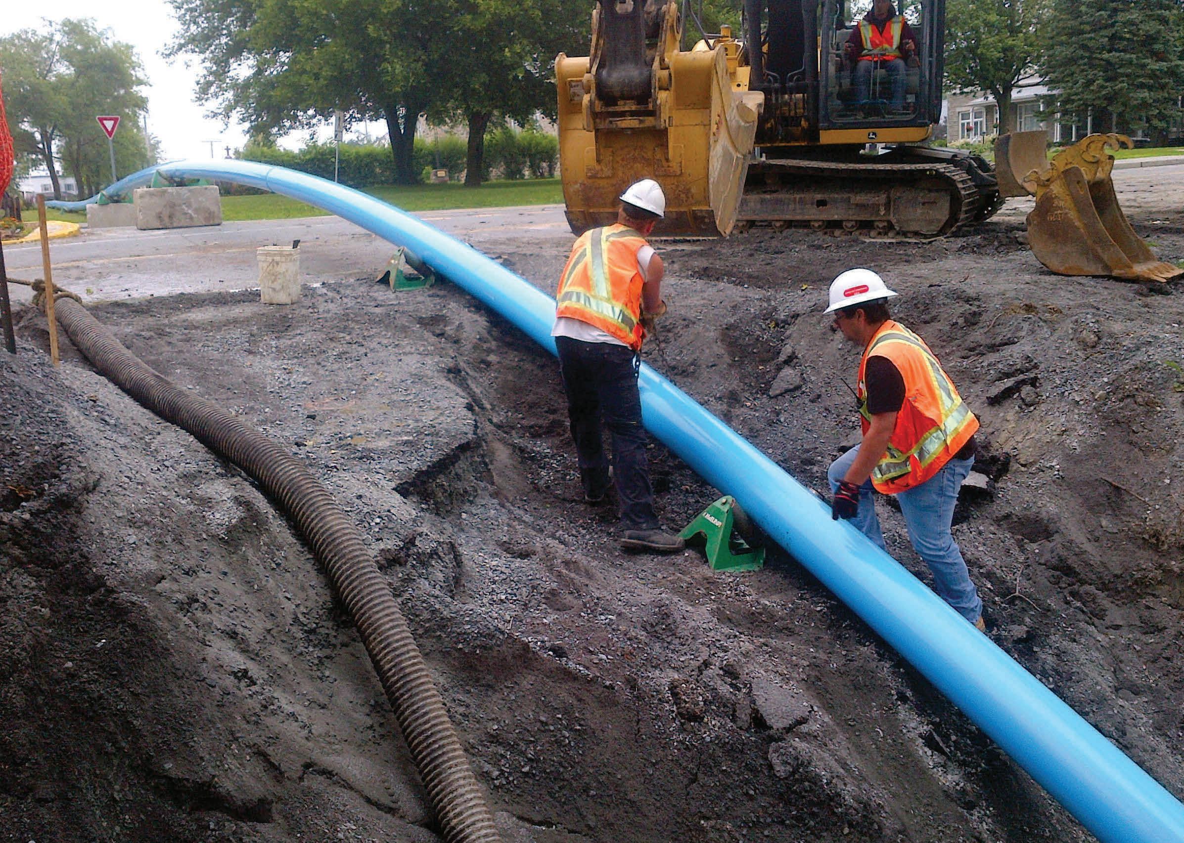
The increasing prevalence of underground cable installations in North America is driven by various factors, including high population density areas where overhead installations are infeasible, submarine transitions to underground from offshore wind farms, and the need for storm hardening in the face of increasingly frequent severe storms. Undergrounding any utility often leads to trenchless installations since it is rare that an alignment is available with no obstructions preventing open cut installations. Cable installations present unique design considerations that must be carefully evaluated. Trenchless installations that may be feasible for a water or gas installation may prove infeasible for cable systems due to the strict limits imposed by the electrical characteristics of the cables they house. This paper discusses how these electrical constraints, including material, length, depth, and parallel considerations, affect trenchless design and the logistical challenges that may impact the feasibility of trenchless designs. By identifying the root causes for the constraints imposed on trenchless installations by the nature of underground cable installations, trenchless designers can propose feasible designs that can mitigate the concerns of electrical utility owners.
When cables are in operation, electrical losses during transmission increase the temperature of the conductor. This heat has the potential to damage the cable insulation, which could then lead to a short circuit, which results in a loss of service from that circuit. A large portion of underground transmission design is mitigating that heat to keep it below the failure threshold of the insulation for the target electrical load to be carried
on that circuit. As an example, the most common insulation type currently used in underground transmission design is Cross Linked Polyethylene (XLPE) insulation, which starts to deteriorate above 90°C.
One of the simplest methods to dissipate this heat is using materials with low thermal resistivity that allow heat to conduct more easily through it. A typical trenchless installation for electrical cable consists of cables within electrically rated conduit, surrounded by a filler material within a casing. That filler material can have a large impact on the ability of the system to dissipate heat, since it typically makes up the largest volume of material that heat needs to be conducted through to dissipate away from the cable system. Therefore, a thermal grout is often used as the filler material in the borehole. This grout is specified to have a low thermal resistivity. Installation and testing of this grout introduces additional installation steps that often are not required on other non-electrical trenchless installations. The conduits and casings with relatively thin walls typically have a low impact in terms of heat conduction.
Conflicts during the process of thermal grout installation are commonly encountered on Horizontal Directional Drill (HDD) installations. Once the conduit bundle has been pulled into the bore hole, the design may necessitate replacing the bentonite slurry used to maintain borehole integrity with a thermal grout. This typically involves using a thermal grout that is denser than the bentonite that is used. Therefore, grout can be pumped into the low point of the bore at the same rate that bentonite is removed at grade. The lack of definitive methods to test whether the bentonite was fully replaced adds risk to the electrical cable
installation. Bentonite typically has a much higher thermal resistivity than the specifically engineered thermal grout, so any areas where large quantities remain in the borehole could overheat the cable insulation during operation and cause a fault.
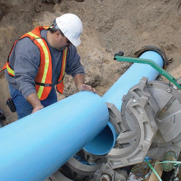
Most electrical transmission circuits are Alternating Current (AC) installations. When a conductor carrying AC power is encircled with a ferrous material like steel, a voltage is induced on that encircling material. This voltage causes that material to increase in temperature, which in turn increases the temperature of the cable system and impacts how well heat is dissipated away from it. Due to these considerations, nonferrous materials are often specified for electrical installations. Common nonferrous materials used include Centrifugal Cast Fiberglass Reinforced Polymer Mortar (CCFRPM), Fusible Polyvinyl Chloride (FPVC), and High-Density Polyethylene (HDPE). In the case of FPVC and HDPE conduits and casings, the inner bead of all
fusion joints also must be removed prior to installation. This is to prevent difficulties pulling in the conduit bundle into the casing, or the cable into the conduit respectively. This makes joining large segments of conduit together using a joint in the middle less favorable, as de-beading that final joint is very difficult.
In addition to the previously mentioned electrical considerations, there are mechanical considerations that limit how far a cable can be pulled in conduit before the cable becomes damaged from the tensile forces of the cable winch or the crushing forces pressing the cable into the sidewalls of the conduit. As the length of the pull increases, the total weight of cable within the conduit system increases. Thus, the total force of friction resisting cable pulling increases, which increases the overall tension on the cable. To mitigate these considerations, cable systems in North America typically utilize underground concrete splice vaults to break up cable pulling into smaller segments approximately 2000 feet (609 metres) long. This introduces another limitation on the total length of a trenchless installation. It cannot be so long that the cable cannot be pulled through conduits from the vault at one end of the installation to the vault on the other end. From the cable design perspective, this can be mitigated to a point with specialty lubricants applied to the cable during pulling operations to reduce the experienced coefficient of friction. From a trenchless design perspective, increasing the radius of bends and decreasing degrees of curvature can reduce the magnitude of forces the cable will experience during installation.
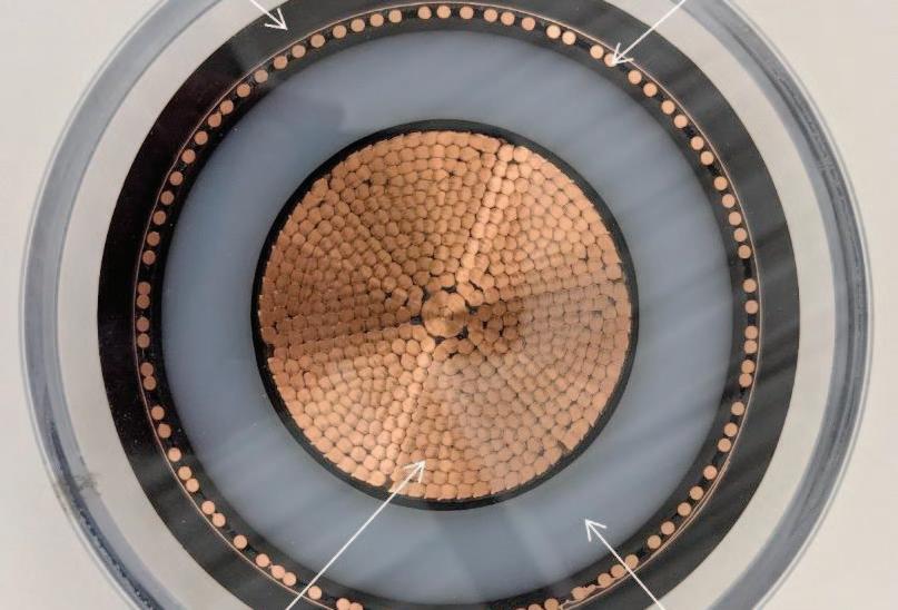
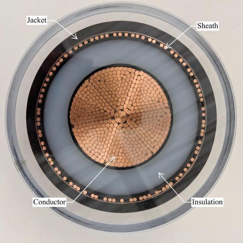
Length of trenchless installations also play a role in the dissipation of heat, albeit in a more indirect way. Underground cables are manufactured with a metallic sheath for cable protection, often in the form of concentric neutral wires, below the jacket and above the insulation layer.
Due to the alternating current on the conductor, a voltage is induced on the sheath. The simplest way to mitigate this sheath voltage is to ground it at each end of the cable (known as two-point bonding). This, however, creates a circuit, which means those concentric wires have a current and therefore increase in temperature. To avoid this, many transmission class cables in North America are only grounded at one
end (single point bonded), while the other end goes through a sheath voltage limiter (SVL), which creates an open circuit. Since this bonding configuration does not create a complete circuit, current does not flow and temperature does not increase. However, this creates a new constraint. As length increases, the maximum sheath voltage will increase. Limits are set for the maximum sheath voltage of cables on particular systems based on safety standards, guidance from professional societies, and the available standard cable designs from cable manufacturers. Typically, this limits the length in between sheath breaking splices to approximately 2000 feet. This is a significant reduction in maximum length of a trenchless installation, where horizontal directional drills can reach five times that length or further.
An alternative bonding technique that is less common in North America is cross bonding. This form of bonding requires three section lengths within 10% of length of each other and uses destructive interference to effectively cancel out the induced voltage on the sheath utilizing transposition of the sheaths for each phase. Destructive interference refers to the behavior of waveforms to cancel each other out. If two waves of equal magnitude that are 180 degrees out of phase of each other are overlaid, they will cancel out and there will
be no resulting wave. The same principle can be used to cancel out three waves of equal magnitude that are 120 degrees out of phase of each other. The magnitude of these AC waves are proportional to the standing sheath voltage, which is directly related to the total length of a segment. Continuous sheath cable splices can be used at splicing locations to create longer cable segments that are closer in length to a long trenchless installation. This is an option to make longer installations feasible, but are still subject to maximum length limits based on the cable construction and risk tolerance of the utility owner.
As depth increases, the effectiveness of heat dissipation decreases. This is due to the larger volume of native soil that heat must conduct through to get to open air. As part of underground transmission design, calculations are performed to determine how deep cables can be installed while still achieving required electrical and thermal ratings. This maximum depth in some cases can make a trenchless installation infeasible that otherwise would be technically feasible. Thermal resistivity testing of native soil during geotechnical investigations will help determine just how much of an impact additional native soil will make on the thermal ratings of an installation.
For trenchless installations requiring launching and receiving shafts, the depth of installation will also impact the ability of the duct bank to intercept the bore on each side geometrically. Cables have minimum bending radii determined by the cable manufacturer that must be followed when designing the intercept. Small radii, large degree bends also increase pulling tension and sidewall pressure, which further limits how tightly a duct bank can intercept a trenchless installation. The geometry of these bends lead to deep trenches for long horizontal distances, which may be challenging to install.
Parallel trenchless installations are often limited primarily by the precision of the installation method. For precise, well steerable methods, bore holes can be installed in close proximity with relatively low risk. For electrical installations however, that close proximity leads to mutual heating of the circuits. The distance between bores must be taken into consideration when performing heating calculations often leads to a wider spacing than would otherwise be needed
resulting in larger workspaces. In congested areas this may make an installation infeasible.
Often in particularly long installations, an intermediate jacking station (IJS) is utilized to more efficiently advance the installation pipe through the ground. These IJS's are typically made of metal, and therefore can increase in temperature during cable operations similarly to how a steel casing would. In order to be suitable for electrical installations, they must be designed to not form a closed loop around the cable system through the use of nonferrous material or spacers, or be designed to be removed after installation is complete, prior to energization.
As with any industry, work is being done to push the limits of what is possible for trenchless transmission installations. To pull further lengths, specialty lubrication and pulling methods are being developed and adopted by more of the industry. Relatedly, specialty cable designs with thicker jackets

Jason Lueke, P.Eng., Ph.D. National Discipline Leader, Trenchless Technologies
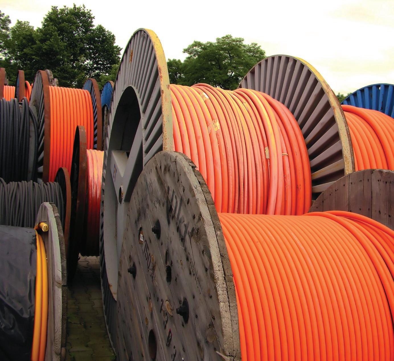
are possible to mitigate the risk of faults due to sheath voltage build up over these longer pulls. The larger cable reels needed to support these larger pulls can be delivered by ship to avoid road weight and height restrictions. Each project has its own unique challenges and risks associated with it, which also brings the potential for unique solutions. The key factor in proposing feasible designs is understanding why the design criteria exist as they do in order to develop holist ic solutions to accommodate those design criteria to suit a particular installation. With so many interconnected risks, a partnership between transmission designers and trenchless designers is needed to mitigate risks effectively.
CIGRE. (2020). Sheath bonding systems of AC transmission cables - design, testing, and maintenance.
IEEE. (2018). IEEE Guide for Thermal Resistivity Measurements of Soils and Backfill Materials.
IEEE. (2014). IEEE Guide for Bonding Shields and Sheaths of Single-Conductor Power Cables Rated 5 Kv through 500 Kv.

Siu Fung Ma, C.Eng., P.Eng., M.I.C.E Discipline Lead, Municipal Infrastructure Vancouver

Cian McDermott, P.Eng Manager, Pipelines & Trenchless Markham
Chris Lamont, P.Eng Discipline Lead, Trenchless Technologies Edmonton
Keith Kingsbury, P.Eng Technical Specialist, Pipe Rehabilitation Saskatoon
Craig Pass, P.L.(Eng.) Senior Infrastructure Engineer Calgary
Associated Engineering’s trenchless specialists bring experience in horizontal directional drilling, pipe bursting, utility tunneling, pipe jacking, pipe ramming, auger boring, microtunnelling, relining, and pilot-tube-guided boring to help find the appropriate solution for every project. Our wide range of trenchless services includes design, feasibility studies and review, condition assessment, buried asset management, value engineering and peer review, and risk and constructability assessment. Working with our clients and partners we help develop sustainable and resilient solutions for our communities.

By Tony Araujo, Paragon Systems Testing, Concord, ON, Canada and Chris Macey, P. Eng., AECOM, Winnipeg, MB, Canada

Introduction
Short-term flexural properties flexural modulus and flexural strength are key design parameters for CIPP (Araujo et al 2010). Unlike traditional pipe materials which arrive on a job site with their minimum physical and dimensional properties already established, the final physical properties and wall thickness of CIPP cannot be determined to the same degree of certainty until after the installation has been completed and the installation acceptance tested (Braun & Macey 2021). A feature of CIPP liners is the ability of the installer to choose from a myriad of resin/reinforcement systems, many of which are capable of achieving much greater physical properties than the minimums defined by the commonly used CIPP standard practices ASTM F1216 and F1743. Owner specifications commonly permit installers to utilize these higher properties to design thinner liners than would result if the liner was designed using only the ASTM minimum physical properties (Araujo & Yao, 2019). Research has shown that installed flexural properties and wall thickness of CIPP, not infrequently are less than specified (Macey & Zurek, 2012), (Pharand & Rancourt 2015), (Araujo & Yao 2019), (Allouche et al 2014), (Waniek et al 2020). This phenomenon is inherent in the installation process for CIPP heat cured liners and has been referred to as natural variation (Braun & Macey 2021). While earlier research has highlighted individual examples of this variation (Allouche et al 2014),
in these cases the number of samples which were tested as well as potential variations in sampling and testing protocols, precluded statistical analysis of this data and a broader conclusion about its prevalence across the industry.
To better understand the prevalence of this phenomenon, it is necessary to analyze physical properties of a much larger number of CIPP installations under conditions where field sampling, test specimen preparation and testing have been controlled using consistent protocols. Recently, research from large projects consisting of hundreds of samples meeting these requirements has been published (Pharand & Rancourt 2015), (Araujo & Yao 2019). Both of these examples from different jurisdictions demonstrate that when comprehensive well managed QA/QC processes are employed in projects with most or all CIPP installations sampled and tested, a relatively predictable proportion of CIPP pipes will exhibit issues with either flexural properties or wall thickness or both, which must then be addressed by the installer and/or contract administrator to ensure that the Owner receives design compliant CIPP. Paradoxically, a large majority of CIPP projects do not include any post installation physical testing of the installed liner.
To
Like any complex construction project many factors need to be considered and controlled to ensure that the final built
product meets the Owners requirements and CIPP rehabilitation is no exception. Unlike traditional ‘factory manufactured’ pipes, the field manufactured nature of CIPP increases the variability of the final installed product. The objectives of sewer rehabilitation using CIPP are defined in the NASTT CIPP Good Practices Guidelines as
• Arrest internal deterioration of the host pipe
• Stabilize the existing pipe-soil structure by arresting infiltration, the primary driver for most sewer degradation
• Support external groundwater pressure and where required, external soil and surface loads
• Maintain or improve hydraulic capacity of the rehabilitated pipe
To demonstrate that these objectives have been achieved within a CIPP installation, it is necessary to perform specific quality control tests of the installed liner. As part of a comprehensive QA process, this data permits the contract administrator and installer to take a collaborative approach to evaluating liners which are found to be deficient and to implement evidence-based solutions to address these deficiencies.
Performing post-installation inspections of CIPP installations obviously incurs a cost to a project. Deciding not to perform these inspections may reduce this cost but it also comes with risks. Some of the more obvious risks are that service connections may not have been reopened and fins may be present in the invert leading to blockages, resin may have been washed out of the tube leading to
leaks in the liner and in the worst case the physical properties of the liner are insufficient to provide the necessary structural support and life extension to the existing asset. The two post-installations inspections typically employed today to identify these types of deficiencies are visual examination by CCTV and acceptance testing for flexural properties and wall thickness. In the absence of data demonstrating the prevalence of these types of deficiencies in CIPP installations, it is difficult for an owner to judge the value of requiring these post-installation inspections in their projects. While both CCTV and acceptance testing are inspection practices recommended by national standards such as ASTM F1216 and industry specifications such as the NASSCO CIPP Performance Specification Guideline, there are very few resources which owners can use to evaluate the cost/benefit consequences of implementing – or not, these inspection practices.
When compared to the objectives of CIPP sewer rehabilitation which were defined earlier, CCTV inspections can directly identify if two of the four objectives (arresting infiltration and maintain or improve hydraulic capacity) have been met at the time of the inspection. Evidence of other features may be visible with CCTV but these features cannot normally be used to confirm that the other structural related objectives have been met.
The authors are aware of only one paper which examines the prevalence of visual defects (ie. defects evident with CCTV inspections) across a defined population of CIPP installations (Shelton 2012). This data was collected from CCTV inspections of 50 miles of mainline liners and 1,200 lateral liners and identified four types of defects evident in these installations, pinhole leakage, seam leakage, sheet delamination and strip delamination. The inspections were carried out at different intervals following installation, immediately after installation (also sometimes referred to as a V3 inspection), 60 to 120 days after installation and 2 years after installation (these delayed inspections are sometimes referred to as warranty inspections). The paper does not explicitly state this but it is assumed that every installation was inspected with CCTV.
The study found that evidence of defects varied with the length of time which elapsed between the time of installation and the time of the CCTV inspection. In CCTV inspections performed immediately after installation, zero defects were found but when these inspections were repeated after
two years had elapsed since installation, 57% of liner segments showed defects. Leakage through the liner into the sewer was the principal defect found during these warranty inspections. These findings by themselves are not indicative of design compliance (for instance and ASTM F1216 Appendix X1 design) but may provide a reason for a follow-up compliance test such as a leakage test or an acceptance test using direct cut samples taken from the installed CIPP.
Acceptance testing is also a recommended post installation inspection. This involves making a field sample of the same materials used within the individual CIPP installation and curing these materials in a mold (either a restrained cylinder or a flat plate) using conditions representative of each individual installation. The wall thickness of the restrained field sample is measured, test specimens are then prepared from this and these are then tested for flexural modulus and flexural strength (ASTM D790). These test results are then reviewed against the project design requirements to determine if the liner meets the project’s structural properties design objectives. When supported by appropriate type testing and a liner design, acceptance testing of an installation can directly demonstrate that internal deterioration of the host pipe will be arrested and that external ground water pressure and soil and surface loads will be supported. Recently, research from large projects consisting of hundreds of liners where field sampling, test specimen preparation
and testing have been controlled using consistent protocols, has been published. The City of Montreal is the tenth largest in North America and has employed a continuous program of sewer and watermain rehabilitation since 2008. Between 2013 and 2015, the city employed three installers to rehabilitate 101.3 km (62.9 miles) of sewers (Pharand & Rancourt 2015). From these sewer installations the city sampled and tested within their own materials testing laboratory 218 individual liners. The samples were either restrained cylindrical samples as described in ASTM F1216 section 8.1.1 or a modified direct cut sample which was removed from the side of ovoid brick lined sewer.
The test results for these liners were compared with both ASTM F1216 Table 1 as well as design minimum requirements for flexural modulus and flexural strength (Figure 1). In addition, the measured wall thicknesses were compared with the design thickness and wall thicknesses which were found to be less than design were reconciled using the flexural test results. When compared with ASTM F1216 Table 1 minimums the flexural strength of 15.1% of the liners and the flexural modulus of 6.0% of the liners were found to be less than required. When compared with the design requirement, the test results for both the flexural strength and flexural modulus of 22.9% of the liners were found to be less than required. Finally, 9.6% of the liners exhibited wall thickness which was less than the design. After reconciliation using the flexural test results where those results exceeded the design requirement, 2.8% of the liners were found to be deficient.
Toronto Water is one of North America’s largest water, wastewater and stormwater utilities servicing the needs of more than 3.6 million residents. The utility typically rehabilitates in the order of $40 million ($30 million USD) of sewer mains and trunk lines and a comparable amount of watermains each year. As part of this program, between 2017 and 2018 the utility employed three installers to rehabilitate projects totaling 379 sewer segments (Araujo & Yao 2019). From these sewer installations the city sampled each segment and had these samples acceptance tested at a local independent material testing laboratory. The samples were either restrained cylindrical samples (338) or plate samples (41) as described in ASTM F1216 section 8.1.1and 8.1.2.
The utility also required the installer to provide the liner design to the laboratory for each segment in order to simplify initial design verification. The laboratory performed this initial verification by replacing the design values which were used in the installers ASTM F1216 X1 design with the values of flexural modulus and flexural strength which were measured by the laboratory. This confirmed whether the measured thickness was deficient or not after verification. The verification process is outlined in the Toronto Water specification TS 4.10.
These design verifications were performed using test data which was derived only from the restrained cylindrical samples. As written, the verification procedure requires that the wall thickness be measured in accordance with ASTM D5813. To measure wall thickness as described in this method a complete cylindrical ring sample of the CIPP is required. Because of this, only laboratory test reports for restrained samples included a conclusion for this initial design verification. Nonetheless, since the restrained samples represented the majority (89%) of all of the samples, including this information on these test reports increased the project management efficiency.
The final result of this design verification process for the individual installers is summarized in Table 1. Installer performance
33/218 (15,1%): Flexural Strength < 31 MPa (4,500 psi)
50/218 (22,9%): Flexural Strength < Design
13/218 (6,0%): Flexural Modulas < 1724 MPa (250,000 psi)
50/218 (22,9%): Flexural Modulas < Design
197/218 (90,4%): Installed > Design
212/218 (97,2%): Installed > Calculated
varied from no liners being deficient to 10.1% being deficient after design verification. Averaging the data for all three of the installers for comparison purposes (only for the purpose of comparison to the previously described Montreal data), 7.6% of the 338 liners were found to be deficient after design verification.
Do Owners Typically Require of CIPP Installations?
Given the evidence described here of the visual and structural deficiencies which are found in CIPP installations, one would presume that the post-installation inspection practices defined by owners would be designed to capture these defects. To understand if this is the case, in 2022 a review was conducted of the inspection practices defined in the sewer CIPP specifications employed by 33 US municipalities. Together these owners represent a combined population of 126 million. The documents were reviewed to determine if the CIPP installation specification required the installer or the owner’s representative to perform the inspections which are described within the inspection studies referenced earlier. The post-installation inspection practices reviewed were:
• CCTV inspection of the completed liner immediately after installation (V3)
• CCTV inspection prior to the end of the warranty period
• Acceptance testing of every installation
• Acceptance testing of a portion of installations
The data showed that all owners required a V3 inspection immediately after or within a short period after the installation was completed. The requirement for a warranty CCTV inspection was much less prevalent with only 7% of owners requiring a follow-up inspection prior to the end of the warranty period (Figure 3). The warranty periods for these specifications ranged from 24 to 36 months.
The prevalence of acceptance testing across this group of owners was much less consistent. The majority of Owners, 67%, required no acceptance testing on their CIPP projects or their requirement for acceptance testing was sufficiently ambiguous that the installer could expect that no acceptance testing would be required to be performed. 24% of Owners required acceptance testing
of all liners with the remaining 6% requiring acceptance testing frequencies of 20% to 50% of installations (Figure 4).
CIPP rehabilitation technology has been used since 1971. ASTM F1216, the first national consensus standard practice for CIPP was published in 1989, 5 years prior to the Insituform patents on the technology expiring. Since then, the document has been reissued 14 times up to and including the most recent version in 2022. All of the owner specifications reviewed here reference ASTM F1216. While there have been many revisions in other areas of the document over this period, the inspection requirements present today are nearly identical to the original document. ASTM F1216 defines four post-installation requirements that may be verified on a CIPP installation. A summary of these verifications, whether they are optional or mandatory and whether they have a documented verification method is shown in Table 2.
Some of the post-installation verifications defined in ASTM F1216 are optional while others are mandatory as indicated by the use of the word shall in the text. One verification, the structural properties
requirements, appears to be a hybrid, both simultaneously mandatory as well as optional, “The CIPP system shall be…” as well as optional, “…expected to have as a minimum the initial structural properties …”. This verification together with wall thickness and leakage and pressure testing are optional, expected only to be performed when the owner requires them. Only the visual inspections defined in Section 7.8 Workmanship and Section 8.7 Inspection and Acceptance are mandatory as indicated by the use of the word shall. Notably, the three optional verifications all include a defined method for the user to follow in performing the verification. On the other hand, the mandatory visual examination does not define how to determine if a liner is “…continuous over the entire length of an inversion run and be free of dry spots, lifts, and delaminations” even though the outcome of this specific verification is the only one in ASTM F1216 subjected to a prescriptive remedy if the inspection does discover them, “If these
Structural Properties
5.2 – “The CIPP system shall be expected to have as a minimum the initial structural properties given in Table 1”
8.1 – “For each inversion length designated by the owner, the preparation of a CIPP sample is required.”
Wall Thickness
Leakage –Pressure Pipe Testing
Workmanship –Inspection and Acceptance
8.6 – “The average thickness shall be calculated using all measured values and shall meet or exceed minimum design thickness as agreed upon between purchaser and seller.”
8.6 – “The minimum wall thickness at any point shall not be less than 87.5 % of the specified design thickness as agreed upon between purchase and seller.”
8.2 – “If required by the owner…, gravity pipes shall be tested…”
8.3 – “If required by the owner…, pressure pipes shall be subjected to a hydrostatic pressure test.”
7.8 – “The finished pipe shall be continuous over the entire length of an inversion run and be free of dry spots, lifts, and delaminations.”
8.7 – “The installation shall be inspected visually if practical, or by closed-circuit television if visual inspection cannot be accomplished.”
“No infiltration of groundwater shall be observed through the CIPP itself. All service entrances shall be accounted for and be unobstructed.”
Mandatory No method defined
conditions are present, remove and replace the CIPP in these areas.”
It’s not surprising that owner specifications based upon ASTM F1216 have evolved to the point where they are today. Given the broad discretion available to the user and the necessity for the owner to decide whether to perform or not the majority of post-installations inspections, the content of owner specifications has likely come to reflect the individual specification writers experience or lack thereof with CIPP unique characteristics, their knowledge of the design objectives and their perception of the risk of not meeting those design objectives. All of the owner specifications reviewed here as well as ASTM F1216 require a V3 inspection even though the research presented here (Shelton 2012) show zero defects being found during such inspections. Similar conclusions for the ineffectiveness of V3 inspections to confirm design objectives have been documented by other studies (Kampbell, et al 2011), (Bosseler et. Al 2024). Bossler et reported that, “Whilst CCTV will confirm the positioning of a liner and will show up geometrical imperfections such as wrinkles that could affect serviceability of the sewer, it does not provide any information on the physical properties of a liner.”
Where CCTV appears to have more benefits ie. by confirming the absence of infiltration of groundwater through the liner, almost all of the owner specifications reviewed do not require a warranty CCTV inspection precisely when infiltration is more likely to be evident. For acceptance testing the evidence appears more encouraging. A significant portion of owner specifications (24%) require acceptance testing for every liner. Owners collecting data from these comprehensive programs should expect to see comparable proportions of deficient liners requiring some form of mitigation as is reported in the research reviewed here. However, a large majority of specifications do not require any acceptance testing. This is a surprising outcome for owners since when installers are surveyed on their views of acceptance testing, installers recommend acceptance testing to verify the structural properties (Kampbell et al 2011).
Perhaps owners understand that a certain portion of liners will be deficient but they are nonetheless willing to live with this information because by not requiring acceptance testing, they not only save the cost of the testing itself but also all of the management of the data and
administration of the mitigation measures when deficient liners are identified. Other owners may become comfortable working with an installer and feel that they are obtaining acceptable value without the additional expense of acceptance testing (Kampbell et al. 2011).
The research presented here for comprehensive acceptance testing programs found between 2.8% and 10.1% of liners were deficient after acceptance testing and reconciliation of most or all liners. 57% of liners showed some visible defect during a warranty CCTV inspection. Having this information in hand, owners would normally hold payment for these liners until some form of mitigation was agreed to with the installer, or a more detailed engineering analysis showed that the liner was acceptable, or a liner removal and replacement or partial payment for the liner was negotiated. These mitigation measures are usually additional costs to the installers or savings to the owner where partial payment is considered. In either case the deficient liner is either remedied with an acceptable line or the owner pays less for a liner which is likely to provide less value over the life of the liner.
Given the demonstrated rates and types of post-installation deficiencies, can an owner actually reduce the cost of a CIPP project by not performing post-installation inspections and still obtain an asset of known quality and comparable value? Can the reported deficiency rates be projected to other CIPP projects? Unfortunately, the authors are not aware of any research which has addressed this question. To obtain statistically significant conclusions. one would need to perform warranty type CCTV inspections and acceptance testing of a large enough number of already installed liners. For this study to be based on the correct context, the liners would have to have been installed then need to repaired. Both options would be expensive. The limited retrospective studies where liners have been acceptance tested sometime after installation provide hints that deficiency rates may be higher than these reported here in the Montreal and Toronto examples (Allouche et al 2014) reported in their retrospective study “…only one of the five [CIPP] samples retrieved had a thickness higher than the value specified at the time of its installation” however, the limited number of samples analyzed, make it difficult to draw conclusions from these data.
The evidence presented for Montreal and Toronto is for projects where the installers understood that deficient liners were highly likely to be identified during post-installation inspections. All bidders would have this equal understanding prior to bidding and would bid the project accordingly and then execute the project on the same basis, understanding that all installers would face the same risks. This means that the deficiency rates reported in these three studies probably represent the best-case post-installation deficiency scenario which can be expected from a well-managed CIPP project. In the absence of post-installation inspection data from CIPP projects where owners have allowed installers to self-monitor the quality of their installations, is there another way to quantify the potential extent of deficient liners where owners chose not to look for them? Perhaps an analogy from a different industry would help.
Shrinkage and the New Supermarket
The first North American supermarket, King Kullen opened in New York City in 1930 (G&M 2023). The new supermarket business model brought a quantum leap in convenience and product selection to customers. Where previously shoppers had to ask a clerk for a product, wait for them to retrieve it from a stockroom and then discover what it looked like and how much it cost, now they could wander the aisles of a well-lit spacious store, examine the selection of products available and confirm price and quality before selecting their purchase. Since all products were easily available to every customer in the store, retailers now had to have a system to ensure that product didn’t leave the store without being paid for and so the ubiquitous checkout was invented, with a cheery cashier, a cash register and the checkout line. However, unlike the old retail model where product was available to the customer came with a new problem for the retailer, shrinkage.
Shrinkage is defined as “…items that left a store or warehouse without being paid for.” (NYT 6/2/2023) and has always been a problem in the retail business, but shoplifting which is one form of shrinkage, became a more significant problem as customers gained better access to the products on the shelves. The National Retail Foundation, the world’s largest retail trade association reported that the average rate of retail shrinkage in FY2022 was 1.6% of retail sales (NRF 2023). This figure represents a loss of $112.1 billion to
the industry. With shrinkage being such a significant and recurring issue, the retail sector has undertaken studies to measure the sources of shrinkage and the impact that specific loss prevention measures have on mitigating it.
Having a cashier handle every product in order to checkout a customer incurs a sizeable labor cost to the retailer. Not having a cashier checkout, a customer incurs a risk that the customer will not pay for the merchandise. Lately retailers have been trying to reduce these labor costs by relying more and more on technology that allows customers themselves to checkout and pay for their merchandise. Mobile or fixed selfcheck outs (SCO’s) are now present in most retail stores today and naturally have reduced checkout labor costs for retailers. However, along with these labor cost reductions, the retail industry has also begun to document much higher rates of shrinkage. This higher level of shrinkage appears to be associated with the new SCO checkout model.
In order for the retail industry to retain the labor cost savings that SCO is bringing to their stores while minimizing the apparent higher levels of shrinkage associated with it, researchers have recently begun to study the issue. The objective of this research is to confirm if SCO related shrinkage is occurring and if it is, to determine level of shrinkage, its cost and the effectiveness of different mitigating measures. This requires the researcher to study stores which employ either SCO or the traditional cashier model within the same retail chain. Examining a large retail chain with many locations provides the researcher with higher resolution data and ensures that the mix of merchandise checked out by the two types of checkouts are the same. Depending on the type of retail environment the SCO technology used and the audit techniques employed by the researchers SCO was found to have higher shrinkage rates than cashier checkout. One university researcher found shrinkage for SCO ranging anywhere from 33% to 147% greater than without SCO (Beck, 2018). Given these early findings, SCO related shrinkage has become enough of a problem that some retailers are removing SCO technology and reverting back to cashiers (Business Insider, 2023). While some of this increased shrinkage is due to outright theft, i.e. customers not scanning a product intentionally or entering a product code for a less expensive product, some of it is accidental. A study found that
21% of SCO users accidentally took an item without scanning it. Most telling about this segment of ‘honest’ users was that 61% of them kept the product anyway and only 21% returned it (Lending Tree, 2023).
Almost three quarters of owner CIPP specifications examined require little to no acceptance testing of their CIPP installations. Presumably these owners also want these installations to provide the structural and hydraulic objectives which their specifications all require, however these benefits are only achievable if the installed liners meet their design objectives. In the authors experience, owners frequently justify this disinterest in acceptance testing of CIPP projects because, whether or not they have performed sporadic random testing, they have not found any ‘failures.’ “Absence of Evidence is not Evidence of Absence” is a quote by Carl Sagan, a famous American astronomer. Feres and Feres spelled out Sagan’s quote, “Its importance relies on the highlight of the logical fallacy where a hypothesis is assumed to be true or false before being scientifically and satisfactorily investigated.”
The research on QA/QC of CIPP projects shows that the best rates of deficient liners achievable for comprehensive programs after acceptance testing and reconciliation can be as low as 2.8% to 10.1% of installed liners. The limited information available on less comprehensive sampling programs suggests that the proportion of deficient liners may be higher than these figures. Without a significant source of funding and a host owner willing to exhume or sample a large number of completed liners, we are unlikely to determine the actual number of deficient liners which result from a program where the installers understood that acceptance testing would not be performed on their work. In this absence of evidence on the rate of deficiencies in CIPP liner projects where little to no acceptance testing has been performed, the authors submit that this type of quality assurance model is analogous to the SCO retail checkout model where the retailer trusts the customer to check out their merchandise. As the retail industry research demonstrates, the SCO model, while saving direct labor costs also results in more merchandise leaving the store unpaid when compared to the human cashier model of retail checkout.
If one applies the rates of additional shrinkage for SCO compared to human checkout measured in the research to the rates of deficiencies of comprehensive CIPP QA/QC programs it’s possible to infer that in the best-case scenario deficiencies could as low as 3.7% to as high as 14.7% in programs without comprehensive acceptance testing. The worst-case scenario could be as recorded by Allouche where 80% of liners examined exhibited wall thickness less than the design. The likely reality is probably somewhere between these two figures.
Cured-place-pipe (CIPP) has demonstrated that it can be an effective rehabilitation technology when implemented within an appropriately managed project. The research shows that even with these well managed projects deficiencies will occur which need to be mitigated in order to provide the owner with an asset which meets their design objectives. Very little research exists into the quality of liners which were installed under lesscomprehensive inspection regimes. What little research does exist appears to show that deficiency rates may be significantly higher. While the selfcheckout statistics may not be a perfect analogy for deficiency rates in CIPP projects where owners do not look for deficiencies, it does provide statistically significant data which illustrates the outcome when a retailer relies only on trust to ensure that customers pay for the products which they leave their store with. Owners who don’t implement post-installation protocols designed to identify the types of deficiencies which are known to occur in CIPP installations, but instead trust installers to self-verify the quality of their installations, should expect that these liners likely contain much higher rates of deficiencies. President Ronald Reagan quoted the Russian proverb ‘trust, but verify’ when he met with the Soviet Premier Gorbachev to indicate that trust isn’t always enough to guarantee a favorable outcome. Owners who don’t verify the quality of their CIPP installations are effectively like retailers whose stores have no checkout lanes and they trust that all customers will pay for their products before leaving the store. Our review of owner CIPP installation specifications indicates that the majority of owners trust installers to self-checkout the assets that owners are paying for.
References
Allouche, E., Shaurav, A., Simicevic, J., Sterling, R., Condit, W., Matthews, J., Headington, B., Kampbell, E., Sangster, T,. Downey, D., (2014). A Retrospective Evaluation of Cured-in-Place Pipe (CIPP) Used in Municipal Gravity Sewers. U.S. Environmental Protection Agency.
Araujo, T., Sabeshan, S., Yao, B., (2010). Factors Affecting the Quality of Flexural Properties from CIPP Field Samples, North American Society for Trenchless Technology (NASTT), 2010 No-Dig Conference, Chicago, Illinois
Araujo, T., Yao, B., (2019). Addressing the Shortcomings of a Sampling Strategy in CIPP Quality Assurance Programs, North American Society for Trenchless Technology (NASTT), 2019 No-Dig Conference, Chicago, Illinois
ASTM D790-17 Test Methods for Flexural Properties of Unreinforced and Reinforced Plastics and Electrical Insulating Materials. American Society for Testing and Materials, West Conshohocken, PA
ASTM D5813-04(2018) Standard Specification for Cured-In-Place Thermosetting Resin Sewer Piping Systems, American Society for Testing and Materials, West Conshohocken, PA
ASTM F1216-22 Standard Practice for Rehabilitation of Existing Pipelines and Conduits by the Inversion and Curing of a Resin-Impregnated Tube, American Society for Testing and Materials, West Conshohocken, PA
Beck, A., (2018) Self-checkout in Retail: Measuring the Loss, ECR Community Shrinkage and On-shelf Availability Group
Braun, A., Macey, C., (2021). CIPP Design Reconciliation: How It Works and Why
It’s Important, ASCE Utility Engineering & Surveying Institute (UESI), Pipelines 2021, virtual conference.
Business Insider, (September 28, 2023). Walmart is stripping some stores of self-checkout lanes and bringing back cashiers, Business Insider accessed on 1/19/2024.
Cured-In-Place-Pipe (CIPP) Performance Specification Guideline (PSG), June 2023, NASSCO, Fredrick, MD
Doherty, I. et al, 2015, NASTT's Cured-InPlace (CIPP) Good Practices Guidelines, North American Society for Trenchless Technology (NASTT), Cleveland, OH
DTNI-2B (2023).Travaux de rehabilitation de conduits d’égout par la technique de chemisage, Document Technique Normalisé Infrastructures, Ville do Montréal, QC Canada
Feres M, Feres MFN. Absence of evidence is not evidence of absence. Journal of Applied Oral Sciences 2023 Mar 27;31:ed001. doi: 10.1590/16787757-2023-ed001. PMID: 36995884; PMCID: PMC10065758
Globe and Mail, (January 13, 2023). The long takeoff of skyrocketing food prices.
Kampbell, E., Downey, D., Condit, W., J. (2011) Quality Assurance and Quality Control Practices for Rehabilitation of Sewer and Water Mians, Report to EPA under Contract No. EP-C-05057. Task Order No. 58, National Risk Management Research Laboratory, in press
Lending Tree (November 13, 2023) 69% of Self-Checkout Users Think It Makes Stealing Easier – And 15% of Shoppers Admit to Purposely Doing So.
Macey, C., Zurek, K., (2012). 34 years of quality assurance testing for CIPP in Winnipeg, MB, Canada, North American
Society for Trenchless Technology (NASTT), 2012 No-Dig Conference, Nashville, Tennessee
New York Times (June 2, 2023). What’s behind all this shrink?
Pharand, J., Rancourt, A., (2015)
Réhabilitation par chemisage structurale (CIPP) des conduites d’aqueduc et d’égout du réseau secondaire, Centre d’expertise et de recherche en infrastructures urbaines, INFRA 2015 Conference, Quebec, QC Canada
Retail Security Survey (2023). The state of national retail security and organized retail crime, National Retail Foundation, Washington, D.C.
Survey of US Owners CIPP Specifications for Field Testing Frequency, 2022 internal Paragon Systems Testing study
Shelton, J., (2012) Cured in Place Liner
Defects – Three Studies of Installed Liner Performance Quality, North American Society for Trenchless Technology (NASTT), 2012 No-Dig Conference, Nashville, Tennessee
Touahria, L., & Pharand, J., (2016) Surveillance des Traveaux de Rehabilitation des Conduites Secondaires par la Technique de Chemisage, Centre d’expertise et de recherche en infrastructures urbaines, INFRA 2016 Conference, Montréal, QC Canada
Trenchless Technology Magazine, (February 10, 2011). CIPP turns 40
TS 4.10, January 2019, Specification for the Cured-In-Place-Lining of Sewers, Toronto Water Division, Toronto, ON, Canada
Waniek, Roland W., Homan, D., Grunewald, B., (2020). CIPP liners meeting target values at six-year low, IKT - Institute for Underground Infrastructure, Gelsenkirchen Germany
Our concern for the environment is more than just talk
This publication is printed on Forest Stewardship Council® (FSC®) certified paper with vegetable oil-based inks. Please do your part for the environment by reusing and recycling.


The rapidly developing field of trenchless underground methodology represents the leading edge of construction technology today. Students enrolled full-time in construction management, engineering and other related professional programs are seeking opportunities to keep abreast of these developments. One of the most effective ways of accomplishing this is by combining these individual efforts in the form of a student chapter. NASTT has 19 student chapters throughout North America.
Stay tuned for the 2026 Application Window Opening
NASTT is pleased to offer its annual student scholarship program established in the memory of Michael E. Argent, who is recognized as one of the industry’s true visionaries and a motivating force behind the growth of trenchless technology. In 1990, Michael was one of five persons who founded NASTT. Through this scholarship program established in his memory, it is hoped that Michael’s contributions to the industry will continue to inspire young trenchless professionals.
Applications are due February of each year, so check nastt.org/membership/student-chapters regularly for updates on application deadlines.
In 2025, there were six available Argent Memorial Scholarships in the amount of $5,000 USD each. Applicants must be a member of a NASTT Student Chapter and must attend the No-Dig Show. Canadian students are now eligible for this!
Questions? Contact Kari Webb, Education Manager at kwebb@nastt.org
On campus, student chapters are involved in a number of activities throughout the academic year including field trips, seminars and fundraisers. Members of student chapters also attend and participate in NASTT’s No-Dig Show where they present posters that describe their trenchless research, participate in competitions and provide staff support such as monitoring the technical paper sessions. There are many benefits associated with establishing a NASTT student chapter at your university – scholarships, networking opportunities, education, learning and growth, career opportunities and much more!
Current Canadian Student Chapters Include: Concordia University – Montreal, Quebec Advisor: Rebecca Dziedzic, rebecca.dziedzic@concordia.ca
Queen’s University – Kingston, Ontario Advisor: Dr. Ian D. Moore, ian.moore@queensu.ca
Red River College (RRC Polytech) – Winnipeg, Manitoba Advisor: Raven Sharma, rshariot@rrc.ca
University of Alberta – Edmonton, Alberta Advisor: Dr. Alireza Bayat, abayat@ualberta.ca
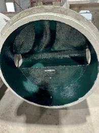
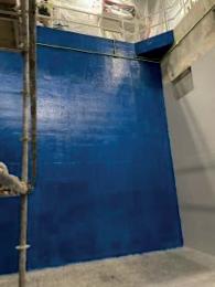
TCI ShieldStrong 955: Chemical-Resistant Protective Coating System for Concrete and Steel Infrastructure
for sewer and wastewater facilities.
TCI ShieldStrong™ 955 is a cost-effective, high-performance protective lining system designed to extend the life of concrete and steel structures in the harshest environments. It’s being used to protect new infrastructure before it goes in the ground— and to rehabilitate aging assets on some of the largest infrastructure projects across North America.


19th Annual Western No-Dig Conference and Good Practice Course
ASU | SkySong, 1301 N Scottsdale Road, Scottsdale, AZ 85257
Southeast 2025 Trenchless Conference
University of North Florida, Jacksonville, FL 32224
9th Annual South Central Trenchless Technology Conference
University of Texas at Arlington, Bluebonnet Ballroom, 300 W First Street, Arlington, TX 76019
Northeast Chapter 2025 Annual Trenchless Conference
Sheraton Nashua, 11 Tara Blvd, Nashua, NH 03062
NASTT 2025 No-Dig North & ISTT International No-Dig
Vancouver Convention Centre, 1055 Canada Place, Vancouver, BC V6C 0C3
• October 27, 2025, 8:00 am – 12:00 pm:
NASTT’s Introduction to Trenchless Technology –New Installations
• October 27, 2025, 8:00 am – 5:00 pm:
NASTT’s CIPP Good Practices Course
• October 27, 2025, 8:00 am – 5:00 pm: NASTT’s HDD Good Practices Course
• October 27, 2025, 8:00 am – 5:00 pm: NASTT’s Direct Steerable Pipe Thrusting Good Practices Course
• October 27, 2025, 1:00–5:00 pm:
NASTT’s Introduction to Trenchless Technology –Rehabilitation
6th Annual Trenchless Elevated Conference Conference Center at Miller Campus, 9750 S 300 W, Sandy, UT 84070
NASTT 2026 No-Dig Show
277 N Avenida Caballeros, Palm Springs, CA 92262
By Thomas Husch, P.Tech.(Eng), CCI Inc., Edmonton, Alberta

The collection of survey data of trenchless pipeline installation poses many challenges. These challenges range from inaccuracies in steering, changes in the shape of an HDD borehole during reaming, interference due to vibration or nearby electromagnetic fields, low data frequency, and more. Use of a Track Check gyroscopic survey tool, to complete a pipe in place survey of a pipe after it has been installed by trenchless means can add a greater degree of certainty to the quality of the trenchless installation by confirming the final location and geometry of the pipe. This paper will review some of the challenges of using typical trenchless construction asbuilt data, real-world examples comparing initial survey data from HDD pilot holes or tunneling data to secondary survey data. Noted differences in overall location pipe geometry and bending radii will be assessed for the example provided and implications in construction and potentially future designs will be reviewed.
Pipe in place surveys of trenchless installations are an additional step that should be considered during pipeline construction. While not standard across the industry, these surveys can provide a great deal of additional information that confirms the location and geometry of the as-built
pipelines. These surveys can be particularly useful on longer installations such as on installations via Horizontal Directional Drill (HDD). During HDD construction, it is typical, at a minimum, to record pilot hole data that logs the location of the steering tool sensor (typically a short distance behind the bit) at intervals equal to the length of each drill pipe segment. This location data is often used as the as-built location of the pipe for the trenchless installation. Multiple challenges can be presented that make the pilot hole data less reliable.
Construction data from HDD trenchless installations are typically recorded from one of three generalized types of steering systems; walkover, wireline, and gyroscopic. All systems can vary significantly by manufacturer. HDD steering technology continues to be developed, though key challenges will remain, some which are specific to the steering system, and others may occur irrelevant of the type of system being used.
1. Boreholes are typically drilled to a diameter that is larger than the product pipe to reduce the friction on the pipe as it is pulled into the borehole. This larger diameter lets the pipe conform to radii that may be different than those calculated by the pilot hole data. This has potential stress implications
2. During reaming, the overall position of a borehole can move, depending on ground conditions and centralization of the reaming tools. An example of this is the borehole sinking to a lower elevation due to frequent trips through a borehole in soft ground with heavy reamers. This can have implications for the geometry and overall location of the as-built pipeline.
3. Tie in information – The data from pilot hole surveys are often only provided in a local grid system. Data to reference this local system to the overall project grid is frequently either poorly documented or assumed. This can result in inaccuracies in the overall position and orientation of the as-built data.
4. Data intervals – Pilot hole data is typically provided at an interval of one coordinate per length of drill pipe. This provides a limited data sample and there is potential for the as-built pipe to confirm to radii not represented by the data due to gaps in the data.
5. Data format – Pilot hole data is often provided in a local coordinate system to facilitate steering of the drill bit. People not familiar with the data format may incorrectly interpret and transform the data, resulting in incorrect records.
6. Walkover – This system is most common for shallow installations. Key limitation is the frequent absence of left/right or
azimuth data. This can have implications for the geometry and overall location of the as-built pipeline.
7. Wireline – Another common system that utilizes magnetic signals from a surface coil to calculate the horizontal position of the steering sensor. Typical accuracy of these is 2% of the depth of the tool. Magnetic interference from any other magnetic fields near the installation can be distorted.
8. Gyroscopic – These systems can vary greatly by manufacturer. The surveys from these tools can be impacted by inadequate north-seeking or calibration.
Considering the above factors, implementing an additional survey step to confirm the position of the pipe after it has been installed in the borehole would be a prudent decision. To further illustrate this, we can review a comparison of data sets showing the differences and discrepancies that can be seen when comparing two or more data sets.
The true location of the pipe after it is installed is the key component of as-built data required for most projects. Accurate spatial data for constructed pipelines is critical in the planning of new construction and any ground disturbance activities nearby. Data that is uncertain due to potential changes in the borehole during construction, or shortcomings of the pilot hole data, can increase the risk of conflicts or in some cases, even line strikes.
DURING REAMING
Changes in the borehole position during reaming can be a result of numerous factors. In the example provided below, there was an HDD that was drilled through very soft cohesive soils. Multiple reams were also required to enlarge the borehole to the required diameter. Due to multiple reaming passes required, as well as additional trips to condition the borehole, the result was that the heavy reamers sank in the soft soil. This can be seen in the final position of the installed pipeline when compared to the initial pilot hole survey. Due to other complications during construction, subsequent steering tool runs after the final ream pass were the initial indication that the reamers had cut a hole that ended up over 5 metres lower than what was shown in the pilot hole data. The figure below shows an example of the survey profiles from the crossing. It
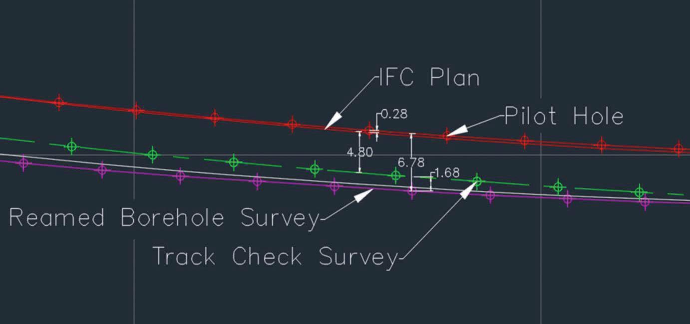
shows the pilot hole was completed along the engineered design. After reaming, a steering tool was run through the borehole and shows the bottom of the borehole at 6.78 metres below the pilot hole.
The survey (Track Check Survey) of the installed pipeline differs from both surveys.
While this is an extreme case, it illustrates that it is probable in many cases, that the pipe does not follow the profile of the pilot hole.
While spatial data is critical for records, ground disturbance, and planning adjacent construction, the geometry of the pipe has a direct impact on the operation of the pipeline. As pipe is pulled into the borehole, the pipe conforms to the overall shape of the borehole which imposes a condition of elastic bending on the pipe. For high pressure pipelines, the bending stress imposed on the pipeline is a key component to the operating (shear) stress.
Specifications and guidelines that typically govern stress on high pressure oil and gas pipelines are:
• ASME B31.8
• CSA Z662
• PRCI PR-277-144507
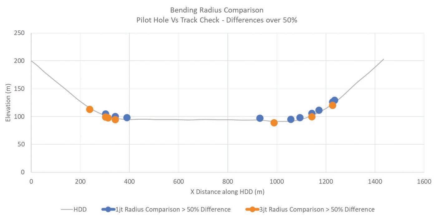
The true radius to which the pipe conforms is critical data to accurately assess the overall stress imposed on the pipe under operating conditions. In the above section, the potential for changes in borehole position has already been demonstrated. If the position of the borehole is different than the pilot hole, it is clear that there is potential for the geometry to change as well. The figure below shows a comparison of radii based on pilot hole survey data against a post installation survey (limited to the curved portions of the HDD only). This shows that there are multiple instances throughout the curved portion of the HDD where significant differences are recorded between the two surveys.
The bending radius of a pipe must be calculated over a prescribed distance. PRCI PR-277-44507-R01, section 5.3.2 recommends the formula below to calculate the approximate radius of a circular curve through which a pipe is pulled:
R = (L/A) * 688
Where:
L = length in feet
A = total angle change over L in degrees
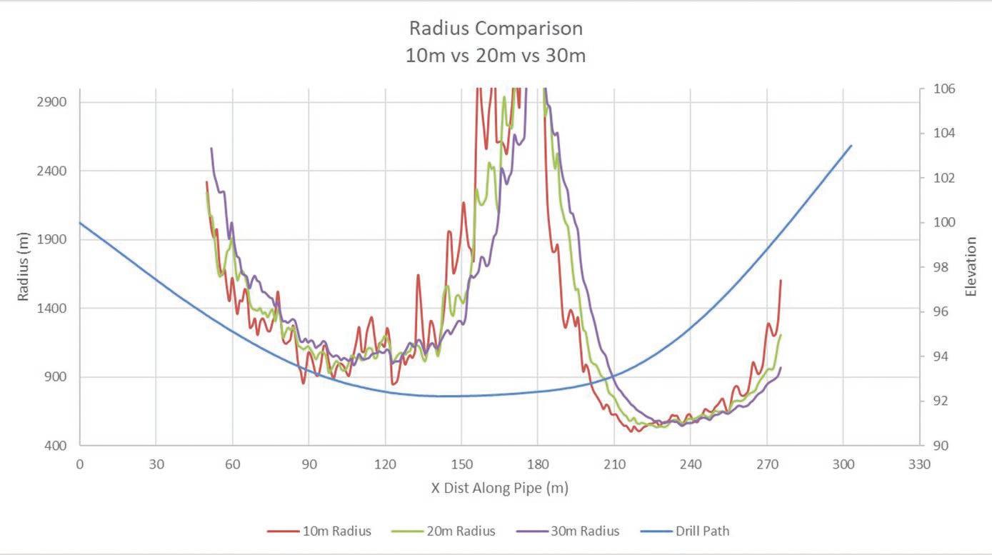
The selection of L is left up to engineering judgement. Increased use of post installation surveys of pipe can be used to further inform this engineering judgement. Much of the allowance for engineering judgement is to allow for assessments of the pipes ability to conform to radii through the oversized borehole that may be different from what is shown in the pilot hole data. Post-installation surveys of the pipe will show if the pipe is conforming to radii over shorter or longer lengths. These surveys remove the challenges of assessing how the pipe will conform to a borehole that is oversized. The below figure shows and example of a pipe that shows clear instances of a pipe conforming to radii over 10 metre distances that are smaller than the radii calculated over 30 metre distances. The fact that the minimum 10 metres radius is lower than the 20 metres or 30 metres radius shows that the pipe is conforming to the radius over the shorter distance and should be considered in the stress calculations.
There are several tools and methods available to measure pipelines after they have been installed in an HDD. There is considerable
benefit to scheduling the survey to be completed as soon as possible after the HDD is installed. Tethered gyroscopic tools, such as the Track Check survey tool, are capable of accurately surveying an HDD installation before it is tied into the remainder of the pipeline.
These surveys provide the advantages discussed above including:
• True location of the pipe is surveyed.
• Data resolution allows for survey coordinates at 1m intervals, or less (compared to 1coordinate per joint of drill pipe).
• Data can be provided in project grid coordinates.
These surveys can be completed very quickly on site. Each crossing can often be completed in half a day or less. Surveys are completed by pulling the tool one way through the pipe for the initial survey,
then pulling the tool back to the starting side to have a second data set. Once the two data sets are compared to confirm accuracy and repeatability of the survey, the data can be made available for further engineering analysis.
Implementation of a post installation survey of pipelines installed by HDD’s adds a considerable level of confidence to the spatial data records, as well as allowing for reduced assumptions in the stress analysis of the pipeline.
PR-277-144507-R01, Installation of Pipelines by Horizontal Directional Drilling, an Engineering Design Guide, Pipeline Research Council International, Inc. (PRCI).
Today’s forest industry is working hard to become one of the greenest industries on earth.
Paper is an essential part of human civilization. While we all use and depend upon electronic communications, it is easy to ignore that it comes at an environmental cost. Worldwide spam email traffic creates greenhouse gases equivalent to burning two billion gallons of gasoline yearly, with numbers rising. More than $55 billion in toxic e-waste material is thrown away every year in the US alone, with a recycling rate of only 20% compared to 64.7% for paper.
No industry is perfect. But the paper industry has made, and continues to make, huge investments in environmental responsibility. Specifying and buying paper from certified sources ensures the continuation and growth of carbon absorbing forests. Using paper with appropriate amounts of recycled fibre helps preserve forests, conserve energy, and maximize fibre usage through paper lifecycles.

The NW Trenchless Journal is made possible by the companies below who convey their important messages on our pages. We thank them for their support of NASTT-NW and its publication and encourage you to contact them when making your purchasing decisions. To make it easier to contact these companies, we have included the page number of their advertisement, their phone number, and, where applicable, their website.
Instead of digging up the entire sewer line our non-destructive No Dig sewer line point repairs are done by accessing the damaged pipe through manhole locations. Our repair sleeve is inserted into the pipe directly from the manhole and delivered to the damaged section of pipe. The sleeve is then expanded by our inflatable packer and compressed against the inner pipe wall where it is permanently locked into position.
We utilize the QuickLock point repair system which can be used on pipe diameters of 6” to 30” and repair the following defects:
• Infiltrations
• O ffset joints
• Abandoned laterals
• Root intrusions
• Holes
• Longitudinal & circumferential cracks
• Restore structural integrity of pipe
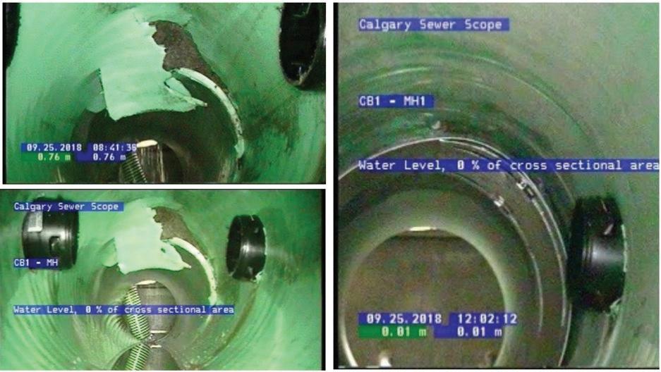

403-536-1415 | calgarysewerscope.ca info@calgarysewerscope.ca

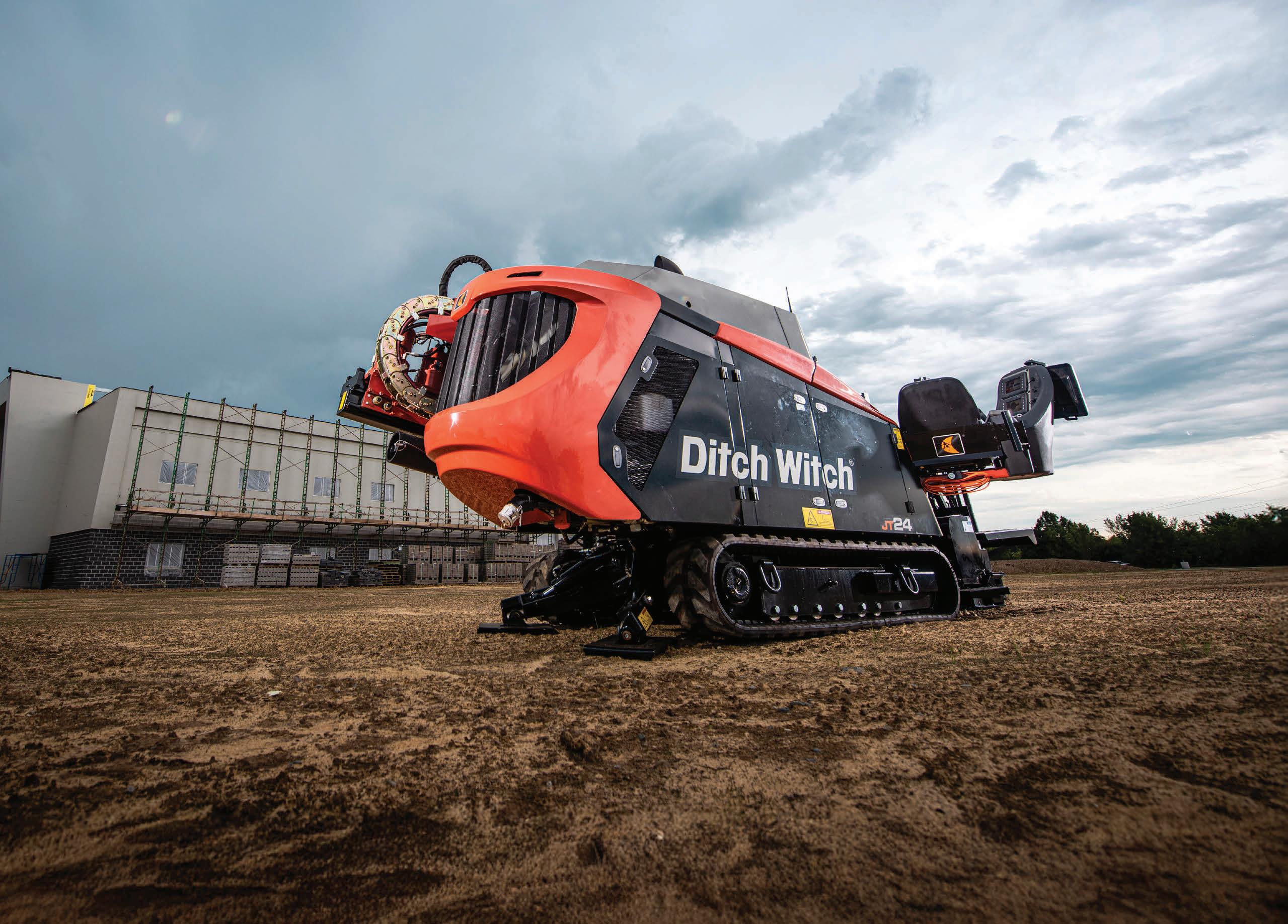

Tackle tight jobsites and tough ground with drills that don’t hold back. The Ditch Witch® JT24 delivers the torque you need and the reliability you count on—so you can stay productive, stay efficient, and stay ahead.
Drill through tough jobs faster with 28,000 lbs of thrust in a tight, nimble frame.
Bore clean and accurate with less surface repair and fewer delays.
Keep drilling with 100+ Brandt service points and rapid parts delivery, nationwide.


•
•
•
•
•