
Shutdown SIS
Previous Screen
Product: EXCAVATOR
Model: 320D2 EXCAVATOR YBK
Configuration: 320D2 & 320D2 L Excavators YBK00001-UP (MACHINE) POWERED BY C7.1 Engine
Disassembly and Assembly
C7.1 (Mech) Engines for Caterpillar Built Machines
Flywheel - Remove
SMCS - 1156-011
Removal Procedure
Table 1
Required Tools
Start By:
a. Remove the electric starting motor. Refer to Disassembly and Assembly, "Electric Starting Motor - Remove and Install" for the correct procedure.
NOTICE
Keep all parts clean from contaminants.
Contaminants may cause rapid wear and shortened component life.
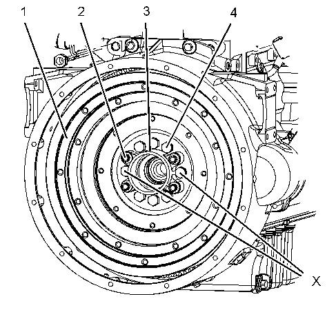
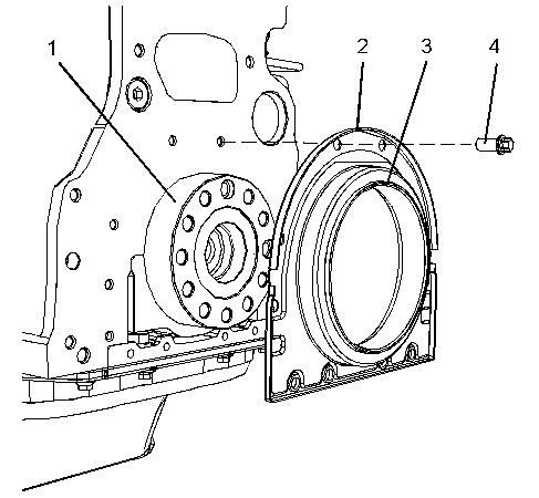
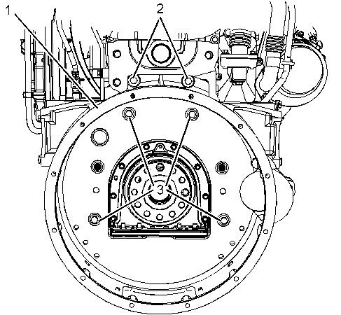
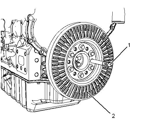
Illustration 1
Typical example
1. Remove bolts from Position (X) from flywheel (1).
2. Install Tooling (A) in Position (X) to flywheel (1).
g01336668
3. Install a suitable lifting device onto flywheel (1). Support the weight of the flywheel. The flywheel can weigh 71 kg (156 lb).
4. If necessary, remove bolts (2) that secure the housing for pilot bearing (3) to flywheel (1). Remove the housing for pilot bearing (3).
5. Remove remaining bolts (4).
6. Use the lifting device to remove the flywheel from the engine.
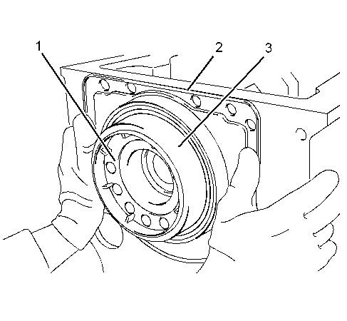
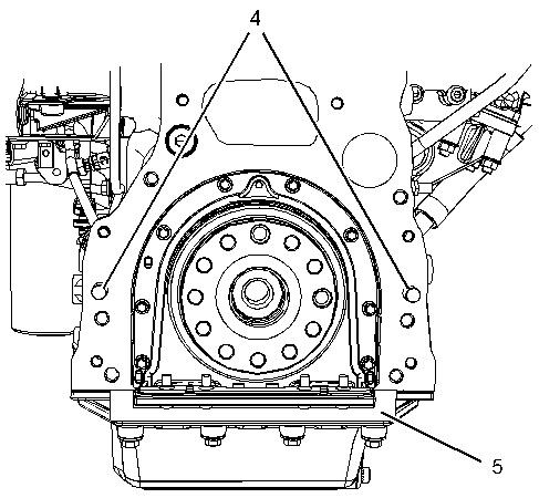
Illustration 2
Typical example
g01336669
7. Inspect flywheel (1) and ring gear (5) for wear and damage. Replace any worn components or damaged components.
8. To remove flywheel ring gear (5), follow Step 8.a through Step 8.b.
a. Place the flywheel assembly on a suitable support.
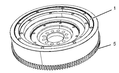
b. Use a hammer and a punch in order to remove ring gear (5) from flywheel (1).
Note: Identify the orientation of the teeth on the flywheel ring gear.
Previous Screen
Product: EXCAVATOR
Model: 320D2 EXCAVATOR YBK
Configuration: 320D2 & 320D2 L Excavators YBK00001-UP (MACHINE) POWERED BY C7.1 Engine
Disassembly and Assembly
C7.1 (Mech) Engines for Caterpillar Built Machines
Flywheel - Install
SMCS - 1156-012
Installation Procedure Table 1
Required Tools
NOTICE
Keep all parts clean from contaminants.
Contaminants may cause rapid wear and shortened component life.
Shutdown SIS
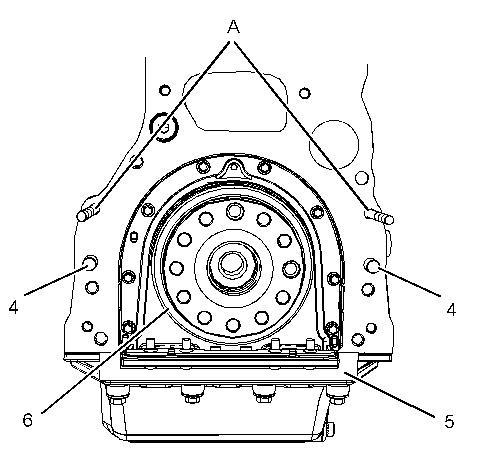
Illustration 1
Typical example
g01336671
Always wear protective gloves when handling parts that have been heated.
1. If the flywheel ring gear was removed, follow Step 1.a through Step 1.c in order to install ring gear (5) to flywheel (1).
a. Identify the orientation of teeth (6) on new ring gear (5).
Note: The chamfered side of ring gear teeth (6) must face toward the starting motor when the flywheel is installed. The chamfered side of ring gear teeth ensures the correct engagement of the starting motor.
b. Heat flywheel ring gear (5) in an oven to a maximum temperature of 250 °C (482 °F) prior to installation.
Note: Do not use a torch to heat the ring gear.
c. Ensure that the orientation of ring gear (5) is correct and quickly install the ring gear onto flywheel (1).
2. Inspect the crankshaft rear seal for leaks. If there are any oil leaks, replace the crankshaft rear seal. Refer to Disassembly and Assembly, "Crankshaft Rear Seal - Install" for the correct procedure.
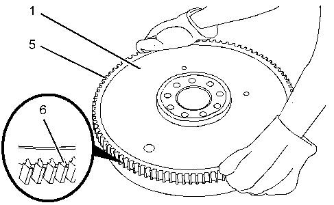
Illustration 2
Typical example
g01336668
3. Install a suitable lifting device onto flywheel (1). The flywheel can weigh 71 kg (156 lb).
4. Install Tooling (A) in Position (X) on the crankshaft.
5. Use the lifting device to position flywheel (1) onto Tooling (A).
6. If necessary, install pilot bearing (3) and bolts (2) to flywheel (1).
7. Install bolts (4) to flywheel (1).
8. Remove Tooling (A) and install remaining bolts (4) to flywheel (1).
9. Use a suitable tool to prevent the flywheel from rotating. Tighten bolts (2) and (4) to a torque of 140 N·m (103 lb ft).
10. Remove the lifting device from flywheel (1).
11. Check the run out of the flywheel. Refer to Specifications, "Flywheel" for further information.
End By:
a. Install the electric starting motor. Refer to Disassembly and Assembly, "Electric Starting Motor - Remove and Install" for the correct procedure.
Shutdown SIS
Previous Screen
Product: EXCAVATOR
Model: 320D2 EXCAVATOR YBK
Configuration: 320D2 & 320D2 L Excavators YBK00001-UP (MACHINE) POWERED BY C7.1 Engine
Disassembly and Assembly
C7.1 (Mech) Engines for Caterpillar Built Machines
Crankshaft Rear Seal - Remove
SMCS - 1161-011
Removal Procedure Table 1
Required Tools
Tool Part Number Part Description Qty
A 227-4389 E10 Torx Socket 1
Start By:
a. Remove the flywheel. Refer to Disassembly and Assembly, "Flywheel - Remove".
NOTICE
Keep all parts clean from contaminants.
Contaminants may cause rapid wear and shortened component life.
NOTICE
Care must be taken to ensure that fluids are contained during performance of inspection, maintenance, testing, adjusting and repair of the product. Be prepared to collect the fluid with suitable containers before opening any compartment or disassembling any component containing fluids.
Dispose of all fluids according to local regulations and mandates.
Note: The crankshaft rear seal and the housing are manufactured as a one-piece assembly. The assembly is not serviceable. If the crankshaft rear seal is removed, the assembly must be replaced.
1. Use Tooling (A) in order to remove torx screws (1) from crankshaft rear seal (2).
2. Remove crankshaft rear seal (2) from the cylinder block. Discard the crankshaft rear seal. Copyright 1993 - 2020 Caterpillar Inc. All Rights Reserved.
Illustration 1 g02711971Shutdown SIS
Previous Screen
Product: EXCAVATOR
Model: 320D2 EXCAVATOR YBK
Configuration: 320D2 & 320D2 L Excavators YBK00001-UP (MACHINE) POWERED BY C7.1 Engine
Disassembly and Assembly
C7.1 (Mech) Engines for Caterpillar Built Machines
Crankshaft Rear Seal - Install
SMCS - 1161-012
Installation Procedure Table 1
Required Tools
Tool Part Number Part Description Qty
A 227-4389 E10 Torx Socket 1
B FT-2806 Alignment Tool 1
Note: The crankshaft rear seal and the housing are manufactured as a one-piece assembly.
NOTICE
Keep all parts clean from contaminants.
Contaminants may cause rapid wear and shortened component life.
g02717045
1. Ensure that crankshaft flange (1) is clean, dry, and free from damage.
2. Ensure that the face of the cylinder block and the bridge piece are clean and dry.
3. A new crankshaft rear seal is supplied with a plastic sleeve (3). Ensure that the plastic sleeve is squarely installed within crankshaft rear seal (2).
Note: The plastic sleeve is included in order to protect the lip of the seal as the seal is pushed over the crankshaft flange.
Note: Do not lubricate the crankshaft rear seal or the crankshaft flange. The crankshaft rear seal must be installed dry.
4. Align plastic sleeve (3) with crankshaft flange (1). Ensure that the plastic sleeve is engaged onto the crankshaft flange. Push new crankshaft rear seal (2) squarely onto the crankshaft flange.
During this process, the plastic sleeve will be forced out of the crankshaft rear seal. Discard the plastic sleeve.
5. Ensure that crankshaft rear seal (2) is seated against the cylinder block.
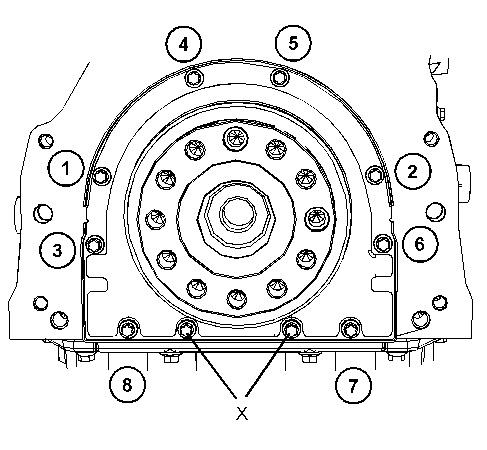
g02717046
6. Install torx screws (4) finger tight.
Note: Do not install torx screws to Positions (X) at this stage.
7. Install Tooling (B) to crankshaft rear seal (2) and to crankshaft flange (1). Use Tooling (B) to align crankshaft rear seal (2) with crankshaft flange (1).
8. Use Tooling (A) in order to tighten torx screws (4) to a torque of 22 N·m (195 lb in). Tighten torx screws (4) in the sequence that is shown in Illustration 3.
9. Remove Tooling (B).
10. Install remaining torx screws (4) to Positions (X). Use Tooling (A) in order to tighten the torx screws to a torque of 22 N·m (195 lb in). Refer to Illustration 3.
End By:
a. Install the flywheel. Refer to Disassembly and Assembly, "Flywheel - Install".
Previous Screen
Product: EXCAVATOR
Model: 320D2 EXCAVATOR YBK
Configuration: 320D2 & 320D2 L Excavators YBK00001-UP (MACHINE) POWERED BY C7.1 Engine
Disassembly and Assembly
C7.1 (Mech) Engines for Caterpillar Built Machines
Shutdown SIS
Flywheel Housing - Remove and Install - Standard Housing
SMCS - 1157-010
Removal Procedure
Table 1
Required Tools
Start By:
a. Remove the flywheel. Refer to Disassembly and Assembly, "Flywheel - Remove" for the correct procedure.
NOTICE
Keep all parts clean from contaminants.
Contaminants may cause rapid wear and shortened component life.
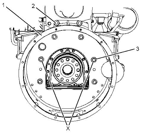
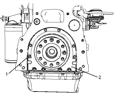
Illustration 2
Typical example
1. Remove bolts (3) from Position (X) from flywheel housing (1).
2. Install Tooling (A) into Position (X) on flywheel housing (1).
g02227474
3. Install a suitable lifting device onto the flywheel housing in order to support the flywheel housing. The weight of the flywheel housing is approximately 40 kg (88 lb).
4. Remove bolts (2) and remaining bolts (3) from flywheel housing (1).
5. Use a suitable lifting device in order to remove flywheel housing (1) from the cylinder block.
6. Remove dust seal (5).
7. If necessary, remove dowels (4) from the cylinder block.
Keep all parts clean from contaminants.
Contaminants may cause rapid wear and shortened component life.
1. Ensure that the flywheel housing is clean and free from damage. If necessary, replace the flywheel housing.
g01983535
Typical example
2. Inspect crankshaft rear seal (6) for leaks. If there are any oil leaks, replace the crankshaft rear seal. Refer to Disassembly and Assembly, "Crankshaft Rear Seal - Remove" and refer to Disassembly and Assembly, "Crankshaft Rear Seal - Install" for the correct procedure.
3. Clean the rear face of the cylinder block. If necessary, install dowels (4) to the cylinder block.
4. Install Tooling (A) to the cylinder block.
5. Install dust seal (5).
Illustration 4Illustration 5
Typical example
g02227475
6. Install a suitable lifting device onto the flywheel housing. The weight of the flywheel housing is approximately 40 kg (88 lb).

7. Use the lifting device to align flywheel housing (1) with Tooling (A). Install the flywheel housing to the cylinder block.
8. Install bolts (2) and bolts (3).
9. Remove Tooling (A). Install remaining bolts (3).
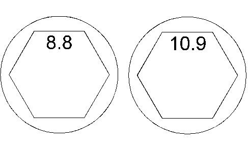
Illustration 6
Identification of the bolt Grade.
g01984554
10. When 8.8 Graded bolts are installed, follow Step 10.a through Step 10.b.
a. Tighten bolts (3) to a torque of 63 N·m (46 lb ft).
b. Tighten bolts (2) to a torque of 78 N·m (58 lb ft).
11. When 10.9 Graded bolts are installed follow Step 11.a through Step 11.b.
a. Tighten bolts (3) to a torque of 115 N·m (85 lb ft).
b. Tighten bolts (2) to a torque of 190 N·m (140 lb ft).
12. Check the alignment of flywheel housing (1) with the crankshaft. Refer to System Operation, Testing and Adjusting, "Flywheel Housing - Inspect" for more information.
End By:
a. Install the flywheel. Refer to Disassembly and Assembly, "Flywheel - Install" for the correct procedure.
Shutdown SIS
Previous Screen
Product: EXCAVATOR
Model: 320D2 EXCAVATOR YBK
Configuration: 320D2 & 320D2 L Excavators YBK00001-UP (MACHINE) POWERED BY C7.1 Engine
Disassembly and Assembly
C7.1 (Mech) Engines for Caterpillar Built Machines Media
Vibration Damper and Pulley - Remove
SMCS - 1205-011
Removal Procedure
Table 1
Required Tools
Start By:
A. Remove the alternator belt. Refer to Disassembly and Assembly, "V- Belts - Remove and Install" for the correct procedure.
Note: The weight of the assembly of the crankshaft pulley, the vibration damper, and the crankshaft adapter is approximately 22 kg (48 lb).
Suggest:
If the above button click is invalid.
Please download this document first, and then click the above link to download the complete manual.
Thank you so much for reading

Illustration 1
g02717789
1. Use a suitable tool in order to prevent the crankshaft from rotating. Use Tooling (B) to remove one Torx screws (1) from crankshaft pulley assembly (2) .
2. Install Tooling (A) into crankshaft pulley assembly (2) .
3. Remove remaining Torx screws (1) from crankshaft pulley assembly (2) .
4. Remove crankshaft pulley assembly (2) .
5. Tooling (A) .