
Shutdown SIS
Previous Screen
Product: EXCAVATOR
Model: 320D2 EXCAVATOR ZBM
Configuration: 320D2 & 320D2 L Excavators ZBM00001-UP (MACHINE) POWERED BY C7.1 Engine
Disassembly and Assembly
C7.1 (Mech) Engines for Caterpillar Built Machines
Fuel Injection Pump - Remove - With Boost Control
SMCS - 1251-011
Removal Procedure
Table 1
Required Tools
( 1 ) The Crankshaft Turning Tool is used on the front pulley.
( 2 ) This Tool is used in the aperture for the electric starting motor.
Start By:
A. Remove the front cover. Refer to Disassembly and Assembly, "Front Cover - Remove and Install" for the correct procedure .
B. Remove the fuel injection lines. Refer to Disassembly and Assembly, "Fuel Injection Lines - Remove" for the correct procedure.
Note: Either Tooling (A) can be used. Use the Tooling that is most suitable.
Contact with high pressure fuel may cause fluid penetration and burn hazards. High pressure fuel spray may cause a fire hazard. Failure to follow these inspection, maintenance and service instructions may cause personal injury or death.
NOTICE
Ensure that all adjustments and repairs that are carried out to the fuel system are performed by authorized personnel that have the correct training.
Before beginning ANY work on the fuel system, refer to Operation and Maintenance Manual, "General Hazard Information and High Pressure Fuel Lines" for safety information.
Refer to System Operation, Testing and Adjusting, "Cleanliness of Fuel System Components" for detailed information on the standards of cleanliness that must be observed during ALL work on the fuel system.
1. Turn the fuel supply to the OFF position.
2. Turn the battery disconnect switch to the OFF position.
g02791601
3. Use Tooling (A) in order to rotate the crankshaft so that number one piston is at top dead center position . Refer to System Operation, Testing and Adjusting, "Finding Top Center Position for No.1 Piston" for the correct procedure.
4. Use Tooling (B) in order to lock the crankshaft so that number one piston is at top dead center position.
5. Use Tooling (C) in order to lock the camshaft.
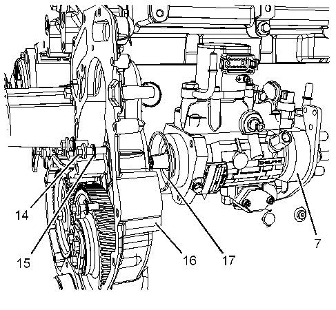
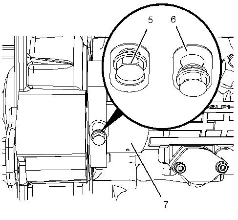
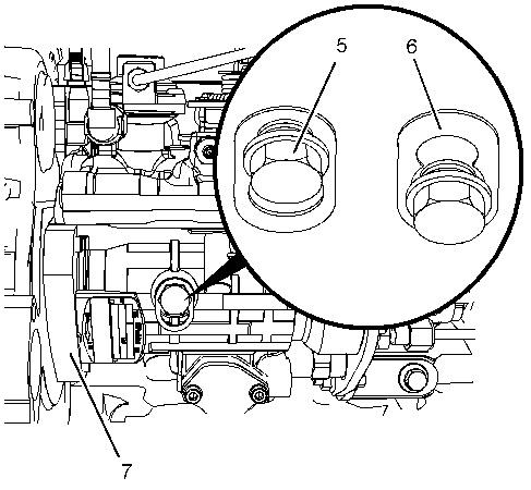
6. Loosen locking screw (1) . Rotate spacer (2) in order to allow locking screw (1) to tighten against the shaft of the fuel injection pump. Rotate the fuel injection pump gear in a counterclockwise direction in order to remove the backlash. Tighten locking screw (1) to a torque of 15 N·m (133 lb in).
Note: Locking the screw must be tightened in order to prevent the shaft of the fuel injection pump from rotating. The shaft of the fuel injection pump must not be rotated after the fuel injection pump has been removed from the engine.
7. Remove the backlash from the fuel pump gear. Lock the fuel injection pump in the correct position and remove the fuel pump gear. Refer to Disassembly and Assembly, "Fuel Pump Gear - Remove and Install" for the correct procedure.
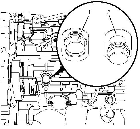
Illustration 2
g02791603
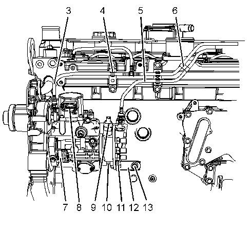
8. Clean fuel injection pump (8) and the area around the fuel injection pump. Ensure that the area is free from contamination before beginning disassembly.
9. Place a suitable container below fuel injection pump (8) in order to catch any fuel that might be spilled.
10. Disconnect plastic tube assembly (3) , plastic tube assembly (4) , and plastic tube assembly (6) from fuel injection pump (8) .
11. Remove plastic tube assembly (3) , plastic tube assembly (4) , and plastic tube assembly (6) from clips (5) and clip (7) . Position the plastic tube assemblies away from the fuel injection pump.
12. Use Tooling (D) in order to plug plastic tube assembly (3) , plastic tube assembly (4) , and plastic tube assembly (6) .
13. Use Tooling (D) in order to cap connections for the plastic tube assemblies on fuel injection pump (8) .
14. Remove tube assembly (9) from fuel injection pump (8) and the cylinder head.
15. Remove seal (10) (not shown).
16. Disconnect the OEM harness assemblies from solenoid (11) and solenoid (12) .
17. Remove the nut and bolt (13) from fuel injection pump (8) .
18. Remove bolt (15) and remove bracket (14) from the cylinder block and the fuel injection pump.
Illustration 3 g02791604
19. Remove bolts (17) and sealing washers (16) from fuel injection pump (8) .
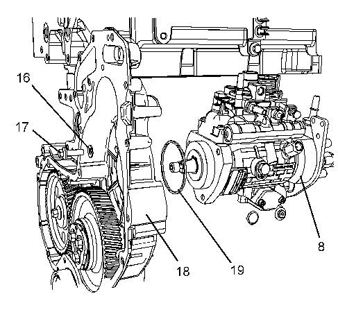
Note: The fuel injection pump should be supported by hand as the bolts are removed.
20. Carefully remove fuel injection pump (8) from front housing (18) .
21. Remove O-ring seal (19) from fuel injection pump (8) .
Copyright 1993 - 2020 Caterpillar Inc.
All Rights Reserved.
Private Network For SIS Licensees.
Shutdown SIS
Previous Screen
Product: EXCAVATOR
Model: 320D2 EXCAVATOR ZBM
Configuration: 320D2 & 320D2 L Excavators ZBM00001-UP (MACHINE) POWERED BY C7.1 Engine
Disassembly and Assembly
C7.1 (Mech) Engines for Caterpillar Built Machines
Fuel Injection Pump - Install - With Boost Control
SMCS - 1251-012
Installation Procedure Table 1
Required Tools
1
(1) The Crankshaft Turning Tool is used on the front pulley.
(2) This Tool is used in the aperture for the electric starting motor.
Note: Either Tooling (A) can be used. Use the Tooling that is most suitable.
NOTICE
Ensure that all adjustments and repairs that are carried out to the fuel system are performed by authorized personnel that have the correct training.
Before beginning ANY work on the fuel system, refer to Operation and Maintenance Manual, "General Hazard Information and High Pressure Fuel Lines" for safety information.
Refer to System Operation, Testing and Adjusting, "Cleanliness of Fuel System Components" for detailed information on the standards of cleanliness that must be observed during ALL work on the fuel system.
1. Inspect the bore in the front housing for damage. If the bore is damaged, replace the front housing. Refer to Disassembly and Assembly, "Housing (Front) - Remove" for the correct procedure.
2. Install a new O-ring seal (19) to fuel injection pump (8).
3. Install new sealing washers (16) to bolts (17).
4. Carefully install fuel injection pump (8) to front housing (18).
Note: The fuel injection pump should be supported by hand as the bolts are installed.
5. Install bolts (17) to fuel injection pump (8) hand tight.
6. Tighten bolts (17) to a torque of 22 N·m (195 lb in).
Illustration 1 g02791604
Illustration 2
g02791603
Illustration 3
g02792516
7. Position bracket (14) onto the cylinder block and the fuel injection pump. Install bolt (15) to the cylinder block finger tight.
8. Install the nut and bolt (13) to fuel injection pump (8) finger tight.
9. Tighten bolts (15) to a torque of 44 N·m (32 lb ft). Tighten the nut and bolt (13) to a torque of 22 N·m (195 lb in).
Note: Ensure that the fuel injection pump is not stressed as the bolts for the bracket are tightened.
10. Ensure that the No. 1 cylinder is at top dead center on the compression stroke. Refer to Systems Operation, Testing and Adjusting, "Fuel Injection Timing - Check". If necessary, use Tooling (A) in order to rotate the crankshaft so that number one piston is at the top center position on the compression stroke. Refer to Systems Operation, Testing and Adjusting, "Finding Top Center Position for No.1 Piston" for the correct procedure.
11. Use Tooling (C) in order to lock the camshaft in the correct position. Use Tooling (B) in order to lock the crankshaft in the correct position.
12. Install the fuel injection pump gear to fuel injection pump (8). Refer to Disassembly and Assembly, "Fuel Injection Pump Gear - Install".
13. Remove Tooling (C) and Tooling (B).
14. Install the fuel injection lines. Refer to Disassembly and Assembly, "Fuel Injection LinesInstall" for the correct procedure.
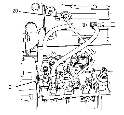
15. Install a new seal (10) (not shown) to tube assembly (9).
16. Connect tube assembly (9) to fuel injection pump (8) and the cylinder head.
17. Tighten tube nut (20) to a torque of 8 N·m (71 lb in).
18. Tighten tube nut (21) to a torque of 6 N·m (53 lb in).
19. Remove the plugs from fuel injection pump (8).
20. Remove the caps from plastic tube assembly (3), plastic tube assembly (4), and plastic tube assembly (6).
21. Connect plastic tube assembly (3), plastic tube assembly (4), and plastic tube assembly (4) to fuel injection pump (8).
22. Install plastic tube assembly (3), plastic tube assembly (5), and plastic tube assembly (6) to clips (5) and clip (7).
23. Connect the OEM harness assemblies to solenoid (11) and solenoid (12).
24. Loosen locking screw (1). Rotate spacer (2) in order to allow locking screw (1) to tighten against spacer (2). Tighten locking screw (1) to a torque of 12 N·m (106 lb in).
Note: Ensure that the fuel injection pump is in the unlocked position.
25. Turn the fuel supply to the OFF position.
26. Turn the battery disconnect switch to the ON position.
27. Remove the air from the fuel system. Refer to Operation and Maintenance Manual, "Fuel System - Prime" for the correct procedure.
End By:
a. Install the front cover. Refer to Disassembly and Assembly, "Front Cover - Remove and Install" for the correct procedure .
Copyright 1993 - 2020 Caterpillar Inc.
All Rights Reserved.
Private Network For SIS Licensees.
Sat Jan 18 00:10:09 UTC+0800 2020
Previous Screen
Product: EXCAVATOR
Model: 320D2 EXCAVATOR ZBM
Configuration: 320D2 & 320D2 L Excavators ZBM00001-UP (MACHINE) POWERED BY C7.1 Engine
Disassembly and Assembly
C7.1 (Mech) Engines for Caterpillar Built Machines
Shutdown SIS
Fuel Injection Pump - Install - With Electronic Governor
SMCS - 1251-012
Installation Procedure Table 1
Required Tools
1
(1) The Crankshaft Turning Tool is used on the front pulley.
(2) This Tool is used in the aperture for the electric starting motor.
Note: Either Tooling (A) can be used. Use the Tooling that is most suitable.
NOTICE
Ensure that all adjustments and repairs that are carried out to the fuel system are performed by authorized personnel that have the correct training.
Before beginning ANY work on the fuel system, refer to Operation and Maintenance Manual, "General Hazard Information and High Pressure Fuel Lines" for safety information.
Refer to System Operation, Testing and Adjusting, "Cleanliness of Fuel System Components" for detailed information on the standards of cleanliness that must be observed during ALL work on the fuel system.
1. Inspect the bore in the front housing for damage. If the bore is damaged, replace the front housing. Refer to Disassembly and Assembly, "Housing (Front) - Remove" for the correct procedure.
2. Install a new O-ring seal (17) to fuel injection pump (7).
3. Install new sealing washers (15) to bolts (14).
4. Carefully install fuel injection pump (7) to front housing (16).
Note: The fuel injection pump should be supported by hand as the bolts are installed.
5. Install bolts (14) to fuel injection pump (7) hand tight.
6. Tighten bolts (14) to a torque of 22 N·m (195 lb in).
Illustration 1 g02695516Illustration 2
g02695396
7. Position bracket (12) onto the cylinder block and the fuel injection pump. Install bolt (13) to the cylinder block finger tight.
8. Install the nut and bolt (11) to fuel injection pump (7) finger tight.
9. Tighten bolts (13) to a torque of 44 N·m (32 lb ft). Tighten the nut and bolt (11) to a torque of 22 N·m (195 lb in).
Note: Ensure that the fuel injection pump is not stressed as the bolts for the bracket are tightened.
10. Ensure that the No. 1 cylinder is at top dead center on the compression stroke. Refer to Systems Operation, Testing and Adjusting, "Fuel Injection Timing - Check". If necessary, use Tooling (A) in order to rotate the crankshaft so that number one piston is at the top center position on the compression stroke. Refer to Systems Operation, Testing and Adjusting, "Finding Top Center Position for No.1 Piston" for the correct procedure.
11. Use Tooling (C) in order to lock the camshaft in the correct position. Use Tooling (B) in order to lock the crankshaft in the correct position.
12. Install the fuel injection pump gear to fuel injection pump (7). Refer to Disassembly and Assembly, "Fuel Injection Pump Gear - Install".
13. Remove Tooling (C) and Tooling (B).
14. Install the fuel injection lines. Refer to Disassembly and Assembly, "Fuel Injection LinesInstall" for the correct procedure.
15. Remove the plugs from fuel injection pump (7).
16. Remove the caps from plastic tube assembly (3), and plastic tube assembly (5).
17. Connect plastic tube assembly (3), and plastic tube assembly (5) to fuel injection pump (7).
18. Install plastic tube assembly (3), and plastic tube assembly (5) to clips (4) and clip (6).
19. Connect the OEM harness assembly to governor (8).
20. Connect the OEM harness assemblies to solenoid (9) and solenoid (10).
21. If necessary, connect the OEM harness assemblies to solenoid (10).
Illustration 3
g02695477
22. Loosen locking screw (1). Rotate spacer (2) in order to allow locking screw (1) to tighten against spacer (2). Tighten locking screw (1) to a torque of 12 N·m (106 lb in).
Note: Ensure that the fuel injection pump is in the unlocked position.
23. Turn the fuel supply to the OFF position.
24. Turn the battery disconnect switch to the ON position.
25. Remove the air from the fuel system. Refer to Operation and Maintenance Manual, "Fuel System - Prime" for the correct procedure.
End By:
a. Install the front cover. Refer to Disassembly and Assembly, "Front Cover - Remove and Install" for the correct procedure .
Shutdown SIS
Previous Screen
Product: EXCAVATOR
Model: 320D2 EXCAVATOR ZBM
Configuration: 320D2 & 320D2 L Excavators ZBM00001-UP (MACHINE) POWERED BY C7.1 Engine
Disassembly and Assembly
C7.1 (Mech) Engines for Caterpillar Built Machines
Fuel Injection Pump Gear - Remove
SMCS - 1251-011
Removal Procedure Table 1
Required Tools
(1) The Crankshaft Turning Tool is used on the front pulley.
(2) This Tool is used in the aperture for the electric starting motor.
Start By:
a. Remove the front cover. Refer to Disassembly and Assembly, "Front Cover - Remove and Install".
Note: Either Tooling (A) can be used. Use the Tooling that is most suitable.
Keep all parts clean from contaminants.
Contaminants may cause rapid wear and shortened component life.
NOTICE
Care must be taken to ensure that fluids are contained during performance of inspection, maintenance, testing, adjusting and repair of the product. Be prepared to collect the fluid with suitable containers before opening any compartment or disassembling any component containing fluids.
Dispose of all fluids according to local regulations and mandates.
Note: Care must be taken in order to ensure that the fuel injection pump timing is not lost during the removal of the fuel pump gear. Carefully follow the procedure in order to remove the fuel pump gear.
Suggest:
If the above button click is invalid.
Please download this document first, and then click the above link to download the complete manual.
Thank you so much for reading

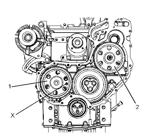
Illustration 4
With Boost Control
g02792627
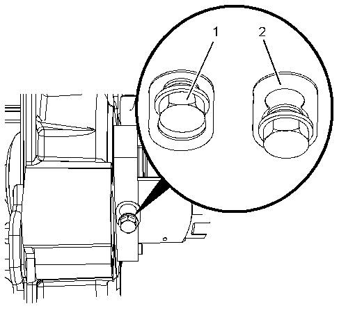
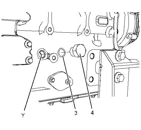
1. Remove plug (4) from the cylinder block. Remove O-ring seal (3) from plug (4).
2. Use Tooling (A) in order to rotate the crankshaft so that number one piston is at top dead center on the compression stroke. Refer to System Operation, Testing and Adjusting, "Finding Top Center Position for No.1 Piston".
3. Install Tooling (B) through Hole (X) in camshaft gear (1) into the front housing. Use Tooling (B) in order to lock the camshaft in the correct position.
4. Install Tooling (C) into Hole (Y) in the cylinder block. Use Tooling (C) in order to lock the crankshaft in the correct position.
Note: Do not use excessive force to install Tooling (C). Do not use Tooling (C) to hold the crankshaft during repairs.
5. Apply sufficient pressure to fuel injection pump gear (2) in a counterclockwise direction in order to remove the backlash. Lock fuel injection pump (2) in this position.
In order to lock fuel injection pump (7), loosen locking screw (5) in the fuel injection pump. Slide spacer (6) into the locked position. Tighten locking screw (5) against the shaft of the fuel injection pump to a torque of 15 N·m (133 lb in).