S/N - TMF1-UP
S/N - WDJ1-UP
S/N - XAN1-UP
S/N - XBB1-UP
S/N - XCC1-UP
S/N - YEA1-UP
S/N - ZBD1-UP
S/N - ZCS1-UP
Assembly Procedure
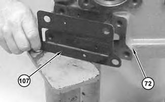
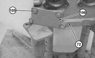
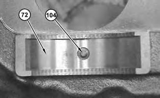
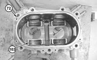 Illustration 2
g01200514
2. Install cover (106) and bolts (105) onto pump housing (72) .
Illustration 3
g01200512
Illustration 2
g01200514
2. Install cover (106) and bolts (105) onto pump housing (72) .
Illustration 3
g01200512
Illustration 4
4. Install bearings (103) onto pump housing (72) .
Illustration 5
5. Install bearing (102) into swashplate (97) .
Illustration 6
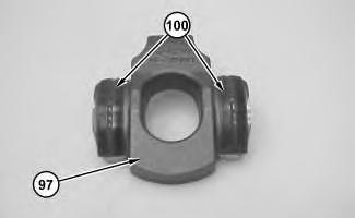
6. Install dowel pins (101) into swashplate (97) .
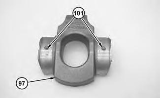
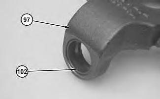
Illustration 7
7. Install bearings (100) onto swashplate assembly (97) .
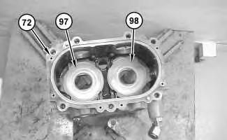
Illustration 8
8. Install plate (99) onto swashplate assembly (97) .
9. Repeat Step 5 through Step 8 for swashplate assembly (98) .
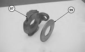
Illustration 9
10. Install swashplate assemblies (97) and (98) into pump housing (72) .
Note: The swashplate assemblies must be installed in the original position during assembly.
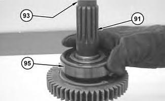
Illustration 10
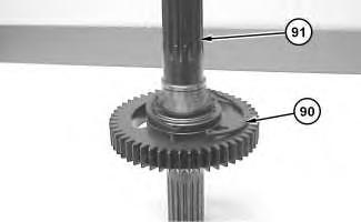
11. Install retaining ring (90) onto shaft assembly (91) .
Illustration 11
12. Raise the temperature of bearing (95) and bearing (93) . Install bearing (95) and bearing (93) onto shaft assembly (91) .
https://127.0.0.1/sisweb/sisweb/techdoc/techdoc_print_page.jsp?returnurl=/sisweb/sisw...
 g03723301
g01201656
g03723301
g01201656
Illustration 12 g01200498
13. Install ring (94) onto shaft assembly (91) .
14. Repeat Step 11 through Step 13 for shaft assembly (92) .
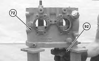
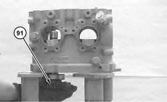
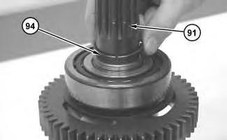
Illustration 13 g01201657
Illustration 14 g01201658
15. Lower the temperature of the shaft assemblies. Install shaft assemblies (91) and (92) into pump housing (72) .
Illustration 15
g01200492
Note: The pump has been removed from Tooling (B) for photographic purposes only.
16. Use Tooling (E) to install retaining rings (90) .
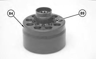
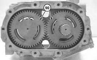
Illustration 16
17. Install springs (89) into barrel (84) .
g01200491
Illustration 17
18. Install retainer (88) onto barrel (84) .
Illustration 18
19. Install cap (87) onto barrel (84) .
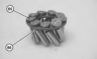
Illustration 19
20. Install pistons (85) into piston plate (86) .
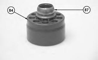
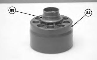
Illustration 20
g01200485
21. Install piston assembly (83) into barrel (84) .
22. Repeat Step 17 through Step 21 for the remaining barrel assembly.
Illustration 21
g01200482
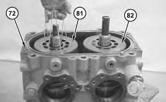
23. Install barrel assemblies (81) and (82) into pump housing (72) .
Note: It may be necessary to use string to aid in the removal procedure. The barrel assemblies must be installed in the original position during assembly.
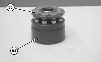
Illustration 22
24. Install O-ring seal (80) onto covers (78) .
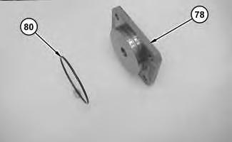
Illustration 23
25. Install covers (78) , bolts (77) , and plugs (79) onto pump housing (72) .
Illustration 24
26. Install O-ring seals (76) into pump housing (72) .
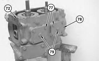
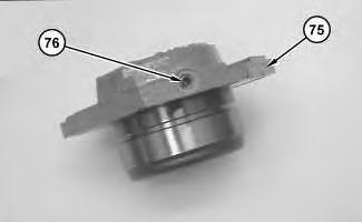
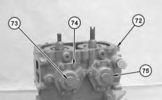
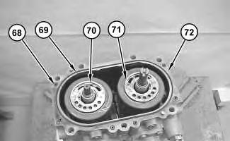 Illustration 25 g01200475
27. Install plug (76) into covers (75) .
Illustration 26 g01200473
Illustration 25 g01200475
27. Install plug (76) into covers (75) .
Illustration 26 g01200473
Illustration 27
29. Install O-ring seals (68) and (69) onto pump housing (72) . Install port plates (70) and (71) .
Note: The port plates must be installed in the original position during assembly.
Illustration 28
30. Install orifices (67) into head (58) .
Illustration 29
31. Install plugs (65) and (66) into head (58) .
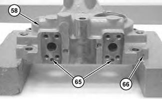
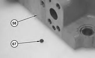
Illustration 30 g01201668
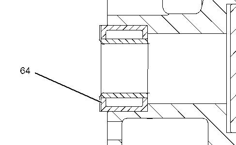 32. Install bearings (64) into the head.
Illustration 31 g01200459
32. Install bearings (64) into the head.
Illustration 31 g01200459
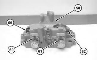
Illustration 32
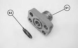
34. Install nipples (62) , covers (61) and bolts (60) onto head (58) . Install caps (59) onto nipples (62) .
Illustration 33
Personal injury can result from being struck by parts propelled by a released spring force.
Make sure to wear all necessary protective equipment.
Follow the recommended procedure and use all recommended tooling to release the spring force.
35. Attach Tooling (C) and a suitable lifting device to head (10) . Install head (58) , bolts (56) , and bolts (57) . The weight of head (58) is approximately 41 kg (90 lb).
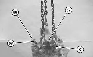
Illustration 34
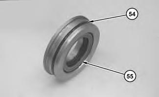
36. Install O-ring seal (54) and lip seal (55) onto the seal assembly.
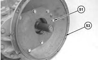
Illustration 35
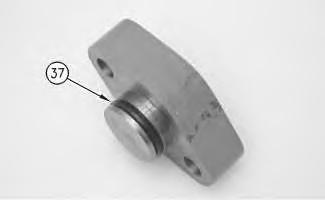
37. Install shrink wrap on the shaft. This will protect the seal during the installation procedure. Install the gasket and bell housing (53) . Install bolts (51) .
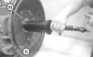
38. Use Tooling (D) to install seal assembly (52) .
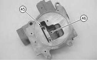
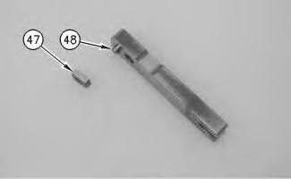
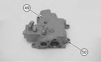
Illustration 37
g00706275
39. Install plugs (49) . Install three plugs (50) into the pump control.
Illustration 38
g00882609
40. Install slide plate (47) and dowel (48) onto the control linkage.
Illustration 39
41. Install control linkage (46) and sleeve (45) into the pump control.
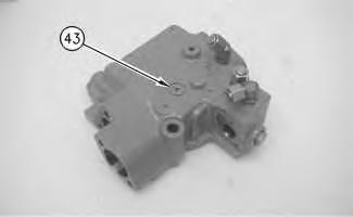
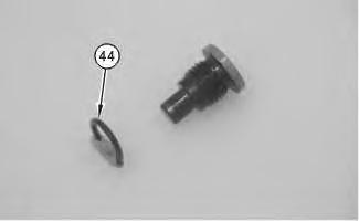
Illustration 40
42. Install O-ring seal (44) onto the pin.
Illustration 41
43. Install pin (43) into the pump control.
Personal injury can result from being struck by parts propelled by a released spring force.
Make sure to wear all necessary protective equipment.
Follow the recommended procedure and use all recommended tooling to release the spring force.
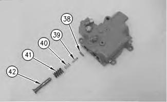
44. Install shims (38) , spool (39) , spring (40) , spring (41) , and control piston (42) into the pump control.
https://127.0.0.1/sisweb/sisweb/techdoc/techdoc_print_page.jsp?returnurl=/sisweb/sisw...
Illustration 42 g00882608 Illustration 43 g00706267Illustration 44
46. Install cover (36) onto the pump control. Install bolts (35) .
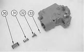
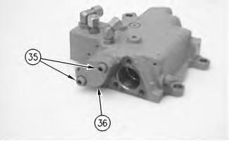
Illustration 45 g00706265
47. Install pilot piston (34) into the pump control.
Illustration 46 g00882601
Suggest:
If the above button click is invalid.
Please download this document first, and then click the above link to download the complete manual.
Thank you so much for reading

48. Install ball (33) into the guide. Install guide (32) into the pump control. Install spring (31) and spring (30) into the pump control.
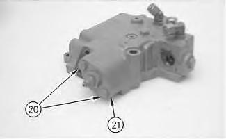
Illustration 47
g00882599
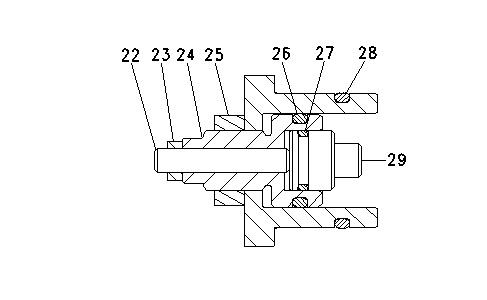
49. Install O-ring seal (26) onto the adjuster. Install adjuster (24) . Install setscrew (22) . Install nut (23) and nut (25) . Install O-ring seal (27) onto the retainer. Install retainer (29) . Install O-ring seal (28) .
Illustration 48
g00706249
Personal injury can result from being struck by parts propelled by a released spring force.
https://127.0.0.1/sisweb/sisweb/techdoc/techdoc_print_page.jsp?returnurl=/sisweb/sisw...