Service
Shutdown SIS
Previous Screen
Product: EXCAVATOR
Model: 330D MH EXCAVATOR LEM
Configuration: 330D Material Handler (HCR & FCR) LEM00001-UP (MACHINE) POWERED BY C9 Engine
Disassembly and Assembly
330D Excavator Machine Systems
Final Drive - Disassemble
SMCS - 4050-015
S/N - C5K1-222
S/N - LEM1-187
Disassembly Procedure
Required Tools
8T-0266 Bolt 1
Start By:
a. Remove the final drive and the travel motor. Refer to Disassembly and Assembly, "Final Drive and Travel Motor - Remove".
NOTICE
Care must be taken to ensure that fluids are contained during performance of inspection, maintenance, testing, adjusting, and repair of the product. Be prepared to collect the fluid with suitable containers before opening any compartment or disassembling any component containing fluids.
Refer to Special Publication, NENG2500, "Dealer Service Tool Catalog" for tools and supplies suitable to collect and contain fluids on Cat® products.
Dispose of all fluids according to local regulations and mandates.
Note: Cleanliness is an important factor. Before the disassembly procedure, the exterior of the component should be thoroughly cleaned. This will prevent dirt from entering the internal mechanism.
Note: Some of the images that are in this procedure do not show the sprocket assembly that is attached to the final drive housing. If necessary, the weights that are given include the weight of the sprocket assembly.
1. Put an alignment mark across the sections of the final drive for assembly purposes. The parts must be reinstalled to the original locations.
2. Fasten the final drive to Tooling (A). The weight of the final drive assembly is approximately 544 kg (1200 lb).
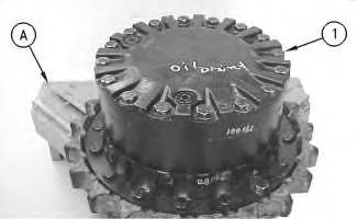
3. Remove bolts (1) that hold the cover in position.
Illustration 2
g00708090
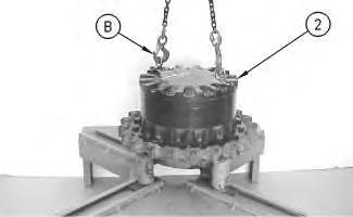
4. Remove the setscrews from the cover. Fasten Tooling (B) and a suitable lifting device to cover (2). Remove the cover. The weight of the cover is approximately 32 kg (70 lb).
Illustration 3
g00879362
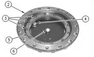
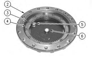
5. Remove bolts (3). Remove gear (5). Check plate (6). Replace plate (6) if wear is shown. Remove plugs (4) from cover (2).
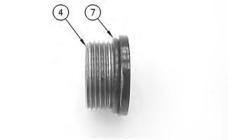
Illustration 4 g00879365
6. Remove O-ring seal (7) from plugs (4).
Illustration 5 g00780428
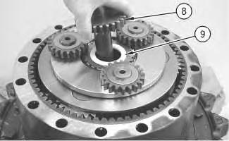
7. Remove gear (8). Remove spacer (9).
Illustration 6 g00780432
8. Use Tooling (C) to remove retaining ring (10). Remove washer (11). Remove gear (12). Remove bearing assembly (13). Remove second washer (11).
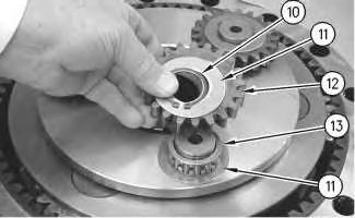
9. Repeat Step 8 for the remaining two gear assemblies.
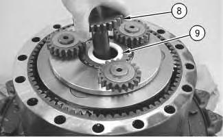
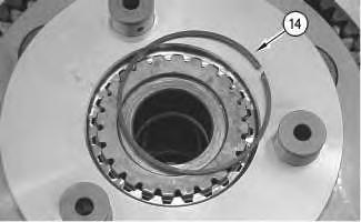
Illustration 7 g00781401
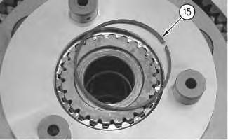
10. Remove retaining ring (14).
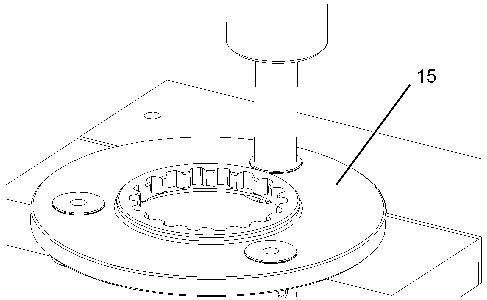
Illustration 8 g00781407
11. Remove carrier assembly (15).
Illustration 9 g01389593
12. Use a suitable press to remove the shafts from carrier assembly (15).

Illustration 10
13. Remove gear (16). Remove spacer (17).
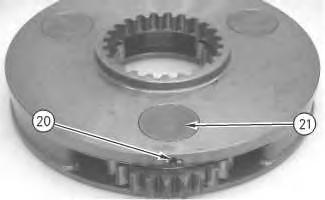
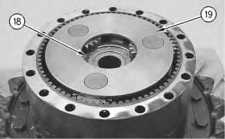
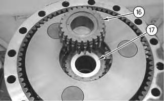
Illustration 11
14. Remove retaining ring (18).
15. Remove carrier assembly (19).
Illustration 12
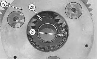
16. Disassemble carrier assembly (19), as follows.
a. Drive spring pin (20) into planetary shaft (21) with a hammer and a punch.
g00781412 g00781466 g00879368Illustration 13
b. Remove planetary shaft (21).
g00781476
c. Remove spring pin (20) from planetary shaft (21) with a hammer and a punch.
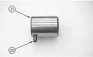
Illustration 14
g00781516
d. Remove thrust washers (22) and planetary gear (24) from the carrier assembly.
e. Remove bearing (23) from planetary gear (24).
17. Repeat Steps 16.a through 16.e for the other two planetary.
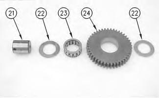
Illustration 15 g00781529
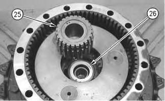
18. Remove gear (25). Remove spacer (26).
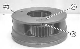
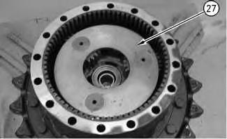
Illustration 16
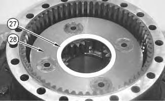
19. Remove carrier assembly (27).
20. Use two people to remove carrier assembly (27). The weight of the carrier assembly is approximately 38 kg (85 lb).
21. Disassemble carrier assembly (27), as follows.
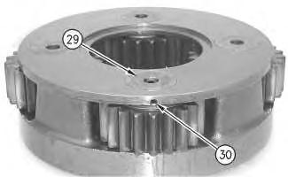
Illustration 17
a. Drive spring pin (29) into planetary shaft (28) with a hammer and a punch.
g00781559 g00781719Illustration 18
b. Remove planetary shaft (28).
g00781601
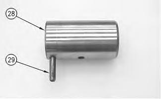
c. Remove spring pin (29) from planetary shaft (28) with a hammer and a punch.
Illustration 19
g00781607
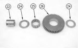
d. Remove thrust washers (30) and planetary gear (32) from the carrier assembly.
e. Remove two bearings (31) from the planetary gear.
22. Repeat Steps 21.a through 21.e for the other two planetary gears.
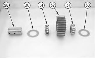 Illustration 20
g00781730
Illustration 20
g00781730
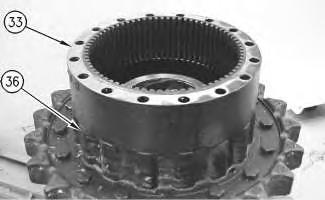
23. Use two people to remove gear (33). The weight of gear is approximately 41 kg (90 lb).
21
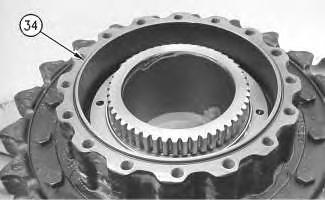
24. Remove O-ring seal (34).
Illustration 22
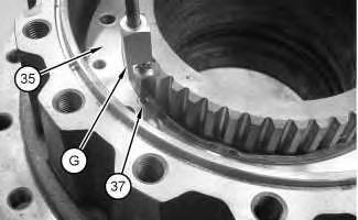
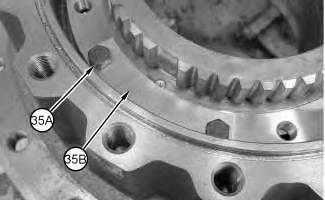
25. Remove bolts (35A) and plates (35B).
Illustration 23
26. Use Tooling (G) to remove dowel (37) from stopper plate assembly (35).
 Illustration
g00781807
g01147650
g01147651
Illustration
g00781807
g01147650
g01147651
Illustration 24
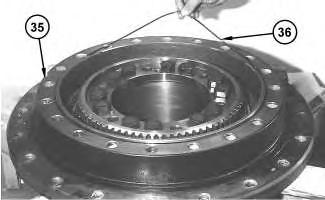
27. Secure Tooling (D) to stopper plate assembly (35). Use Tooling (D) to remove stopper plate assembly (35).
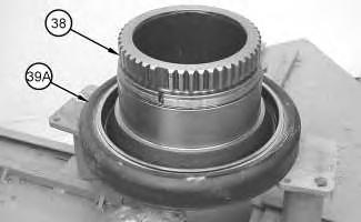
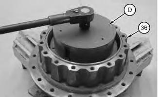
Illustration 25
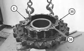
28. Use Tooling (E) and a suitable lifting device to remove housing (36). The weight of housing (36) is approximately 100 kg (220 lb).
29. Remove Duo-Cone seal (39A) from housing (38).
 g01147759
g01147930
Illustration 26
g01147951
g01147759
g01147930
Illustration 26
g01147951
Illustration 27
Illustration 28
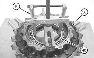
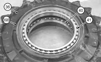
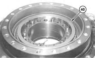
30. Remove Duo-Cone seal (39B) from housing (36).
31. Use Tooling (F) in order to remove bearings (40) and (41) from housing (36).
32. If necessary, remove the final drive sprocket from the sprocket housing. Refer to Disassembly and Assembly, "Final Drive Sprocket - Remove and Install". Copyright 1993 - 2020 Caterpillar Inc.
 g01147975
g01147934
g01147975
g01147934
Previous Screen
Product: EXCAVATOR
Model: 330D MH EXCAVATOR LEM
Configuration: 330D Material Handler (HCR & FCR) LEM00001-UP (MACHINE) POWERED BY C9 Engine
Disassembly and Assembly
330D Excavator Machine Systems
Final Drive - Disassemble
SMCS - 4050-015
S/N - C5K223-UP
S/N - LEM188-UP
S/N - PEL1-UP Disassembly
Start By:
A. Start by removing the final drive and the travel motor. Refer to Disassembly and Assembly, "Final Drive and Travel Motor - Remove".
Note: Cleanliness is an important factor. Before the disassembly procedure, the exterior of the component should be thoroughly cleaned. This will prevent dirt from entering the internal mechanism.
1. Put an alignment mark across the sections of the final drive for assembly purposes. The parts must be reinstalled to the original locations.
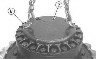
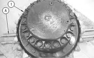
Illustration 1
2. Use Tooling (G) and a suitable lifting device to position the final drive assembly onto Tooling (A) . The weight of the final drive assembly is approximately 550 kg (1200 lb).
3. Remove bolts (1) .
Illustration 2
4. Use Tooling (B) and a suitable lifting device to remove cover (2) . The weight of cover (2) is approximately 32 kg (70 lb).
g00892878 g00892883Illustration 3 g00892888
5. Remove bolts (3) and gear (4) . Check plate (6) . Replace plate (6) if plate (6) is worn. Remove plugs (5) from cover (2) .
6. Remove O-ring seals (7) from plugs (5) .
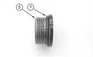 Illustration 4 g00892906
Illustration 5
g00892930
Illustration 4 g00892906
Illustration 5
g00892930
7. Remove gear (8) and spacer (9) .
8. Use Tooling (C) to remove retaining ring (10) . Remove washer (11) and gear (12) . Remove bearing assembly (13) and washer (14) .

9. Repeat Step 8 for the other two gear assemblies.
10. Remove retaining ring (15) .
Illustration 6 g00892965 Illustration 7 g00892968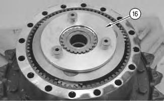
 Illustration 8 g00892975
11. Remove carrier assembly (16) .
Illustration 9 g01389804
12. Use a suitable press to remove the shafts from carrier assembly (16) .
Illustration 8 g00892975
11. Remove carrier assembly (16) .
Illustration 9 g01389804
12. Use a suitable press to remove the shafts from carrier assembly (16) .
13. Remove gear (17) and spacer (18) .
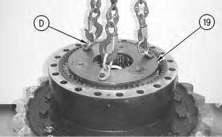
14. Use Tooling (D) and a suitable lifting device to remove planetary carrier (19) . The weight of planetary carrier (19) is approximately 48 kg (105 lb).
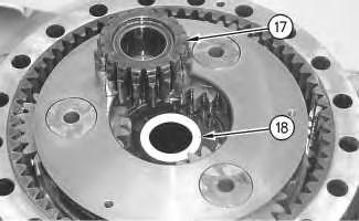 Illustration 10
g00892977
Illustration 11
g00892997
Illustration 12
g00893019
Illustration 10
g00892977
Illustration 11
g00892997
Illustration 12
g00893019
15. Remove retainer ring (21) . Lift planetary carrier (19) off sun gear (20) .
Illustration 13 g00896860
16. Drive spring pin (23) into planetary shaft (22) .
Illustration 14 g00893043
17. Remove planetary shaft (22) . Use a suitable punch to remove spring pin (23) from planetary shaft (22) .
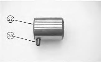
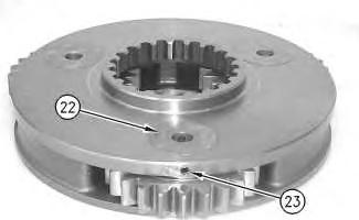
Illustration 15
g00896863
18. Remove washers (24) and bearing (25) from planetary gear (26) .
19. Repeat Steps 16 through 18 for the other two planetary gears.
Illustration 16
20. Remove spacer (27) .
g00897431
21. Use two people to remove carrier assembly (28) . The weight of carrier assembly (28) is approximately 38 kg (85 lb).
Illustration 17
22. Drive spring pin (30) into shaft (29) .
Illustration 18
23. Remove shaft (29) . Use a suitable punch to remove spring pin (30) from shaft (29) .
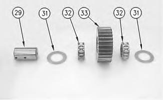
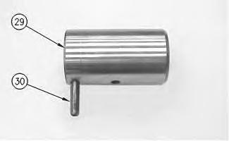
Illustration 19 g00893674
24. Remove washers (31) and bearings (32) from planetary gear (33) .
25. Repeat Steps 22 through 24 for the other three planetary gears.
26. Fasten Tooling (E) and a suitable lifting device to ring gear (34) , as shown. Remove ring gear (34) from sprocket housing (35) . The weight of ring gear (34) is approximately 66 kg (146 lb).
27. Remove O-ring seal (36) from sprocket housing (35) .
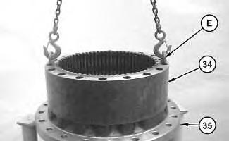 Illustration 20 g01208300
Illustration 21 g01208542
Illustration 20 g01208300
Illustration 21 g01208542
Illustration 22
g01208553
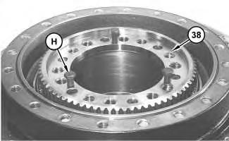
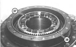
28. Remove bolts (37) from coupling gear (38) .
Illustration 23
g01898713
Note: Mark the orientation of coupling gear (38) for assembly purposes.
29. Install Tooling (H) in coupling gear (38) . Tighten Tooling (H) evenly in order to loosen coupling gear (38) . Remove the coupling gear from the motor housing.
Suggest:
If the above button click is invalid.
Please download this document first, and then click the above link to download the complete manual.
Thank you so much for reading

30. Remove shims (40) from the motor housing.
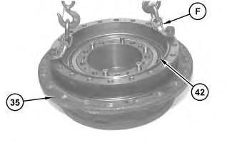
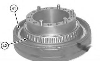
Note: Inner cones and outer bearing cones (42) are a slip fit on the motor housing. While you remove sprocket housing (35) from the motor housing, inner bearing cone (42) may stay with the sprocket housing or the inner bearing cone may stay on the motor housing.
31. Fasten Tooling (F) and a suitable lifting device to sprocket housing (35) . Separate the sprocket housing from the motor housing. The weight of sprocket housing (35) is 109 kg (240 lb).
32. Remove the locating pins from the motor housing.
33. Remove Duo-Cone seal (41) from the motor housing.
34. If inner bearing cone (42) remained on the motor housing, then remove the inner bearing cone.