
Shutdown SIS
Previous Screen
Product: MOBILE HYD POWER UNIT
Model: 330D L MOBILE HYD POWER UNIT H3D
Configuration: 330D L Mobile Hydraulic Power Unit H3D00001-UP (MACHINE) POWERED BY C9 Engine
Disassembly and Assembly
C9 Engines for Caterpillar Built Machines
Gear Group (Rear) - Remove and Install
SMCS - 1206-010; 1212-010
Removal Procedure Table 1
Required Tools
Start By:
A. Remove the flywheel and pump drive gear. Refer to Disassembly and Assembly, "Flywheel - Remove".
NOTICE
Keep all parts clean from contaminants.
Contaminants may cause rapid wear and shortened component life.
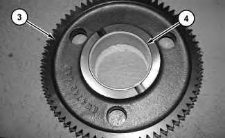
1. Remove bolts (1) and remove retainer (2). Remove gear assembly (3) .
2. Use Tooling (A) in order to remove bushing (4) from gear assembly (3) .

3. Repeat Steps 1 and 2 for the opposite side.
 Illustration 1
g01383883
Illustration 2
g01383924
Illustration 3
g01383927
Illustration 1
g01383883
Illustration 2
g01383924
Illustration 3
g01383927
4. Remove bolts (5). Remove adapter (6) and the O-ring seal.
5. Use Tooling (B) in order to remove bearing (7) from adapter assembly (6) .


6. Remove gear assembly (8) .
 Illustration 4 g01384414
Illustration 5 g01384424
Illustration 4 g01384414
Illustration 5 g01384424
Illustration 6 g01384430
7. Remove cover (9) and the O-ring seal.
Illustration 7 g01384432
8. Use Tooling (B) in order to remove bearing (10) .

9. Repeat Steps 4 through 8 for the opposite side.
Installation Procedure
NOTICE
Keep all parts clean from contaminants.
Contaminants may cause rapid wear and shortened component life.
1. Lower the temperature of bearing (10). Be sure to match Dimension (B) and Dimension (C) when you are installing bearing (10). Dimension (B) indicates the angle of the joint on bearing (10). Dimension (B) is 15° ± 1°. Dimension (C) shows the distance from bearing (10) to the end of the bore. Dimension (C) is 4.000 ± 0.500 mm (0.1575 ± 0.0197 inch).


2. Lower the temperature of bearing (10A). Be sure to match Dimension (D) and Dimension (E) when you are installing bearing (10A). Dimension (D) indicates the angle of the joint on bearing (10A). Dimension (D) is 15° ± 1°. Dimension (E) shows the distance from bearing (10A) to the end of the bore. Dimension (E) is 4.000 ± 0.500 mm (0.1575 ± 0.0197 inch).

 Illustration

 Illustration 13 g01384430
3. Install the O-ring seal and cover (9) .
Illustration 14 g01384783
4. Install gear assembly (8). Be sure that oil passage plug (8A) is facing outward.
Illustration 15
g01384809
Illustration 13 g01384430
3. Install the O-ring seal and cover (9) .
Illustration 14 g01384783
4. Install gear assembly (8). Be sure that oil passage plug (8A) is facing outward.
Illustration 15
g01384809
Illustration 16
g01384831
5. Lower the temperature of bearing (7). Be sure to match Dimension (F) and Dimension (G) when you are installing bearing (7) into adapter assembly (6). Dimension (F) indicates the angle of the joint on bearing (7). Dimension (F) is 15° ± 1°. Dimension (G) shows the distance from bearing (7) to the end of the bore. Dimension (G) is 3.500 ± 0.500 mm (0.1378 ± 0.0197 inch).
Illustration 17
g01383927
6. Install the O-ring seal and adapter assembly (6). Install bolts (5) .
7. Repeat Steps 3 through 6 for the opposite side.

Illustration 18
g01384996
8. Lower the temperature of bearing (4). Install bearing (4) into gear assembly (3). Be sure that each relief (H) in bearing (4) is within 2° of each relief in gear assembly (3) .
Illustration 19
g01383883
9. Position gear assembly (3) and retainer (2). Install bolts (1) .
10. Repeat Steps 8 and 9 for the opposite side.
End By: Install the flywheel and pump drive gear. Refer to Disassembly and Assembly, "Flywheel - Install".

Copyright 1993 - 2020 Caterpillar Inc.
All Rights Reserved.
Private Network For SIS Licensees.
Shutdown SIS
Previous Screen
Product: MOBILE HYD POWER UNIT
Model: 330D L MOBILE HYD POWER UNIT H3D
Configuration: 330D L Mobile Hydraulic Power Unit H3D00001-UP (MACHINE) POWERED BY C9 Engine
Disassembly and Assembly
C9 Engines for Caterpillar Built Machines
Flywheel - Remove
SMCS - 1156-011
Removal Procedure Table 1
Required Tools
Illustration 1
1. Remove bolts 180 degrees apart. Install Tooling (A). Remove the remaining bolts (1).
Illustration 2
2. Fasten a suitable lifting device to flywheel (2). The weight of flywheel (2) is approximately 60 kg (130 lb).

 g02711645
g02711621
g02711645
g02711621
3. Remove flywheel (2).
4. Use a hammer and a punch in order to remove the flywheel ring gear, if necessary.
5. Remove the pump drive gear, if necessary.
Shutdown SIS
Previous Screen
Product: MOBILE HYD POWER UNIT
Model: 330D L MOBILE HYD POWER UNIT H3D
Configuration: 330D L Mobile Hydraulic Power Unit H3D00001-UP (MACHINE) POWERED BY C9 Engine
Disassembly and Assembly
C9 Engines for Caterpillar Built Machines
Flywheel - Install
SMCS - 1156-012
Installation Procedure Table 1
Required Tools
243 -
1. Install the pump drive gear, if necessary.
2. Raise the temperature of the flywheel ring gear. Do not use a torch to heat the flywheel ring gear. Install the flywheel ring gear on the flywheel. Position the flywheel ring gear with the part number toward the crankshaft. Allow the flywheel ring gear to cool. Use a soft hammer to seat the flywheel ring gear against the shoulder of the flywheel.
g02711621
3. Attach a suitable lifting device to flywheel (2). The weight of flywheel (2) is approximately 60 kg (130 lb).
g02711645
Illustration 1
Illustration 2
4. Position flywheel (2) on Tooling (A).
Note: When reusing bolts (1), apply Tooling (B) to the threads.
5. Install bolts (1). Remove Tooling (A) and install remaining bolts (1). Tighten bolts evenly to a torque of 300 ± 40 N·m (221 ± 30 lb ft).
6. Check the flywheel runout. Refer to Testing and Adjusting, "Flywheel - Inspect".
Shutdown SIS
Previous Screen
Product: MOBILE HYD POWER UNIT
Model: 330D L MOBILE HYD POWER UNIT H3D
Configuration: 330D L Mobile Hydraulic Power Unit H3D00001-UP (MACHINE) POWERED BY C9 Engine
Disassembly and Assembly
C9 Engines for Caterpillar Built Machines
Crankshaft Rear Seal - Remove
SMCS - 1161-011
Removal Procedure
Start By:
A. Remove the flywheel. Refer to Disassembly and Assembly, "Flywheel - Remove".
NOTICE
Care must be taken to ensure that fluids are contained during performance of inspection, maintenance, testing, adjusting, and repair of the product. Be prepared to collect the fluid with suitable containers before opening any compartment or disassembling any component containing fluids.
Refer to Special Publication, NENG2500, "Dealer Service Tool Catalog" for tools and supplies suitable to collect and contain fluids on Cat products.
Dispose of all fluids according to local regulations and mandates.
Illustration 1
1. Remove bolts (2) .

2. Remove crankshaft rear seal (1) from the crankshaft.
g01140085
Note: Refer to Reuse and Salvage Guidelines, SEBF8039, "Crankshaft Visual Inspection and Magnetic Particle Inspection" for the correct inspection procedure of the crankshaft seal surface.
Note: Refer to Reuse and Salvage Guidelines, SEBF9217, "Specifications for Crankshafts C7, C9, C-9, C10, C11, C12, C-12, C13, C-13, C15, C-15, C18, C-18, C27, C30, and C32 Engines" or the correct specifications of the crankshaft.
Copyright 1993 - 2020 Caterpillar Inc.
All Rights Reserved. Private Network For SIS Licensees.
Previous Screen
Product: MOBILE HYD POWER UNIT
Model: 330D L MOBILE HYD POWER UNIT H3D
Configuration: 330D L Mobile Hydraulic Power Unit H3D00001-UP (MACHINE) POWERED BY C9 Engine
Disassembly and Assembly
C9 Engines for Caterpillar Built Machines
Crankshaft Rear Seal - Install
SMCS - 1161-012
Installation Procedure Table 1
Required Tools
NOTICE
Keep all parts clean from contaminants.
Contaminants may cause rapid wear and shortened component life.
Shutdown SIS
Illustration 2
Numerical tightening sequence for bolts (2).

Note: If required, install a crankshaft wear sleeve at engine overhaul. For more information please refer to the following Reuse and Salvage Guidelines. Refer to Reuse and Salvage Guidelines, SEBF9217, "Specifications for Crankshafts C7, C9, C-9, C10, C11, C12, C-12,
Illustration 1 g01140085
g03698745
C13, C-13, C15, C-15, C18, C-18, C27, C30, and C32 Engines" or the correct specifications of the crankshaft. Refer to Reuse and Salvage Guidelines, SEBF8039, "Crankshaft Visual Inspection and Magnetic Particle Inspection" for the correct inspection procedure of the crankshaft seal surface.
1. If a crankshaft wear sleeve is necessary, refer to Step 1.a through Step 1.d to install the crankshaft wear sleeve. If a crankshaft wear sleeve is not necessary, refer to Step 2.
a. Clean and polish the crankshaft of imperfections.
b. Use Tooling (A) to clean the outside diameter of the crankshaft and the inside diameter of the crankshaft wear sleeve.
c. Apply Tooling (B) to the outside diameter of the crankshaft and the inside diameter of the crankshaft wear sleeve.
d. Use Tooling (C) to install the crankshaft wear sleeve.
Note: Leave the shipping sleeve in place to install the crankshaft rear seal. The crankshaft rear seal must be installed dry.
Note: If the seal group, O-ring seal, and the shipping sleeve are separated, these components should not be used.
2. Lubricate the O-ring seal with clean engine oil that is on the back of the crankshaft rear seal (1).
3. Position crankshaft rear seal (1) and the shipping sleeve over the crankshaft. Push crankshaft rear seal (1) in place. This will dislodge the shipping sleeve.
Note: Do not remove the shipping sleeve until bolts (2) are installed.
4. Install new bolts (2) hand tight. Then, tighten bolts (2) in numerical sequence, shown in Illustration 2. Tighten bolts (2) to a torque of 12 ± 3 N·m (106 ± 27 lb in).
End By:
a. Install the flywheel. Refer to Disassembly and Assembly, "Flywheel - Install".
Shutdown SIS
Previous Screen
Product: MOBILE HYD POWER UNIT
Model: 330D L MOBILE HYD POWER UNIT H3D
Configuration: 330D L Mobile Hydraulic Power Unit H3D00001-UP (MACHINE) POWERED BY C9 Engine
Disassembly and Assembly
C9 Engines for Caterpillar Built Machines
Flywheel Housing - Remove and Install
SMCS - 1157-010
Removal Procedure Table 1
Required Tools
Tool Part Number Part Description Qty
A 138-7575 Link Bracket 2
Start By:
a. Remove the flywheel. Refer to Disassembly and Assembly, "Flywheel - Remove".
b. Remove the electric starting motor. Refer to Disassembly and Assembly, "Electric Starting Motor - Remove and Install".
Illustration 1
g01151394
1. Attach Tooling (A) and a suitable lifting device onto flywheel housing (1). The weight of flywheel housing (1) is approximately 37 kg (82 lb).

2. Remove bolts (2). Remove bolts (3).
3. Remove bolts (4) (not shown) that fasten the engine oil pan to flywheel housing (1). Remove flywheel housing (1).
Installation Procedure
Table 2
Required Tools Tool
A 138-7575 Link Bracket 2
B 1U-8846 Gasket Sealant 1
1. Apply Tooling (B) to the entire mounting surface of the flywheel housing prior to installation.
Suggest:
If the above button click is invalid.
Please download this document first, and then click the above link to download the complete manual.
Thank you so much for reading

Illustration 2
g01151394
2. Attach Tooling (A) and a suitable lifting device onto flywheel housing (1). The weight of flywheel housing (1) is approximately 37 kg (82 lb). Position flywheel housing (1) on the engine block.
3. Install bolts (2). Install bolts (3).
4. Install bolts (4) (not shown) that fasten the engine oil pan to flywheel housing (1).
End By:
a. Install the electric starting motor. Refer to Disassembly and Assembly, "Electric Starting Motor - Remove and Install".
b. Install the flywheel. Refer to Disassembly and Assembly, "Flywheel - Install".
Copyright 1993 - 2020 Caterpillar Inc. All Rights Reserved. Private Network For SIS Licensees.
Wed Jul 29 22:32:57 UTC+0800 2020