Shutdown SIS
Previous Screen
Product: EXCAVATOR
Model: 330D L EXCAVATOR MWP
Configuration: 330D L Excavator MWP00001-UP (MACHINE) POWERED BY C9 Engine
Disassembly and Assembly
330D, 336D, 336D2, 340D and 340D2 Excavators and 336D MHPU Mobile Hydraulic Power Unit Machine Systems
Final Drive - Disassemble
SMCS - 4050-015
S/N - GGH1-UP
S/N - MWP1-UP
S/N - NBN1-UP
Disassembly Procedure
Table 1
Required Tools
(1) Use 6C-7887 Leg on the two gears that are removed in Step 22.
(2) Part of Tooling (Q)
Start By:
a. Remove the final drive. Refer to Disassembly and Assembly, "Final Drive - Remove".
1. Thoroughly clean the outside of the final drive and travel motor prior to disassembly.
2. Remove bolts (2) that hold travel motor (1) to the final drive.
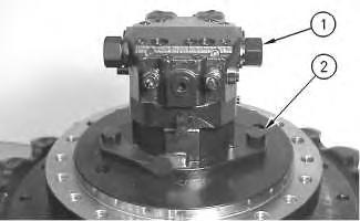
3. Fasten two suitable lifting straps and a suitable lifting device to travel motor (1). The weight of travel motor (1) is approximately 54 kg (120 lb). Carefully remove travel motor (1) from the final drive.
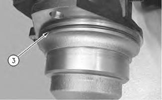
4. Remove O-ring seal (3) from the travel motor.
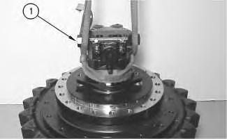 Illustration 1
g00659659
Illustration 2
g00659674
Illustration 3
g00676009
Illustration 1
g00659659
Illustration 2
g00659674
Illustration 3
g00676009
5. Fasten Tooling (A) and a suitable lifting device to the final drive, and turn the final drive on the side. The weight of the final drive is 500 kg (1100 lb).

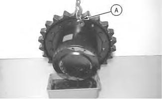
6. Remove plug (4).
NOTICE
Care must be taken to ensure that fluids are contained during performance of inspection, maintenance, testing, adjusting, and repair of the product. Be prepared to collect the fluid with suitable containers before opening any compartment or disassembling any component containing fluids.
Refer to Special Publication, NENG2500, "Dealer Service Tool Catalog" for tools and supplies suitable to collect and contain fluids on Cat products.
Dispose of all fluids according to local regulations and mandates.
Illustration 4 g00659679 Illustration 5 g006596827. Drain the oil from the final drive into a suitable container for storage or disposal. Refer to Operation and Maintenance Manual, "Capacities (Refill)" for the capacity. Refer to Operation and Maintenance Manual, "Final Drive Oil - Change" for the proper procedure.
8. Reinstall plug (4).
9. Position the final drive onto suitable blocking, as shown.
10. Remove the sprocket bolts (5) from final drive sprocket (6).
11. Use a suitable lifting device to remove final drive sprocket (6). If necessary, use a soft faced hammer in order to unseat the sprocket.
12. The weight of the final drive sprocket is 91 kg (200 lb).
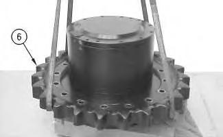
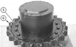 Illustration 6 g00659729
Illustration 7 g00659738
Illustration 6 g00659729
Illustration 7 g00659738
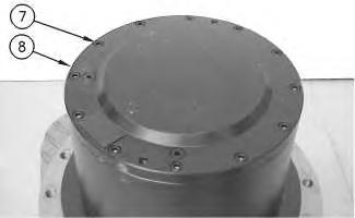
13. Remove bolts (7) that hold cover (8) in place.
14. Use Tooling (T) to elevate cover (8). This will allow enough clearance for your fingers in order to lift cover (8) off the final drive.
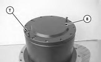
15. Remove cover (8).
16. If necessary, remove the spacer (Not Shown) from cover (8).
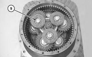
Illustration 8 g00659746 Illustration 9 g01391477 Illustration 10 g0139149017. Remove carrier assembly (9).
18. Disassemble carrier assembly (9), as follows:
Illustration 11 g01391499
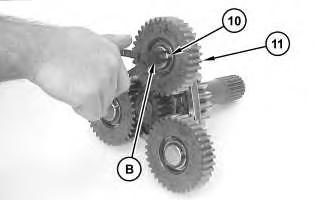
a. Use Tooling (B) to remove retaining ring (10).
Illustration 12 g01391503
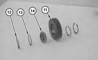
b. Use a soft faced hammer in order to remove planetary gear assembly (11).
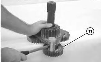
Note: Rotate the planetary gear assembly so that the gear assembly comes off perpendicular to the carrier shaft.
c. Disassemble planetary gear assembly (11), as follows.
d. Use Tooling (C) to remove the second retaining ring (12).
Note: When you remove the bearing assembly, the rollers will fall out of the bearing race. Put a rubber band around the bearing rollers as you remove the bearing assembly.
e. Remove two rings (13), and bearing (13) from planetary gear assembly (11).
f. Repeat Steps 18.a through 18.e for the other two planetary gears.
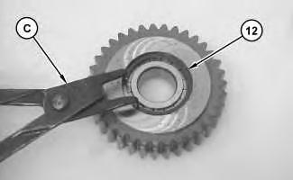 Illustration 13
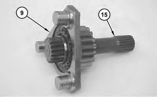
g. Remove center shaft (15) from carrier assembly (9).
Illustration 16 g01391515
h. Use a hammer and a punch to remove washer (16) from center shaft (15).
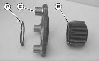
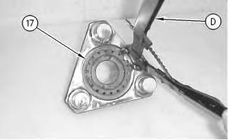
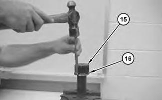
Illustration 17 g00659844
Illustration 18 g00659863
i. Use Tooling (D) in order to remove retaining ring (17).
j. Remove sun gear (18) from carrier assembly (10).
Illustration 19
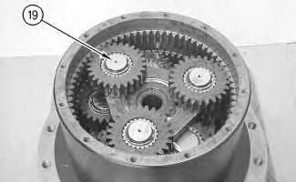
19. Remove carrier assembly (19).
20. Disassemble carrier assembly (19), as follows:
Illustration 20
Illustration 21
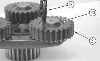
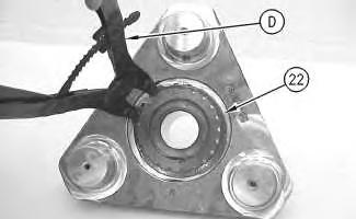
a. Use Tooling (D) to remove retaining ring (20).
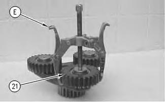
b. Use Tooling (E) in order to remove planetary gear assembly (21).
 g00659867
g00659873
g00659879
g00659867
g00659873
g00659879
c. Use Tooling (F) and a suitable press in order to drive the bearing assembly out of planetary gear (21).
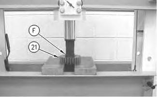
Note: This is only one method for removing the bearing. You may also cut the bearing. Make sure that you catch the rollers, while you drive the bearing assembly out of planetary gear (21).
d. Repeat Steps 20.a through 20.c for the other two planetary gear assemblies.
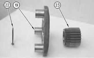
Illustration 22 g00659889 Illustration 23 g00660095 Illustration 24 g00660100e. Use Tooling (D) in order to remove retaining ring (22).
f. Remove sun gear (23) from carrier assembly (19).
21. Use Tooling (D) in order to remove two retaining rings (26) from two of the planetary gear assemblies (24) from carrier assembly (25).
Note: There are two sets of bearing rollers for each planetary gear assembly. The bearing rollers for the lower bearing assembly will fall after the planetary gear assembly is removed.
22. Use Tooling (E) in order to remove two planetary gear assemblies (24).
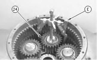
Note: Two planetary gear assemblies (24) are removed in order to access the retaining ring that holds the carrier assembly (25) to the motor housing.
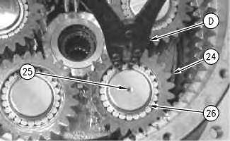 Illustration 25 g00660105
Illustration 26
g00660136
Illustration 25 g00660105
Illustration 26
g00660136
23. Use Tooling (G) in order to remove retaining ring (27).
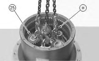
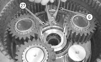
24. Use Tooling (H) and a suitable lifting device to remove carrier assembly (25).
25. Disassemble carrier assembly (25), as follows:
a. Use Tooling (E) to remove bearing race (28) from the two shafts of carrier assembly (25).
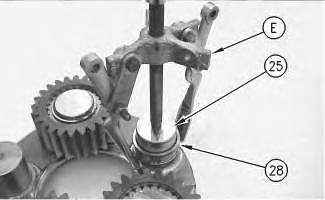 Illustration 27 g00660143
Illustration 28 g00660173
Illustration 29 g00765592
Illustration 27 g00660143
Illustration 28 g00660173
Illustration 29 g00765592
b. Use Tooling (D) to remove three retaining rings (26) from the three remaining planetary gear assemblies.
c. Use Tooling (E) to remove planetary gear assemblies from the carrier assembly.
d. Use Tooling (E) to remove the other three bearing races from the carrier assembly.
Note: Refer to Illustration 26 for the location of planetary gear assemblies (24).
e. Disassemble planetary gear assemblies (24), as follows.
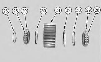
f. Remove bearing rollers (29), two bearing races (28), two rings (30), and retaining ring (32) from planetary gear (31).
Note: Place a rubber band around the bearing rollers as you remove the bearings.
26. Attach a suitable lifting device to the final drive, and turn the final drive over 180 degrees.
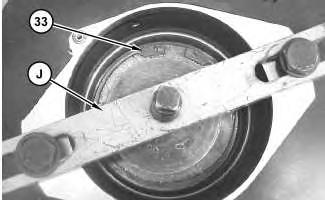
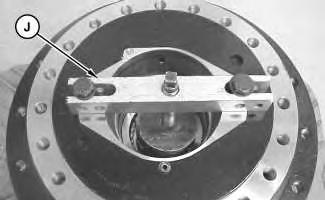
Illustration 30 g00660181 Illustration 31 g01393288Sudden release of spring force can cause injury. To prevent the possibility of injury, follow the procedure to relieve the spring pressure.
27. Tighten Tooling (J) in order to relieve the spring pressure.
28. Use Tooling (K) in order to remove retaining ring (33).

29. Slowly release Tooling (J). Remove Tooling (J).
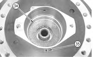
30. Remove plate (34).
31. Remove plug (35).
Illustration 32 g01393292 Illustration 33 g0066022632. Remove springs (36).
Note: There is an inner spring and a outer spring in each spring set.
33. Loosely install Tooling (J) so that piston (37) can vertically travel during the application of air pressure. Apply air pressure through the port of plug (35). Hold a finger over the port directly across plug (35) while you inject the air. This will unseat the brake piston (37).
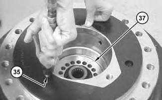
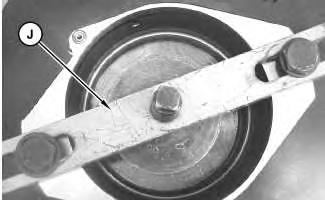
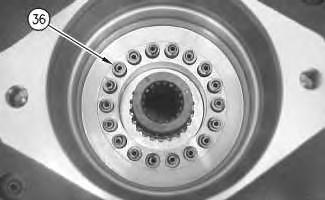 Illustration 34
g00660233
Illustration 35
g01393295
Illustration 36
g01393340
Illustration 34
g00660233
Illustration 35
g01393295
Illustration 36
g01393340
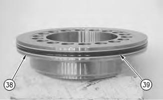
34. Remove brake piston (37).
35. Remove two backup rings (38) and O-ring seal (39) from the piston.
36. Attach a suitable lifting device to the final drive, and turn the final drive over 180 degrees in order for the discs and plates to fall out of the motor housing.
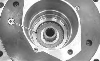
37. Remove discs and plates (40) from the motor housing.
Note: Note the orientation of the discs and the plates for installation purposes.
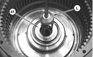
Illustration 37 g00660245 Illustration 38 g00660451Illustration 39 g01393395
38. Use Tooling (L) to remove washer (41).
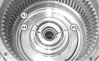
Illustration 40 g01393399
39. Use Tooling (K) to remove retaining ring (42).
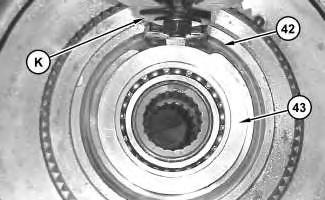
Note: Tap on plate (43) in order to relieve the pressure that is on retaining ring (42).
Illustration 41 g00660488
Illustration 42 g01393402
40. Attach a suitable lifting device to the final drive, and turn the final drive over 180 degrees, as shown.
41. Use Tooling (J) in order to remove coupling shaft (45), bearing (44), and plate (43).
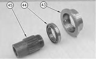
Illustration 43 g00660550
Illustration 44
g00660508
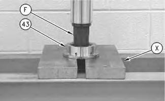
42. Disassemble coupling shaft (45), bearing (44), and plate (43), as follows.
a. Use Tooling (F) and a suitable press in order to push the coupling shaft (45) through bearing (44) and plate (43).
Note: Bearing (44) will stop once the bearing makes contact with the Plates (X).
g00660671
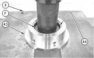
Note: Spread Plates (X) wide enough so that bearing (44) can be removed from plate (43).
b. Use Tooling (F) and a suitable press in order to push bearing (44) out of plate (43).

g00660479
43. Drill out two dowels (47) in order to remove locknut (46).
127-8458 Final Drive Disassembly and Assembly Bench
Note: The following procedure is for using the final drive disassembly and assembly 127-8458 Bench.
Note: Tooling (QQ) is part of the 127-8458 Final Drive Bench Ar.
Reference: Refer to the Tool Operating Manual, NEHS0673 for further procedures concerning 127-8458 Bench.
Illustration 45 Illustration 46 (U) Notches for Tooling (N)1. Fasten Tooling (M) and a suitable lifting device to Tooling (N).
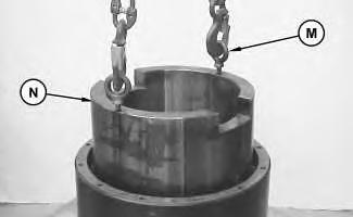
Note: Refer to Illustration 46 for the location of notches (U) in nut (46).
2. Lower Tooling (N) into the final drive. Make sure that the notches in nut (46) are aligned with the keys on Tooling (N). The approximate weight of Tooling (N) is 45 kg (100 lb).
3. Fasten Tooling (P) and a suitable lifting device to the final drive. Keep the suitable lifting device attached.
4. Position the final drive on Tooling (QQ).
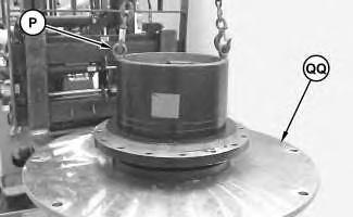 Illustration 47 g01393415
Illustration 48 g01393436
Illustration 47 g01393415
Illustration 48 g01393436
Illustration 49
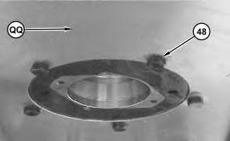
5. Raise the final drive and Tooling (QQ) into the air so that you can bolt the final drive and Tooling (QQ) together with bolts (48).
Note: Place blocks under Tooling (QQ) while you tighten bolts (48).
Illustration 50
6. Remove the suitable lifting device from Tooling (P) and attach four chains and a suitable lifting device to the upper half of Tooling (Q).
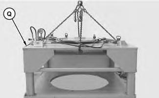
7. Remove the upper half of Tooling (Q). The weight of the upper half is 816 kg (1800 lb).
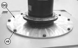
Illustration 51
8. Install Tooling (P) and a suitable lifting device to Tooling (QQ). Place Tooling (QQ) and the final drive onto the lower half of Tooling (Q). The weight of the final drive, Tooling (QQ), and Tooling (N) is 522 kg (1150 lb).
9. Fasten the final drive onto the lower half of Tooling (Q). Use eight 1 - 8THDX3.5 inch bolts (49) and eight 1 - 8THD nuts with washers.
10. Remove Tooling (P) and the suitable lifting device.
Illustration 52 g01393962
11. Place Tooling (R) into the final drive.
12. Fasten a suitable lifting device to the upper half of Tooling (Q) and install the upper half of Tooling (Q) to the lower half of Tooling (Q). Pin the two halves together.
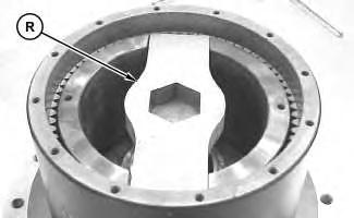
Illustration 53 g01394025
13. Attach Tooling (S) to the pressure reducing valve manifold, as shown.
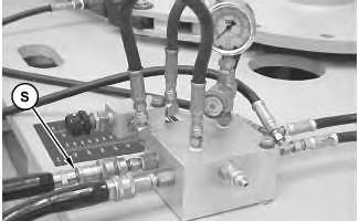
14. Set the torque level for the bench to 2000 psi (14500 lb ft). Do not exceed this pressure.
Reference: Refer to the Tool Operating Manual, NEHS0673 for setting the torque level.
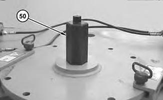
Illustration 54
(50) 128-4075 Shaft As
g01394027
15. Place hex shaft (50) through the bench and into Tooling (R).
16. Remove locknut (46). The breakaway torque will vary. The nut will loosen usually at 1400 psi (10750 lb ft).
17. Fasten a suitable lifting device to the upper half of Tooling (Q).
18. Remove the upper half of Tooling (Q).
Disassembly Procedure for the Main Housing and the Motor Housing
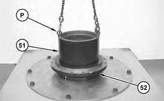
Illustration 55
g01394031
1. Fasten Tooling (P) and a suitable lifting device to main housing (51), as shown.
2. Separate main housing (51) from motor housing (52). The weight of main housing (51) is approximately 204 kg (450 lb).
Note: Two outer races and one roller bearing will be removed with the main housing. The other roller bearing and the two Duo-cone seal kits will remain with the motor housing.
3. Disassemble motor housing (52), as follows.
Suggest:
If the above button click is invalid.
Please download this document first, and then click the above link to download the complete manual.
Thank you so much for reading

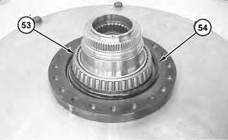
Illustration 56
a. Remove bearing cone (53) from the motor housing.
b. Remove the Duo-Cone seal kit (54) from the motor housing.
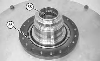
Illustration 57
c. Remove the two backup rings and O-ring seal (55) from the motor housing.
d. Remove the other Duo-Cone seal kit (56) from the motor housing.
4. Disassemble main housing (51), as follows.
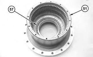
Illustration 58
a. Remove bearing cone (57) from main housing (51).