

1 Working with the Waves: How Small-scale, Wavepowered Innovations Support a Sustainable Ocean

65 Stored Energy in the Sea: Combining 3D Printed Pumped Hydro Energy Storage Systems with Floating Offshore Wind in California
Christian Dick, Jonas Sprengelmeyer
Fraunhofer IEE
Gabriel Falzone
RCAM Technologies
74 Making Better Blades for Tidal Energy Generation
Javier Grande, Marta Garcia, Pablo Carpintero
Magallanes Renovables
Adrián Delgado, Chloe Richards, Fiona Regan
Dublin City University
Peer-Reviewed Papers
84 Integration of Wave Energy Devices with Chambered Breakwater
K. Aiswaria, Balaji Ramakrishnan
Indian Institute of Technology Debarshi Sarkar
Jadavpur University
…
Ruiqi
Tony Lewis
OceanEnergy
Lars
53 EuropeWave: Bridging the Gap to Commercialization of Wave Energy Technology using Pre-commercial Procurement
Peter Dennis
Wave Energy Scotland


Cameron McNatt, Mocean Energy
Whitney Berry, Ocean Conservancy
Angie Bishop
The Journal of Ocean Technology, Vol. 18, No. 1, 2023 i Copyright Journal of Ocean Technology 2023 ii Editorial Board iii On the Cover iv Publishing Schedule and Advertisements v Guest Editor’s Note from John Risley
Essays
Jane Blinkenberg, Per Resen Steenstrup Resen Waves
the
of the
with Green
Leet World Energy GH2
Regenerative
Seawater Industries Powered by OTEC Benjamin Martin Xenesys Inc. 26 Blue Energy from Salinity Gradients
Oostrom REDstack BV
13 Green Shipping Corridors are Becoming a Reality: Speeding up
Decarbonization
Maritime Industry
Ammonia Sean
18
Island Infrastructure:
Joost Veerman, Pieter Hack, Rik Siebers, Michael van
38 Holding a Spermaceti Candle to the Wind of New Technology
the
Keith Alverson Fong Ku Alberta University of
Arts 42 WEDUSEA: Creating a Step Change for the Wave Energy Industry
Johanning University of Exeter
Contents
Melo 107 Trade Winds
Inside
101 Lodestar
Claire Gonzales, Christopher Ruhl Spindrift 104 Q&A with Ana Brito e
124
Out … Ocean Energy Kites
Perspective
Lee, Minesto 126 Turnings … Wind-to-Hydrogen Project 127
WITT Energy 128 Reverberations … Collaborative Wave Power Project Aims to Decarbonize Subsea Operations
Andy Martin, Verlume
130 Homeward Bound … The Power of the Ocean: Using the Blue to “Go Green”
132 Parting Notes … Smoke and Salty Air
132 76 1
PUBLISHER
Bill Carter Tel. +001 (709) 778-0762 info@thejot.net
Dr. David Molyneux
MANAGING EDITOR
Dawn Roche Tel. +001 (709) 778-0763 info@thejot.net
TECHNICAL CO-EDITORS
Director, Ocean Engineering Research Centre Faculty of Engineering and Applied Science Memorial University of Newfoundland
GRAPHIC DESIGN/SOCIAL MEDIA
Danielle Percy Tel. +001 (709) 778-0561 danielle.percy@mi.mun.ca
Dr. Katleen Robert Canada Research Chair, Ocean Mapping
School of Ocean Technology
Fisheries and Marine Institute
ADMINISTRATION
Crystal-Lynn Gorman
Dr. Keith Alverson USA
Dr. Randy Billard Virtual Marine Canada
Dr. Safak Nur Ertürk Bozkurtoglu Ocean Engineering Department Istanbul Technical University Turkey
Dr. Daniel F. Carlson Institute of Coastal Research Helmholtz-Zentrum Geesthacht Germany
Dr. Dimitrios Dalaklis
World Maritime University Sweden
Randy Gillespie Windover Group Canada
Dr. Sebnem Helvacioglu
Dept. Naval Architecture and Marine Engineering
Istanbul Technical University Turkey
WEBSITE AND DATABASE Scott Bruce
FINANCIAL ADMINISTRATION
Michelle Whelan
EDITORIAL BOARD
S.M. Asif Hossain National Parliament Secretariat Bangladesh
Dr. John Jamieson Dept. Earth Sciences Memorial University Canada
Paula Keener Global Ocean Visions USA
Richard Kelly Centre for Applied Ocean Technology Marine Institute Canada
Peter King University of Tasmania Australia
Dr. Sue Molloy Glas Ocean Engineering Canada
Dr. Kate Moran Ocean Networks Canada Canada
Kelly Moret Hampidjan Canada Ltd. Canada
Dr. Glenn Nolan Marine Institute Ireland
Dr. Emilio Notti Institute of Marine Sciences Italian National Research Council Italy
Nicolai von OppelnBronikowski Memorial University Canada
Dr. Malte Pedersen Aalborg University Denmark
Bethany Randell
Centre for Applied Ocean Technology Marine Institute Canada
Prof. Fiona Regan
School of Chemical Sciences
Dublin City University Ireland
EDITORIAL ASSISTANCE
Paula Keener, Randy Gillespie, Bethany Randell
Dr. Mike Smit School of Information Management Dalhousie University Canada
Dr. Timothy Sullivan
School of Biological, Earth, and Environmental Studies University College Cork Ireland
Dr. Jim Wyse Maridia Research Associates Canada
Jill Zande MATE Inspiration for Innovation USA
SPECIAL EDITORIAL ADVISORS
Catherine Lawton
Dr. C.R. Barrett Library
Fisheries and Marine Institute Canada
Louise White
Queen Elizabeth II Library Memorial University of Newfoundland Canada
ii The Journal of Ocean Technology, Vol. 18, No. 1, 2023 Copyright Journal of Ocean Technology 2023
A publication of
Academic and Scientific Credentials
The Journal of Ocean Technology is a scholarly periodical with an extensive international editorial board comprising experts representing a broad range of scientific and technical disciplines. Editorial decisions for all reviews and papers are managed by Dr. David Molyneux, Memorial University of Newfoundland, and Dr. Katleen Robert, Fisheries and Marine Institute.

The Journal of Ocean Technology is indexed with Scopus, EBSCO, Elsevier, and Google Scholar. Such indexing allows us to further disseminate scholarly content to a larger market; helps authenticate the myriad of research activities taking place around the globe; and provides increased exposure to our authors and guest editors. All peerreviewed papers in the JOT are open access since Volume 1, Number 1, 2006. www.thejot.net
A Note on Copyright
The Journal of Ocean Technology, ISSN
1718-3200, is protected under Canadian
Copyright Laws. Reproduction of any essay, article, paper or part thereof by any mechanical or electronic means without the express written permission of the JOT is strictly prohibited. Expressions of interest to reproduce any part of the JOT should be addressed in writing. Peer-reviewed papers appearing in the JOT and being referenced in another periodical or conference proceedings must be properly cited, including JOT volume, number and page(s).
On the
Cover
Copyright Journal of Ocean Technology 2023
The Wavepiston system, of Danish origin, is a chain of wave energy collectors designed to produce clean electricity and clean water. www.wavepiston.dk The Journal of Ocean Technology, Vol. 18, No. 1, 2023 iii
WAVEPISTON
Publishing Schedule at a Glance
The JOT production team invites the submission of technical papers, essays, and short articles based on upcoming themes. Technical papers describe cutting edge research and present the results of new research in ocean technology, science or engineering, and are no more than 7,500 words in length. Student papers are welcome. All papers are subjected to a rigorous peer-review process. Essays present well-informed observations and conclusions, and identify key issues for the ocean community in a concise manner. They are written at a level that would be understandable by a nonspecialist. As essays are less formal than a technical paper, they do not include abstracts, listing of references, etc. Typical essay lengths are up to 3,000 words. Short articles are between 400 and 800 words and focus on how a technology works, evolution or advancement of a technology as well as viewpoint/commentary pieces. All content in the JOT is published in open access format, making each issue accessible to anyone, anywhere in the world. Submissions and inquiries should be forwarded to info@thejot.net.
Upcoming Themes

All themes are approached from a Blue Economy perspective. Spring Summer 2023
Stay informed
Each issue of the JOT provides a window into important issues and corresponding innovation taking place in a range of ocean sectors – all in an easy-to-read format with full colour, high-resolution graphics and photography.
iv The Journal of Ocean Technology, Vol. 18, No. 1, 2023 Copyright Journal of Ocean Technology 2023
CIOOS 122-123 Educational Passages 17 Marine Institute IBC, 41 Ocean Business 2023 64 OceansAdvance 37 Seawork IFC SBG Systems 64 Advertiser’s Index The Journal of Ocean Technology c/o Marine Institute P.O. Box 4920 155 Ridge Road St. John's, NL A1C 5R3 Canada +001 (709) 778-0763 info@thejot.net www.thejot.net Subscribe today!
Fall
Winter
Smart ships @journaloceantechnology @jotnfld CONTACT US
Aquaculture
2023 Vehicles
2023
Guest Editor's Note
I am grateful for the opportunity to write this introductory welcome but much more grateful for your interest in the subject matter. I do hope the range of topics covered herein will stimulate your thinking and your willingness to contribute to what is the defining challenge of our time – climate change.

For too long, we have been guilty of taking for granted nature and its role in supporting a growing standard of living and an everincreasing global population. Indeed, if all we were guilty of was taking nature and the environment we inherited for granted, the world would be considerably better off. We are guilty of much more, flagrant abuse – too mild a description of the responsibility we own. The consequences are all around for us to see. Innocently, I sat down recently to read the weekend edition of the New York Times. Quite by accident, I came across an essay from a long-time surfer in Half Moon Bay in California, apparently one of the world’s best spots to surf. The author described in explicit terms the differences he was witnessing first hand of the changing ocean environment and the eroding coastline, all having dramatic consequences on what was being represented as a theretofore idyllic playground. I do not mean to over-interpret the objective of what the author intended but I certainly took away an impression that he was scared, terrified as to what further changes were coming and the impact on his life and that of his coastal community. We should all be.
None of us can ignore what is happening. Extreme weather events are increasing in their intensity and frequency around the world. They mask the subtle changes that are also playing havoc with our environment. How disgraceful that there is a small ocean of densely packed plastic on the North Pacific or that a walk on what were once pristine beaches anywhere are bound to involve encounters with plastic waste. We should be ashamed of ourselves. The damage we are doing to marine life, to fabulous coral plantations, to the very existence of species who were here long before humans is frightful. That damage is only a fraction of the consequences of climate change. The Maldives, a country of 500,000 people, is forecast to lose 80% of its landmass by 2050. The Arctic and Antarctic regions are undergoing such dramatic changes that the scientific community is uncertain as to their consequences, albeit they are likely to be very severe in their impact.
This collection of essays, papers, and short articles is an attempt to showcase examples of what can and is being done to meet this challenge. From changing current energy use to renewables and contemplating big ideas for new energy use cases, all such
The Journal of Ocean Technology, Vol. 18, No. 1, 2023 v Copyright Journal of Ocean Technology 2023
John Risley is chair and CEO of CFFI Ventures Inc., a diversified holding company operating internationally. The company has majority or significant stakes in a portfolio of young companies ranging from financial services, renewable energy, and the technology sector. He is also the chair of Northern Private Capital, a Toronto-based fund that invests in high growth opportunities; chair of MDA Corporation, Canada’s iconic space company; and chair of World Energy, one of North America’s largest biofuel producers and the only producer of sustainable aviation fuel. Mr. Risley is very active in community affairs, sitting on the board of a number of charitable organizations. He is a director of Futurpreneur Canada and chair of the Canada Ocean Supercluster. He regularly engages in public policy debate and is a member of the World President’s Organization, the Chief Executives Organization, the Business Council of Canada, and the Trilateral Commission. He is a graduate of Harvard University’s President’s Program in leadership. He was named an officer of the Order of Canada in 1997 and is a member of the New York Yacht Club and the Royal Ocean Racing Club.
plans and thoughts are not only welcome but also necessary. We need big ideas, like the role of offshore wind and its resulting conversion to hydrogen and ammonia so these electrons can be transported to where they are needed, and we need the host of small ones necessary to convert existing fossil fuel applications to renewables. In this context, we all need to accept the process of such a massive transition is just that – a process – and as such will take decades. There is, therefore, nothing contradictory nor hypocritical in Norway pursuing the extraction of its oil and gas assets while at the same time aggressively adopting electrification of much of its economy. Some 85% of all new vehicle sales in the country are now electric. Its extensive fleet of ferries is being aggressively electrified, offshore oil platforms energy use is being converted to electricity, and its natural gas exports are helping Europe wean itself off coal. Norway has bold plans to remove heavy truck use by electrified or ammonia fuelled coastal transport. Its national oil company, Equinor, has committed to make its Bay du Nord discovery the most carbon emissions efficient offshore oil production facility in the world. This is good stuff.
There are huge challenges in front of us, but huge opportunities resident in reducing these challenges to practical energy efficient solutions. The typical hurricane or cyclone produces enough energy during its life to offset 50% of the world’s entire energy use within the timeframe of the storm’s maturity. Think about that. Could we ever harness this energy? Who knows but, wow, what an outcome should that be possible. The offshore wind industry in Atlantic Canada could easily be a bigger contributor to the country’s GDP than the oil and gas industry was at its peak. That is a bold statement, but it is true. The point is we, the country, the world, needs to get on with pursuing these challenges. We are in trouble. It is not just the surfer dude in California who is worried. Talk to those meteorologists, climate scientists, and oceanographers who are studying the carbon sink in the North Atlantic. It is the biggest store of carbon in the world – much more so than the rainforests – and this community is worried that the interaction of the Gulf Stream and Polar currents is changing with the possible consequence this hugely important mitigator to global carbon emissions may be losing its ability to play this role. We need to know more, obviously; we cannot wait.
vi The Journal of Ocean Technology, Vol. 18, No. 1, 2023 Copyright Journal of Ocean Technology 2023
I hope I have reinforced the idea that there are no silly suggestions. We need action, and we need it now.
Working with the
How Small-scale, Wave-powered Innovations Support a Ocean Sustainable
 by Jane Blinkenberg and Per Resen Steenstrup
The Journal of Ocean Technology, Vol. 18, No. 1, 2023 1
MATTHEW OLDFIELD
Copyright Journal of Ocean Technology 2023
Introduction
Using renewable energy, generated by sources increasingly located offshore and ranging from wind and solar farms to wave and tidal energy converters, is promoted by many as the way to counter desperate world problems such as threats of climate change, growing food poverty, and the increasing demand for energy.
Clean, green energy is welcomed as a replacement to fossil fuels and the traditional polluting ways of working offshore but these renewable solutions do not come without their challenges. The same is true for aquaculture, which brings many benefits but also cons such as a threat to delicate ecosystems and social conflicts with land farmers over water supplies – just two of many factors forcing operators to move further offshore.
If we are to use renewable energy to fight climate change and food poverty, we need to remain vigilant and continually question if we are nurturing a truly sustainable ocean for all. We must learn from the mistakes made by traditional oil and gas and fishing industries to ensure the “green” ways of working always protect the ocean and marine life.
The need (and associated inertia) for companies to move away from traditional offshore operations compound these world problems. This, alongside the expertise and painful experience gained by developing largescale wave energy converters (WECs), is the driver behind why we focus on a distinct role for renewable energy outside that of supplying energy to the grid. Resen Waves’ mission since 2010 is to revolutionize inspection and maintenance operations in offshore industries – to fight climate change, increase security of underwater infrastructure, enhance the safety of teams, and cut operating costs using disruptive small-scale wave technology with integrated data communications to power innovative subsea solutions.
The technology, its evolution, the role of numerical modelling plus some of the
numerous applications and associated benefits are highlighted below.
Large-scale Wave Power Wave Star Energy (2003-2009) preceded Resen Waves and had a purpose to scale fast and reach 1 MW grid-connected machines as soon as possible. The wave energy converter, Wave Star, went through tank testing in scale 1:20, through to scale 1:5 testing in protected seas, and then to full scale operation in the North Sea with 5 m diameter floats using conventional technology in an innovative way by keeping as much of the machine out of the water in dry conditions.
It comprised a structure with two rows of 10 floats, one row on either side, oriented towards the dominant wave direction. When waves moved through the machine, the floats were moved up and down and generated hydraulic power, like a 20-piston engine running on waves. In stormy weather, the floats were lifted out of the water. All the technology worked the first time it was installed, and produced power that was fed into the grid for three years.
The wave concept was efficient because it sat on a bottom fixed structure. Even in small waves, it produced power. However, the big drawback of the Wave Star concept was too much structural weight and exorbitant associated costs. The drive train was based on hydraulics, which required a great deal of maintenance, and that is not practical at sea. Fast scaling of the device was not a good idea. The result was a large, expensive machine that was almost impossible (and too costly) to redesign to reduce manufacturing costs.
Unlike in the renewable wind power sector, guaranteed feed in tariffs for wave power never happened. After six years and an investment of the equivalent of C$44M (€30M), the weight, structure, and maintenance problems led to the closure of the company and a radical change of focus onto small-scale, commercial, autonomous wave power applications designed to generate
2 The Journal of Ocean Technology, Vol. 18, No. 1, 2023 Copyright Journal of Ocean Technology 2023
renewable power and provide connectivity to sensors and instruments on the seabed.

The Technical Evolution of the Smart Power Buoy Concept
The breakthrough came in 2010 when we identified a small-scale buoy comprising few moving parts, and minimum structure, called the lever operated pivoting float (LOPF), in Houston, Texas. It was tension moored to the seabed and had excellent survivability in big ocean waves during storms. A spring-loaded lever arm turned forth and back with the wave action and produced electricity.
In 2010, Resen Waves bought the U.S. company, including a patent, and took the LOPF technology through a full engineering loop in Denmark (Figure 1).
Early tank testing of the LOPF buoy, carried out at Aalborg University back in 2012-13,
showed promising power production and the ability to absorb power in the vertical as well as in the horizontal wave movement. The lever arm was spring loaded and the frontrunner to the present spring-loaded drum design with a more desirable constant torque. With a lever arm, the torque varies dramatically as the lever arm rotates up or down from the horizontal position, which is not productive for the power output.
At the time, three of the same lab LOPF test buoys were tested in the open sea. One was installed in the Bay of Biscay at Arcachon (France) in 20 m of water depth. It went through three summer storms with waves up to 4 m and four winter storms with waves up to 11 m without any damage. This was a practical test that demonstrated the buoy’s robust survivability even in extreme waves and led to replacing the lever arm with a cylindrical drum with constant torque, which is now the current technology.
The Journal of Ocean Technology, Vol. 18, No. 1, 2023 3 Copyright Journal of Ocean Technology 2023
MATTHEW
Figure 1: The lever operated pivoting float (LOPF) design with a spring-loaded level arm. It was the frontrunner to the present springloaded drum design.
OLDFIELD
Smart Power Buoy – Providing Power and Data Connectivity in the Sea
The key component in a Smart Power Buoy (a wave energy converter) is the waterproof cylinder that contains the complete mechanical-to-electric drive train (Figure 2).
The cylinder contains a clock spring section that is wound up by an internal motor. This rotates the cylinder and pre-tensions the mooring line. When the wave pushes or moves the buoy up and down, the pre-tensioned cylinder turns back and forth and speeds up the rotation through a gear. The rotation back and forth is rectified in a unidirectional gear, which makes the generator rotate in one direction only. The buoy is sucked towards the arriving wave, lifted, and pushed back again in a flat elliptic movement, while the drum reels on and off and produces power.
The buoy utilizes the horizontal as well as vertical movement in the waves to produce power. One-third of the energy in the wave is vertical and two-thirds of it is in the horizontal movement in relatively shallow water whereas in deep water this will be more like fifty/fifty.
The underlying principle of operation is the “spring loaded yo-yo,” which is a cylindrical waterproof mechanical-to-electric drive train fixed in bearings to a U-shaped low weight

float. The strong and stable float, made of hard low density (0.15) syntactic foam, can be made in any shape.
The yo-yo is automatically pretensioned to the seabed by an internal motor that rotates the cylinder to a defined tension level. All mechanical and electric parts are inside the waterproof cylinder, except the tensioned mooring cable, which is wrapped around in a W-shaped rubber belt on the cylinder. The mooring line is a slender armoured sea cable that contains two electric leads for exporting power to the seabed and fibre optic cables for data communication to the seabed. The mooring cable has a safety factor of minimum 7. The buoy orients itself towards the incoming waves, generating power that charges the batteries and any interfaced underwater sensors on the seabed (Figure 3).
To install the buoy a concrete block, with an attached mooring cable, is lowered down to the seabed and then the pretensioning motor winds up the cylinder and tightens the mooring cable until the preset torque is reached and the buoy goes into operation. The average pretensioning is monitored and automatically adjusted for tidal variations. A single cable mooring line is a big advantage: it makes installation cheap and easy in shallow as well as in deep water.
4 The Journal of Ocean Technology, Vol. 18, No. 1, 2023 Copyright Journal of Ocean Technology 2023
Figure 2: The complete mechanical-to-electrical drive train of the Smart Power Buoy wave energy converter.
RESEN WAVES
The Win10/Edge computer, in the cylinder, data logs the operational condition of the powertrain by measuring torque, rotational angle, RPM of the generator, voltage and power, pressure, and humidity. The buoys can be equipped with 4 G or other data communication, so a real-time supervisory control and data acquisition interface can be followed from shore to determine when service is required.
The most critical components in the cylinder are the clock spring section, the unidirectional gear, and the AC/DC converter, which are all proprietary designs. In particular, the clock springs are a key component, and these have undergone accelerated fatigue tests of up to 200 million wave strokes, which is more than 20 years of operation in the sea without failure.
Power Curves versus Wave Height
The power curves of the Smart Power Buoy are unique for a wave energy device as the power grows quickly to maximum power and stays constant even in big waves during storms (Figure 4).

The power curve resembles that of a wind turbine. The difference is the wind turbines pitch out the blades to produce constant power at wind speeds from 7 m/s to 25 m/s before they shut down. The buoys do not require active control to produce constant power in big waves; it is already inherent in the buoy geometry, which makes things simple and reliable. The key factor being that the water plane area of the float is large, the free board is small, and the float is streamlined. The flat power curve means the forces on the buoy are constant also when the waves grow in height.
To achieve a capacity factor of 50% with a specific generator and drive train, the buoy is optimized for the average sea state in a specific location, so it utilizes the full capacity of the drive train by a factory adjustment of the gear ratio in the drive train, the spring torque capacity, and the geometry of the float.
The ability to produce power in almost all wave conditions means the buoys have a capacity factor of more than 50%, which secures good availability of power. In big waves, the buoy is partly or fully submerged
The Journal of Ocean Technology, Vol. 18, No. 1, 2023 5 Copyright Journal of Ocean Technology 2023
Figure 3: The buoy orients itself towards the incoming waves, generating power that charges the batteries and any interfaced underwater sensors on the seabed.
RESEN WAVES
during a wave cycle, which limits the forces. No active control is required to limit the forces in big waves, which makes it more reliable and robust. In addition, the buoy has the unique capability to pull itself under water – providing additional protection or an ability to conceal itself if the situation demands.
As the buoy only consists of the cylindrical drive train and a float, it is possible to optimize the float geometry and buoyancy of the float, to maximize power production in all wave conditions, and fully utilize the generator capacity (Figure 5). The drive train is the same, except the gear ratio and the spring capacity is adjusted and the float geometry is optimized for Pacific, Atlantic, North Sea, and Black Sea wave climates with a numerical model.
The Importance of Numerical Modelling
We use a proprietary numerical model to calculate and optimize the power production in all wave climates, and recommend an average wave height of at least 1.5 m. Below 1.5 m in wave height, the power drops off with the square of the wave height (i.e., at
0.75 m the power is one quarter, equivalent to 75 W). In a wave height of 1.5 to 2.0 m, the buoy produces its maximum power of 300 W. In larger waves, even during storms, the power output stays stable at 300 W without active control – this feature of being able to produce power even during storms is unique to our buoy. During periods of calm seas, internal battery packs, in the buoy and on the seabed, provide a power backup.


6 The Journal of Ocean Technology, Vol. 18, No. 1, 2023 Copyright Journal of Ocean Technology 2023
Figure 4: The power curves of the Smart Power Buoy are unique for a wave energy device as the power grows quickly to maximum power and stays constant even in big waves during storms.
RESEN WAVES
Figure 5: The Smart Power Buoy being towed to a location where it will generate power in all wave conditions.
RESEN WAVES
The powerful numerical model employed by Resen Waves is the result of a collaboration with highly respected and widely published experts including Professor Harry Bingham and Robert Read from the Department of Civil and Mechanical Engineering, Fluid Mechanics, Coastal and Maritime Engineering at Technical University of Denmark, to name just two.
Using wave data from respected organizations such as the U.S. National Oceanic and Atmospheric Administration and National Oceanographic database, the model saves inordinate amounts of manpower to analyze the characteristics of where WECs are to be used. This means you can accurately predict the power output from a WEC and match this with your operational power requirements. By being able to specify the exact configuration of WECs, you pay only for what you need and critically ensure non-interrupted, reliable operations, and data integrity.
Numerical modelling is used to assess the impact of multiple WECs on each other and importantly the environmental impact of any wave farms.
An Overview of Wave-powered Sustainable Solutions
Companies face a growing dilemma of how to balance decarbonization demands with the need to reduce operating costs and increase human safety at sea while countering increasing security threats to subsea infrastructure and being able to operate in harsh weather and sea conditions. Small-scale wave power contributes to solving these challenges in a variety of ways, as discussed below.
Carbon Capture and Storage Solutions
Acting to solely reduce greenhouse gas emissions is not enough. Carbon capture is essential if the world is going to meet the 1.50C climate change targets especially as CO2 continues to warm the planet for many decades after it is released. CO2 from large emitters can be captured and stored in the same reservoirs
of sandstone from which oil and gas were previously obtained. Carbon capture at source may also remove other pollutants. Furthermore, the social costs of adverse weather conditions caused by global warming may decrease the more carbon is captured.
Resen Waves is part Denmark’s ambitious ProjectGreensand. The aim is to establish a value chain for transport and geological CO2 storage offshore in Denmark at the end of 2025. The project is currently in the pilot phase where the project is developed and demonstrated. The first CO2 to be stored in the North Sea will be shipped from Antwerp in Belgium to the Nini platform. Here it is sent underground via the existing offshore platform and a dedicated well for the purpose. The CO2’s destination for permanent storage is a sandstone reservoir 1,800 metres below the seabed.
The availability of over 20 years of geological and production data on the Nini field means the consortium’s leading partners – INEOS and Wintershall Dea – know the underground structures extremely well. This data provides important knowledge for when the CO2 is to be sent underground where it is subsequently carefully monitored to ensure efficient and safe storage.
Resen Waves’ technology is used in a truly unique, carbon-neutral solution for monitoring the reservoirs and detecting leaks while at the same time functioning as a 4 G hotspot several hundred kilometres in the North Sea.
The buoys were a key factor in Project Greensand’s decision to replace traditional monitoring of offshore operations employing crewed vessels, sailing far out to sea, to conduct investigations. Such operations are highly polluting in terms of CO2 emissions, the process is slow, and can be a risk in terms of occupational injuries. However, the buoy’s data communications functionality removes the need for both ship and crew to go to sea to collect monitoring data (Figure 6).
The Journal of Ocean Technology, Vol. 18, No. 1, 2023 7 Copyright Journal of Ocean Technology 2023
Not only is all power clean but the “network function” of the buoys ensures the collected monitoring data from the North Sea can be sent directly to land, where it can be examined immediately – improving data integrity plus accuracy and speed of decision-making. The fact that the buoys are autonomous significantly reduces the risk of creating work in connection with the monitoring.

In the short term, Project Greensand will store up to 1.5 million tons of CO2 per year in 2025. By the year 2030, it will be able to store up to eight million tons of CO2 per year – corresponding to the emissions from approximately 725,000 Danes a year – or more than 13% of Denmark’s annual CO2 emissions.
Decarbonization and Operating Cost Reductions in the Energy and Offshore Wind Sector
The traditional approach to subsea surveying, monitoring, and exploration is to use crewed vessels and remotely operated vehicles (ROVs).
These are expensive, slow, and a polluting method that puts crews in danger and are at the mercy of the weather, which ultimately leads to significant downtime costs being incurred.
Stringent emission targets and economic pressure to reduce cost of operations are complicated by aging equipment and the pressure to move into deeper waters due to scarcity of land and growing social pressure to move wind farms (Figure 7) further offshore resulting from objections to the size, noise, and environmental impact of nearshore farms. These challenges and the downtime and human risks caused by harsh operating environments result in the need and costs for inspection and maintenance growing significantly.
By replacing crewed vessels with wave powered autonomous underwater vehicles (AUVs), operations can take place 24/7/365 days a year irrespective of the weather. Occupational hazards are minimized, operating costs are significantly reduced as are the
8 The Journal of Ocean Technology, Vol. 18, No. 1, 2023 Copyright Journal of Ocean Technology 2023
Figure 6: The Smart Power Buoy’s data communications functionality removes the need for both ships and crew to go to sea to collect monitoring data.
RESEN WAVES
carbon emissions plus timely inspections, repairs, and decision-making can extend the life of equipment and prevent outages.
For example, a ship/ROV operating in the North Sea for 200 days a year at the equivalent of C$147,700 (€100,000)/day costs the operator $29M (€20M) per year. An AUV can do the same work in 50 days at $44,310 (€30,000)/day, which costs $2.2M (€1.5M) –providing an operating cost savings of up to 90%. For every ship replaced by a wavepowered AUV, there is an impact of 10.000t CO2 equivalent savings per year.

Figure 8 shows how the AUV can be recharged in the docking station, powered by the wave-buoy solution, and while recharging can download data collected in near real time via the data communications function built into the buoy.
Inspection, Monitoring, and Early Warning Systems
Criminal activity on our ocean and seas is on the increase. Whether this is due to illegal, unregulated, or unreported fishing or direct attacks to underwater infrastructure such as cables, moorings, and pipelines (all
The Journal of Ocean Technology, Vol. 18, No. 1, 2023 9 Copyright Journal of Ocean Technology 2023
Figure 7: Wind farms – and other operations – are moving into deeper water due to scarcity of land and growing social pressure. The Smart Power Buoy can help reduce costs for inspection and maintenance.
CHRISTIAN A. BLINKENBERG
critical components in the energy, offshore wind (Figure 9), and telecommunications sectors), the security threats and damage to the environment are real.


These threats overlapping with issues such as depleting fish stocks, rising temperatures,
and natural disasters such as tsunamis mean often the most vulnerable species and at-risk communities suffer the most. Crewed vessels are obviously unable to cover the vast expanses of water and the time lag between them identifying trespassing, tampering, or illegal fishing means little can be done to counter such threats.
10 The Journal of Ocean Technology, Vol. 18, No. 1, 2023 Copyright Journal of Ocean Technology 2023
Figure 8: By replacing crewed vessels with wave powered autonomous underwater vehicles, such as the Smart Power Buoy, operations can take place year-round, regardless of the weather.
RESEN
RESEN WAVES
Figure 9: Small-scale, wave-powered solutions are discreet and able to power sensors and subsea instrumentation, such as wind farms.
WAVES
Small-scale, wave-powered solutions are discreet and able to power sensors and subsea instrumentation that previously could not be used in remote or dangerous situations. Issues such as power requirements and/or the need for data to be manually downloaded from devices (which then have to be recharged before being positioned back on the seabed) can now be done autonomously and 24/7/365 as adverse weather conditions are not a factor under the water.
Incorporated in the armoured mooring line is a fibre optic with single mode, multi fibres, and elevated voltage, which is converted to 24 VDC. Buoys are equipped with sensors and light defined by the customer and can use 4 G or satellite communication, automatic identification system, global positioning system (GPS), light plus video cameras. In addition, GPS with 1 PPS time reference is also possible as a precise clock/time reference with micro-second accuracy.
Each solution is tailored to the identified need – integrating instrumentation, powering this with persistent, renewable energy plus the ability to remotely download and transfer data is where having the right expertise and experience is vital.
Security threats are not the only driver for wave-powered early warning systems. Tsunamis may be relatively rare but in 2021 the UN stated 50% of world’s population will live in coastal areas, exposed to floods, storms, and tsunamis by the year 2030. It was also noted that: “Rising sea levels caused by the
climate emergency will further exacerbate the destructive power of tsunamis.”
Pressure sensors and geophones on the seabed below the buoy/WEC detect a passing earthquake in time, duration, and strength (Figure 10). By using triangulation between three buoys, positioned more than 10 km apart in a triangle, the direction to the epicentre of an earthquake can be calculated and the strength of an earthquake can be measured.
As an earthquake travels approximately five times faster through the seabed than a tsunami wave in deep water (more than 1,000 m), early detection of an earthquake can alert the coastal areas exposed to a potential tsunami. An earthquake itself is not a guarantee that a lethal tsunami is on its way, but it is an early indicator to shore that something could happen and plans should be in place to deal with it.
When an actual tsunami wave passes under the buoys, it is detected by the downward facing acoustic Doppler current profilers and a full alert can then be sent to shore using the data communications capability integrated into the buoy, via text messages to all smart phones in the exposed coastal area. The progressing speed of a tsunami is proportional to the square root of the water depth – meaning the tsunami moves fastest in the deep water and at slower speeds in the shallower water before the wave breaks on the shore. Depending on how far out the buoys are in the sea, this second and critical warning can be sent 15 to 30 minutes before a tsunami hits the shore.

The Journal of Ocean Technology, Vol. 18, No. 1, 2023 11 Copyright Journal of Ocean Technology 2023
RESEN WAVES
Figure 10: Pressure sensors and geophones on the seabed below the Smart Power Buoy detect a passing earthquake in time, duration, and strength.
Supporting Aquaculture and Offshore Fish Farming

The need to increase protein production to help solve food poverty, further intensified by illegal and over-fishing, has led to rapid growth in the aquaculture sector. This combined with heightened objections around the visual and noise pollution caused by nearshore fish farms means more and more operations are being carried out further offshore. Using experience and expertise gained in the energy sector, fish farms can be powered using renewable energy and monitored for any damage to mitigate the risk of farmed fish escaping and contaminating the natural species and environment.
Conclusion
The ocean is our economic and climate saviour. Working with the waves using small-scale renewable energy solutions will significantly contribute to minimizing human impacts – ensuring a healthy sustainable ocean and marine ecosystem for the benefit of all. www. resenwaves.com u
Jane Blinkenberg is a non-executive director (NED) and head of marketing at Resen Waves. She combines her 30 years of experience and expertise gained in tech start-ups and communities, running her own businesses, living up a mountain in Spain, and being mum to two incredible young people with her desire to support the fight against climate change.
Her current role at Resen Waves enables her to use her passion for technology and people to help protect the environment and promote a sustainable ocean for all. She has been a NED at Resen Waves since 2018 and took on a more day-to-day role heading up commerce and marketing in 2021. Having worked in Racal Decca Marine, Survey and Positioning plus through her involvement in launching Oceanology International in the U.S., she is familiar with the many sectors that can benefit from renewable energy, and the role this can play in helping to stop climate change.

She is very keen to let more people know how the Resen Waves Smart Power Buoy can assist companies and governments to hit their zero-carbon emission targets, reduce operational costs, counter security threats to underwater infrastructure, grow aquaculture operations, and enhance the safety of teams at sea.
Per Resen Steenstrup is founder and CEO at Resen Waves. He is a serial entrepreneur and holds a M.Sc. from Technical University of Denmark specializing in energy systems, thermodynamics, fluid mechanics, and structural engineering. In 1976, he co-founded his first company Reson A/S (now part of Teledyne) and pioneered the development of multibeam (SeaBat) sonar systems. He combined his extensive subsea expertise with a passion for harnessing ocean energy and established his first large-scale wave energy company in 2003.
He founded Resen Waves in 2010 and since then has channelled his concern for the environment with a drive to establish a more sustainable future by developing a renewable small-scale wave energy device with integrated data communications. Besides being an entrepreneur, he enjoys being a father, grandfather, and mentor to many impact start-ups.
12 The Journal of Ocean Technology, Vol. 18, No. 1, 2023 Copyright Journal of Ocean Technology 2023
by Sean Leet

The Journal of Ocean Technology, Vol. 18, No. 1, 2023 13 Speeding up the Decarbonization of the Maritime Industry with Green Ammonia
Green Shipping Corridors Becoming are Reality a ISTOCKPHOTO.COM/PETERSCHREIBER.MEDIA Copyright Journal of Ocean Technology 2023
Introduction
With about 90% of the world’s trade transported by sea, shipping accounts for nearly 3% of global CO2 emissions. In 2018, members of the International Maritime Organization agreed to reduce emissions by 50% from 2008 levels by 2050. Meeting that 2050 target requires the immediate development of fossil fuel alternatives and new designs for marine vessels. As the world moves toward net-zero, we must move toward zero-carbon fuel for shipping, and the clear solution is green ammonia (NH3).
Ammonia – like many other fuels, such as hydrogen – is categorized by its level of carbon emissions. Brown or grey ammonia is produced using fossil fuels; blue ammonia is produced using fossil fuels but emissions are offset with carbon capture; and green ammonia (Figure 1) is produced using renewable energy, such as wind or hydropower, and is a zero-carbon fuel.

Currently, approximately 80% of the global ammonia supply is used as fertilizer, but the opportunity lies before us to use ammonia to power a sustainable marine industry and develop green shipping corridors here at home and internationally. Green ammonia is the fuel of the future for the global shipping industry, and its gateway will be green hydrogen.
Hydrogen-to-Ammonia
While it is not currently being produced in any material quantities, there are plans around
the world for large-scale green hydrogen production in 2025 and beyond. Transporting hydrogen – whether as a gas or a liquid – is challenging. As a gas, the hydrogen molecules are small and prone to leakage, and most pipelines cannot carry them. Liquefaction of hydrogen requires ultra-low temperatures and is currently not economically viable. As a result, hydrogen is converted to ammonia for transport, given that process is widely understood and not technically challenging. A bonus in the conversion is that the energy density of ammonia is over five times that of hydrogen.
In the coming decades, hundreds of millions of tonnes of green ammonia will be required annually to decarbonize current markets and meet demand for zero-carbon fuel. It is forecast that green ammonia could make up 35% of the maritime fuel mix by 2050, with nearly all new ships running on ammonia from 2044 onward.
Accelerated Development
An important part of the future of the maritime industry is the transporting of green ammonia on green ammonia-powered tankers for a zero-carbon supply chain (Figure 2). Green ammonia-powered marine engines are swiftly becoming a reality, with governments and companies around the world making moves to speed up the decarbonization of the maritime industry.
By 2024, the Viking Energy is poised to become one of the first vessels powered by
14 The Journal of Ocean Technology, Vol. 18, No. 1, 2023 Copyright Journal of Ocean Technology 2023
Figure 1: Life cycle of green ammonia. DNV
ammonia fuel cells. Equinor charters this offshore supply vessel, which currently runs on liquefied natural gas.
The AEngine project (Figure 3), an ammoniapowered engine development project supported by Innovation Fund Denmark, is expected to be market-ready in 2024.
France’s TotalEnergies has joined a shipping project that is building two deepsea tankers that will run on ammonia, with both expected to be delivered in 2026.
Last year, Norwegian ship design company, Breeze Ship Design, began designing an ammonia-powered oil tanker as part of Norway’s Green Shipping Program, whose vision is to establish the world’s most
efficient and environmentally friendly shipping. The pilot project is intended to investigate the technical and economic applicability of ammonia-powered tanker design; gain better understanding of the safety and security involved in tanker development; and develop an operational ammonia-powered tanker.

In late-2022, Nippon Yusen Kabushiki
Kaisha, MTI Co. Ltd., and Elomatic Oy completed the concept design phase of a bulk carrier and a very large crude oil tanker in a project that aims to build an LNG-fueled vessel that can be efficiently converted to an ammonia-fueled vessel.
Using our Ports to our Best Advantage
Here in Atlantic Canada, we are at the leading
The Journal of Ocean Technology, Vol. 18, No. 1, 2023 15 Copyright Journal of Ocean Technology 2023
Figure 2: An important part of the future of the maritime industry is the transporting of green ammonia on green ammonia-powered tankers for a zero-carbon supply chain.
MCKIBILLO
edge of a global opportunity. As the most easterly point in North America, we are well positioned for producing and shipping green ammonia to European markets. When considering the scale of the opportunity, we need only look at other ports around the world as the marine industry is in the process of expanding regulations for ammonia shipping, and preparing for the volumes that will be traded internationally.
The German port of Wilhelmshaven is being converted into a world-scale hydrogen hub, fast-tracking the development of a green gas terminal, and expecting to account for 10% of the total annual energy demand in Germany by 2045. The Port of Rotterdam in the Netherlands is positioning itself as Europe’s hydrogen hub. The Rotterdam Port Authority is developing a large-scale hydrogen network across the port complex, making Rotterdam an international hub for hydrogen production, import, application, and transport to other countries in Northwest Europe.
Here at home in Canada, World Energy GH2’s Project Nujio’qonik will help make net-zero a reality. It will be the first project in the country to produce green hydrogen and ammonia from renewable wind energy, and will be one of the first projects of its scale in the world. Our project is paving the way for the buildout of a
broader Atlantic Canadian industry that, so far, includes nine other possible projects.
Atlantic Canada has the natural resources and the skilled workers to build a world-class industry. This new, green energy industry can help us turn the corner for Canada on the global stage. The world needs our green energy, and we need to develop green shipping corridors to reach our net-zero goals. https:// worldenergygh2.com/ u
Ammonia-fuel ready LNG-fueled vessel proceeds to actual design

Breeze to design ammonia-fueled oil tanker

French oil giant TotalEnergies joins ammonia-powered tanker project
German port of Wilhelmshaven to be converted into a world-scale hydrogen hub
How to build a green shipping corridor
Hydrogen in Rotterdam
Renewable ammonia: key projects & technologies in the emerging market
Shipping’s share of global carbon emissions increases Smells like sustainability: harnessing ammonia as ship fuel
Why the shipping industry is betting big on ammonia
Sean Leet, managing director and CEO, World Energy GH2, is a globally experienced marine services and offshore oil and gas industry leader with a demonstrated reputation for revitalizing and building organizations through unique business expansion initiatives. He continually works to improve the health of the corporate culture and workplace environment.
Mr. Leet has served on a number of boards, including past director of Maritimes Energy Association and Green Marine, and is currently serving on the board of LNG Newfoundland and Labrador. As the CEO of Horizon Maritime, he was responsible for guiding the successful operation of an industry-leading marine services company with locations across Canada and Norway.
16 The Journal of Ocean Technology, Vol. 18, No. 1, 2023 Copyright Journal of Ocean Technology 2023
DNV
Figure 3: In the AEngine joint development project, MAN Energy Solutions, Eltronic FuelTech, Technical University of Denmark, and DNV are working on the development of the MAN ME-LGIa ammoniaburning engine.


18 The Journal of Ocean Technology, Vol. 18, No. 1, 2023 BENJAMIN MARTIN Regenerative Copyright Journal of Ocean Technology 2023
by Benjamin Martin

The Journal of Ocean Technology, Vol. 18, No. 1, 2023 19 Seawater Industries Powered by Ocean Thermal Energy Conversion Infrastructure Regenerative Island
Copyright Journal of Ocean Technology 2023
In Japan between 2017 and 2021, annual production of oysters dropped by more than 15,000 tons, with word of mouth indicating a more significant drop is expected for 2022. This is one of the many effects from recent changes in the ocean environment. This and other factors have prompted G.O. Farm’s move to complete onshore oyster aquaculture, where safety and stability can be achieved. Transitioning from ocean farming to landbased aquaculture, however, has costs such as feed procurement and temperature control. For G.O. Farm, the answer comes from the combination of deep ocean water and ocean thermal energy conversion (OTEC).
Since 2000, the Okinawa Prefectural Deep Ocean Water Research Center (ODRC) has sold deep ocean water (DOW) from 612 m depth and surface ocean water (SOW) from 15 m to industries in Okinawa. DOW is cold, clean (bacteria free), and nutrient rich. For oysters, the nutrients in DOW provide the basic resource for production of phytoplankton, oysters’ food. The clean water also allows production of safe to eat raw oysters, significantly reducing the risk of food-born illness. While the stability of the cold-water temperature means it is easy to control, at 9°C it can be too cold for some industries’
direct use. For an industry like oyster farming, warming water would be a major cost; however, OTEC provides an answer.
OTEC is a marine renewable energy that uses the naturally occurring temperature difference between surface and deep ocean water. SOW passes through a heat exchanger, heating a low-boiling-point working fluid. The working fluid vaporizes and expands through a turbine, which drives a generator to produce electricity. The vapour is then condensed in another heat exchanger with cold deep ocean water so it can be reused in a closed continuous cycle (Figure 1).

In 2013, the Okinawa OTEC Demonstration Facility was established at the ODRC to validate primary research and simulations as well as basic components such as advanced heat exchangers with technology developed by Saga University and Kobe Steel. The facility is 100 kW-scale, which equates to power generation capacity sufficient for about 200 households.
OTEC is not a new technology, but rather a variation on a typical thermal (steam) power plant such as hot spring, geothermal, or even nuclear power. It has been researched since
20 The Journal of Ocean Technology, Vol. 18, No. 1, 2023 Copyright Journal of Ocean Technology 2023
Figure 1: Basic ocean thermal energy conversion (OTEC) operation. XENESYS INC.
the 1800s, but recent improvements in heat exchangers allow economic use of the large water flows required by the low temperature difference. In Japan, research since the 1970s has resulted in fully-welded titanium plate heat exchangers that are resistant to corrosion and highly efficient, which allow most of the power produced to be sold to the grid as net power.
Unlike a typical thermal power plant that requires a fuel to be burned to heat the working fluid (often seawater) and produces pollutants, the seawater in an OTEC facility merely passes through the heat exchanger. For SOW, the temperature decreases, while for DOW, the water temperature increases, without changing the composition of the water. This post-OTEC water, then, is a valuable resource for fisheries such as oysters. The warmer, yet still clean deep ocean water allows accelerated growth which reduces growth time, reduces risk, and increases profitability.
For General Oyster, G.O. Farm’s parent company, the “8th Sea,” deep ocean water is the future of secure, high quality oyster products (Figure 2). In Toyama Prefecture, Japan, the company uses DOW to purify oysters grown around Japan (and the world) prior to serving them at their various restaurants. For the future, though, they are using DOW, including post-OTEC DOW, to grow virus-free oysters from egg to market. Although currently small-scale, additional water resources are expected to allow them to grow to medium- and large-scale production.
Oysters are only one example. Multiple products and industries can benefit from the synergies of an onshore OTEC and DOW industry system. Another exciting example is from Rohto Pharmaceutical, a large health-care company in Japan known for eye medications. In Kumejima, however, it is working on social health. Rohto Pharmaceutical has created an industry development cycle starting with

The Journal of Ocean Technology, Vol. 18, No. 1, 2023 21 Copyright Journal of Ocean Technology 2023
GENERAL OYSTER
Figure 2: For General Oyster’s 8th Sea, deep ocean water is the future of high quality oysters.
DOW as the key resource. As a primary industry, Rohto grows phytoplankton in a bioreactor, allowing extract of food-safe dye. DOW provides nutrients as well as lowcarbon cooling for the system. As a secondary industry, food colouring is then used in the production of products such as drinks, ice cream, and even craft beer. Finally, the tertiary industry is a café, where products are enjoyed. This cycle complements and supports the wider multi-use implementation of DOW industries.
The combination of OTEC and DOW industries is coined the “Kumejima Model” (Figure 3). Where traditionally seawater industries including seawater air conditioning, desalination, and aquaculture have had to secure their own intake and distribution systems, centralized deep ocean water supply allows multiple industries to flourish while sharing costs and achieving economies of scale. Still, water is generally used only once. With OTEC and more

advanced cascade utilization (Figure 4) the water resource can be used multiple times to achieve better economic efficiency.
On Kumejima, post-OTEC water from the Okinawa OTEC Demonstration facility is used at G.O. Farm for oyster farming research and development, and also at a sea grape farm. Sea grapes are a sea plant considered a delicacy similar to caviar and fetch a high price. Instead of deep ocean water, they thrive through use of post-OTEC SOW.
In order to implement the Kumejima Model, which includes several fields such as fishery and energy, it is comprised of three separate but interconnected parts (Figure 5). The seawater intake and distribution facility is an infrastructure that sells water to industry. The sales cover operation and maintenance and may be government, private sector, or a mixture of both. OTEC acts as a separate power producer, using water to create energy
22 The Journal of Ocean Technology, Vol. 18, No. 1, 2023 Copyright Journal of Ocean Technology 2023
Figure 3: Rohto Pharmaceutical deep ocean water industrial cycle. ROHTO
that is used in the intake operations and sold to the grid. Finally, the private sector can purchase the water temperature or quality they need for their aquaculture, cooling, desalination, or other businesses.

With islands reliant on imported energy, which extracts a heavy economic burden by shifting funds to outside suppliers, the potential for local seawater resources for industry
revitalization is particularly needed now as tourism still lags around the world, seawater levels rise, and extreme climate events increase.
The potential for OTEC is vast. More than 90 countries around the world have access to the annual average 20°C temperature difference required throughout the tropics and sub-tropics. In addition to baseload power production, as a spinning turbine, it can
The Journal of Ocean Technology, Vol. 18, No. 1, 2023 23 Copyright Journal of Ocean Technology 2023
Figure 4: Cascade deep ocean water use.
KUMEJIMA TOWN
also help support the introduction of other renewable energies by providing inertia and supporting reactive power management.
The challenge for OTEC, like other renewable energies, is that while operation and maintenance costs are low, the capital cost is all upfront. It takes a long-term approach and, more importantly, relies on the availability of seawater resources.
Around the world, there are at least 38 sites with 45 pipes to a depth of at least 200 m that are in use for industries such as water bottling, cosmetics, agriculture, aquaculture, seawater air conditioning, and other uses. But each site’s pipes are small and generally only applied to just a few uses. The world’s largest DOW intake, a 1.4 m pipe, is located at the Natural Energy Laboratory Authority of Hawaii, on the island of Hawaii in the United States. Established by the State Government, the intake supplies water to about 50 businesses, contributing nearly $100 million annually to the State’s economy.
In Japan, the combination of OTEC and DOW industries allows seawater to be used multiple times in a cascade, improving the economic efficiency overall. Kumejima Town and the

private sector are now working to expand intake capacity to a scale that would enable a 1 MW OTEC facility as well as expanded industrial resources.
Although the cost for intake infrastructure is high, enabling not only clean energy but also an ecosystem of economic regeneration, it provides the opportunities for not just replacement of fossil fuels, but resilient growth. Expansion of OTEC from the current demonstration stage does not require new technology, but it does require seawater. Successful deployment of onshore OTEC installations is expected to provide a development step towards even larger facilities offshore, which can serve greater populations with locally produced renewable energy.
With the large amount of water required for OTEC, and the resulting size of the intake, it is expected onshore OTEC will be limited to less than 10 MW. As scale increases, the cost of implementing the required intake infrastructure will dramatically increase with the size and length of pipes required to reach sufficient depth. Still, with economies of scale, OTECs with a capacity of 10 MW or larger are expected to achieve low power generation costs. Implemented offshore
24 The Journal of Ocean Technology, Vol. 18, No. 1, 2023 Copyright Journal of Ocean Technology 2023
Figure 5: Illustration of ocean thermal energy conversion distribution. XENESYS INC.
allows for a short intake pipe, which will reduce overall costs and achieve lower power generation prices. Offshore OTEC is expected to be scalable to 100 MW.
For smaller communities, the onshore DOW infrastructure approach addresses a wide range of needs outside of just energy. For larger energy demand, offshore provides more energy but with fewer options for combined use. For G.O. Farm, the availability of DOW and OTEC is expected to help realize the launch of the world’s first fully onshore egg- to market-size oysters this year. With most of the world’s water retained as DOW, responsible implementation unlocks vast resources for the communities most vulnerable to effects from changes in climate.
Most recently, there has been increased international interest in supporting the implementation of the Kumejima Model around the world. The UN Climate Technology Centre & Network funded a prefeasibility study for Nauru, while the Japan Government’s New Energy and Industrial Technology Development Organization is funding a study for Mauritius.
Acceleration of these and other initiatives will provide the resources needed for islands and nearshore communities to thrive as the climate and world economy changes while also fostering innovative solutions to global challenges, such as G.O. Farm and Rohto Pharmaceutical’s approaches: a single infrastructure for energy, water, and food powered by OTEC. u
Benjamin Martin is a project manager at Xenesys Inc., which is focused on research and development to realize and commercialize ocean thermal energy conversion (OTEC). Xenesys’ core capabilities include the design and construction management of power generation systems utilizing small thermal differences and the manufacture of heat exchangers, the most important component of such systems. It contributed to the construction of the Okinawa OTEC Demonstration Facility, and continues operation and management of the facility on behalf of the Okinawa Prefectural Government. In 2020, Mr. Martin founded the Ocean Thermal Energy Association with other members of the OTEC industry and academia where he serves as secretary general.

The Journal of Ocean Technology, Vol. 18, No. 1, 2023 25 Copyright Journal of Ocean Technology 2023
Blue Energy from Salinity Gradients
by Joost Veerman, Pieter Hack, Rik Siebers, and
 Michael van Oostrom
26 The Journal of Ocean Technology, Vol. 18, No. 1, 2023
Copyright Journal of Ocean Technology 2023

The Journal of Ocean Technology, Vol. 18, No. 1, 2023 27 REDSTACK Copyright Journal of Ocean Technology 2023
Introduction
In 1954, an article appeared in Nature from Richard E. Pattle about a “hydro-electric pile,” an electric generator, extracting energy from fresh and salt water. Pattle wrote: The osmotic pressure of seawater is about 20 atmospheres, so that when a river mixes with the sea, free energy equal to that obtainable from a waterfall 680 ft. high is lost. That height is 207 metres, about four times the mean height of Niagara Falls. Nowadays this process is known as reverse electrodialysis (RED) and the generator as a RED stack. The Dutch company REDstack is called after that. RED is one of the possible techniques to harvest salinity gradient energy (SGE) or Blue Energy.
SGE is based on the increase of entropy, also called disorder in popular terms. Every system in nature strives for maximum entropy and minimum energy. In the case of Niagara Falls, it is the minimization of the potential energy that causes the water to crash down. When mixing fresh and salt water, it is the maximization of entropy that drives this process. At 200C, the energy that can be harvested from 1 m3 seawater with 1 m3 river water is 1.76 MJ, or about 0.5 kWh.
The most important salt in the sea is sodium chloride (NaCl), which is present in water as the loose ions Na+ and Cl and we restrict our considerations to these two ions. RED uses two kinds of membranes: a cation exchange membrane (CEM) and an anion exchange membrane (AEM). The CEM is

only permeable for positive ions as Na+ and the AEM only for negative ions as Cl . Due to the entropy principle, the ions diffuse through the membranes in opposite directions. The system shown in Figure 1 is called a cell pair. A commercial RED stack has 1,000 or more of such cell pairs. The ionic current is converted into an electrical direct current at the electrodes on both ends of the stack. The potential difference between the electrodes is some hundred volts and the power can be supplied to the electrical grid, or used for hydrogen production.
The generation of renewable energy by RED has several advantages:
• Robust core-technology, without moving parts
• Generation of continuous power (load factor at least 98%)
• Rapid start-up to maximum generation capacity
• Creation of stability to the grid due to predictability
• Reduces the need for power storage facilities (batteries)
• Zero carbon emission
• Minimum impact on landscape and ecology
Because Blue Energy produces CO₂-free energy, there is a large CO₂ saving potential. A commercial installation with an installed capacity of 100 MW avoids a CO₂ production of approximately 690 kton CO₂ per year; for a term of 30 years, more than 20 Mton CO₂ is avoided. If the entire Blue Energy capacity in the Netherlands (approximately 1,750 MW) is used with this technology, the CO₂ savings are 10-12 Mton CO₂/year. At the equivalent of C$59 (€40) per ton of CO₂ avoided, the saved costs are $590-709 (€400-480) million per year. Worldwide, this figure greatly increases.
28 The Journal of Ocean Technology, Vol. 18, No. 1, 2023 Copyright Journal of Ocean Technology 2023
REDSTACK
Figure 1: Principle of reverse electrodialysis (RED).
Sources of Salinity Gradient Energy (SGE)
There are several main sources for fueling SGE. Thus, by a classification of salinity into three classes (fresh, marine, and brine), three possible combinations can be thought of for feeding a RED stack. We mention here the most important ones.
• Seawater with river water – The salt content of seawater varies between 3% and 3.5% or between 30 and 35 grams (mainly NaCl) per litre. This makes the technique usable anywhere if sufficient river water is available. The following areas appear to be very good candidates: the Netherlands (Rhine Delta), the Mediterranean (France, Spain, Italy, Adriatic Sea), Southeast Asia (South Korea, India, China, Indonesia, etc.), South America (Colombia, Mexico, Caribbean, etc.), Gulf region (United Arab Emirates), and East Coast Russia. REDstack’s pilot plant on the Afsluitdijk (the Netherlands) has been (and is being) developed for this application.
• Seawater with brine – Although this combination is less available, there are advantages. Since both feedstocks are quite saline, the electrical resistance of the stack is low, which is advantageous for high power. For example, the brine could be a residual stream from a salt plant or the concentrate from a seawater desalination plant. In Sicily (Italy), the concept has been successfully applied at a company that extracts salt from seawater.
• Brine and fresh water – In nature, salt lakes are fed by rivers and streams, but have no outlet. An example is the Great Salt Lake in Utah (U.S.) where the Jordan, Bear, and Weber rivers flow into it. Due to the enormous salt gradient between Salt Lake and the rivers, the energy potential is, in theory, very large. The same applies to the Dead Sea between Israel and Jordan. However, in both cases the inflow of fresh water is severely reduced by off-take of the water for agriculture and industry.
Special Applications
The most important application of RED is generation of energy from river water with seawater. However, there are much more interesting economic applications.
• RED as pumping station for excess water removal. Low-lying countries such as the Netherlands are increasingly affected by the rise in sea levels. Flooding is increasing. By constructing dikes and active drainage, the rising water can be turned back, but this defence costs a lot of energy. However, building a RED installation does more than just pump out the surplus fresh water, it generates energy: a power generating flood protection system is born.
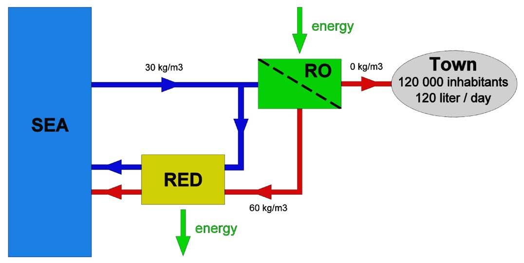
• RED as method for pre-desalination. Most seawater desalination plants use reverse osmosis (RO) for producing potable water. The process demands large quantities of energy. Moreover, they produce the same volumes of brine that are discharged in the sea and pose a threat to aquatic life. These plants are usually located in the neighbourhood of towns and these towns produce about the same quantity of impaired water as consumed drinking water. In principle, this sewage can be purified and made suitable for human consumption. However, this entails risks for public health due to technical imperfections of the treatment plants. In addition, some religions prohibit the use of wastewater for consumption.
Fortunately, that wastewater can still be used to generate energy together with the incoming salt water that goes to the RO filter (Figure 2). The major additional advantage is that the incoming seawater is already partly desalinated, so that the costs for operating the RO part will fall considerably. Another big advantage is that the RO brine is already diluted and no longer causes an osmotic stress on marine life. Saving energy on the RO
The Journal of Ocean Technology, Vol. 18, No. 1, 2023 29 Copyright Journal of Ocean Technology 2023


30 The Journal of Ocean Technology, Vol. 18, No. 1, 2023 Copyright Journal of Ocean Technology 2023
REDSTACK
Figure 2: Assisted reverse electrodialysis (ARED) method for energy saving of the reverse osmosis (RO) process.
Table 1: Theoretical potential of salinity gradient energy (SGE) in the world.
REDSTACK
Figure 3: Utilization of reverse osmosis (RO) concentrate together with seawater for energy harvesting.
part is actually even more important than the energy harvested with the RED part. Therefore, the RED part can be operated in the ARED (assisted RED) mode. By adding electrical energy, extra salt is transported from the seawater to the wastewater. Because it concerns a transport along the gradient, this requires relatively little energy.
• RED from RO concentrate with seawater. Seawater desalination produces a large amount of high salinity waste that is a threat for marine life. This brine can be used to feed a RED stack, together with seawater (Figure 3). Due to the pretreatment procedure, the brine is ready for use without further cleaning. The seawater is pre-treated together with the inlet stream for the RO unit. A further advantage is that the brine is already diluted before being discharged at sea.
World Potential
The main source of SGE is the combination of sea and river water and this makes it possible to estimate the global potential (Table 1). The average value of the potential energy content of river water can be used for an estimation of the global power. This is about 1.7∙MJ/m3 , supposing that a 1:1 volume ratio is used.

The total discharge of all rivers in the world is estimated to be 1.13∙106 m3/s. Therefore, theoretical global potential power is 1.9∙TW. More realistic estimates that take into account all kinds of physical limitations still amount to 1 TW. Figure 4 shows the places where SGE harvesting is a good option; the indicated values here relate to technical potential. In 2020, the world electricity production was 26,823,200 GWh, or an average power production of 3.1 TW. Therefore, SGE can supply one-third of the world’s electricity demand. The advantages of SGE are:
• Available 24 hours a day
• An inexhaustible source of energy
• No CO2 exhaust
• No thermal pollution
• No radioactive waste
• No daily fluctuations in production due to variations in wind speed or sunshine
REDstack BV
REDstack BV originated as a spin-off company from the water technology institute Wetsus in the Netherlands. In 2004, Wetsus started developing technology for generating energy from fresh and salt water. The choice had to be made to continue with RED or with pressure retarded osmosis (PRO), another SGE method. The RED technology has the advantages that
The Journal of Ocean Technology, Vol. 18, No. 1, 2023 31 Copyright Journal of Ocean Technology 2023
Figure 4: Salinity gradient energy (SGE) sites in the world.
REDSTACK


32 The Journal of Ocean Technology, Vol. 18, No. 1, 2023 Copyright Journal of Ocean Technology 2023
Figure 5: The pilot of REDstack on the Afsluitdijk (closure dam) in the Netherlands.
REDSTACK REDSTACK
Figure 6: Location of the REDstack pilot on the Afsluitdijk (closure dam) in the Netherlands.
this process directly generates electrical energy, that it is not necessary to work with high pressures, and that the contamination, especially in the fresh water, is easier to manage. It soon became clear that this approach is promising and this was the reason for a number of participants in Wetsus to establish REDstack. The company is owned by its founder and entrepreneur Pieter Hack.
REDstack wants to make a great contribution in the energy transition industry. REDstack wants to achieve this by adding Blue Energy as a technology as much as possible to the sustainable energy supply in the Netherlands and the world. This can be achieved by stepwise upscaling, starting from the current pilot, via a demonstration installation of 3 MW and then to largescale implementation. The potential in the Netherlands is 1,750 MW of full continuous sustainable power.
The pilot plant on the Afsluitdijk (closure dam) (Figures 5 and 6) was built after a period of long preparation. The Dutch King WillemAlexander conducted the grand opening in 2014. The pilot is located on a dam between Wadden Sea and IJssel Lake. Seawater is supplied via a pipe bridge over the motorway. The brackish mixture is transported also via the same pipe bridge but discharged into the small rescue harbour at the seaside to prevent mixing with the salt water inlet. REDstack developed the test stacks set up there together with several project partners. REDstack is not only responsible for the overall process technology but also for the development and manufacturing of the key components of the stacks (Figure 7).
REDstack BV focuses on two applications:
• RED – There is widespread interest in
the RED lab stacks from Spain, Canada, Colombia, Sweden, Denmark, and Turkey. This interest shows a broad and global focus on the development of the REDstack RED technology.

• Electrodialysis (ED) – The classic method of desalination was distillation. Later this technique was almost entirely adopted by reversed osmosis. ED appears to be a beneficial alternative to RO when it concerns the desalination of brackish waters, and it is the ideal technique for applications such as desalination of cooling water in power stations.
Spin-off
The development of the RED technology has resulted in a number of spin-offs.
• Optimized electrodialysis – In the RED-technology some sophisticated improvements are developed. They include the application of segmented electrodes and multistage designs. These concepts can also
The Journal of Ocean Technology, Vol. 18, No. 1, 2023 33 Copyright Journal of Ocean Technology 2023
Figure 7: A commercial reverse electrodialysis (RED) stack also deployable for electrodialysis (ED). REDSTACK

34 The Journal of Ocean Technology, Vol. 18, No. 1, 2023 Copyright Journal of Ocean Technology 2023
REDSTACK
Figure 8: Implementation of salinity gradient energy (SGE) in smart sustainable delta cities.
be applied to electrodialysis.
• Energy Storage – In times of a surplus of electricity, this energy can be used to separate salt water by means of electrodialysis into a quantity of desalinated water and a quantity of brine. In times of energy shortage, electrical energy can be generated with RED. A variant of this system uses acid and base, which gives a ten times higher storage capacity. The Dutch company Aqua Battery is developing and implementing this technology.
• Heat to power – Waste heat below 1000C is difficult to handle with conventional techniques for the generation of electrical energy. Within the framework of the “RED Heat-to-Power” project, a system has been developed for the utilization of this energy source. A RED stack is fed with a fresh and a saline stream. After leaving the stack, the concentrations are returned to their original values in a thermal regenerator. Two alternatives have been optimized. One is based on the distillation of water and the other on the transport of a volatile salt such as ammonium carbonate.
Future
The CO2 emission resulting from burning fossil fuels causes global warming, more
extreme weather conditions, and a rise in sea levels. Energy transition means that fossil fuels will be replaced by alternatives. Due to the growing world population and increasing prosperity, these new sources must yield even more than is produced with the current resources. The two pillars on which the energy transition will be based are the development of new forms of nuclear energy and the use of renewable energy sources.
Renewable resources are free from drawbacks associated with nuclear power, and are inexhaustible. They are based on wind, tide, geothermal energy, hydropower, biological residues, and salinity gradients. Energy based on sun and wind is very variable, in contrast to bio-energy, hydropower, and SGE. Hydropower is already being used on a large scale but will not expand in application because of very negative ecological and societal impacts; for SGE, this is at an experimental stage and the future is bright. An artist impression of the implementation of SGE in smart sustainable delta cities is shown in Figure 8.
Figure 9 shows a prediction of the levelized cost of energy (LCoE) for the period from today to the year 2050 and is based on the

The Journal of Ocean Technology, Vol. 18, No. 1, 2023 35 Copyright Journal of Ocean Technology 2023
REDSTACK
Figure 9: Levelized cost of energy (LCoE) trends in renewable energy sources.
renowned Dutch research organization TNO, and the consultants Witteveen & Bos, and CE Delft. Once a SGE plant capacity reaches 100 MW, the LCOE will be the equivalent of C$0.16 (€0.11) / kWh. This price is more attractive than the energy that will be released by most large-scale power storage systems as batteries, compressed gas storage systems, and the redox flow battery. The price per kWh of SGE will go down to less than $0.074 (€0.05) / kWh well before 2050, due to further upscaling and economies of scale.
The various forms of renewable energy are not competitive; rather they are complementary, with each form having its specific possibilities and limitations. As far as SGE is concerned, the strength is that it is available 24 hours a day. This type of energy has the potential to be a significant contributor to the global energy mix, as it is a renewable and abundant source of power.
One of the main challenges to the widespread adoption of salinity gradient energy is the high upfront capital costs associated with building and operating the necessary infrastructure. Despite the challenges, there is growing interest in salinity gradient energy as a renewable energy source. Several pilot projects have been implemented around the world, and research and development efforts are ongoing to improve the technology and bring down costs. It is expected that salinity gradient energy will play a significant role in the future energy mix, particularly in coastal areas where there is a natural abundance of seawater. u
Dr. Joost Veerman obtained his PhD in 2010 at the University of Groningen with a thesis titled Reverse Electrodialysis –design and optimization by modeling and experimentation. Immediately afterwards, he joined REDstack BV as research manager. His interests are (reverse) electrodialysis, ion exchange membranes, and renewable energy. He participated in the publication of 35 papers about these items.
Pieter Hack is a successful Dutch entrepreneur in sustainable technologies and is a process engineer by training. Having been involved with work in the field of electrodialysis, he was early to recognize and adapt the potential of this technology to produce Blue Energy by reversing the process. His entire career is focused on scaling up and implementing environmental and energy technology. Mr. Hack holds an MBA from INSEAD and a master’s degree in environmental technology/water treatment from Agricultural University of Applied Sciences Wageningen. Currently, he is a member of supervisory boards at the Dutch Marine Energy Centre, Wetsus Supervisory Board, European Centre of Excellence for Sustainable Water Technology, AquaBattery BV, Planet-e BV, and the Royal Dutch Association of Water Professionals.
Dr. Rik Siebers has been with REDstack since 2012 and has 30+ years of experience in water management. He is extremely well connected at the highest levels of Dutch politics and has strong lobbying power. Through various positions and board functions, he is often appointed to enable business partners and regional/local governments to work together. Dr. Siebers completed his master’s and PhD, both in research and education, at the Delft University; and he has participated in several executive programs at INSEAD, Nyenrode Business University, and the London Business School. Currently he is a member of the Confederation of Netherlands Industry and Employers, which functions to create an optimal business environment in the northern part of the Netherlands.


Michael van Oostrom has been with REDstack since 2021 and has 30+ years of experience in international business management. After graduating with a B.Sc. from Michiel de Ruyter Naval College, his career started at sea, first in the Merchant Navy and later at the Royal Netherlands Navy. Following a career path onshore in high-tech naval defence equipment, he later worked in electro-chemical and maritime sectors on international projects worldwide.

36 The Journal of Ocean Technology, Vol. 18, No. 1, 2023 Copyright Journal of Ocean Technology 2023


ISTOCKPHOTO.COM/ARVACSABA 38 The Journal of Ocean Technology, Vol. 18, No. 1, 2023 Copyright Journal of Ocean Technology 2023
Spermaceti Candle Wind of New Technology to the Holding a
 by Keith Alverson and Fong Ku
The Journal of Ocean Technology, Vol. 18, No. 1, 2023 39
Copyright Journal of Ocean Technology 2023
Over 200,000 whales were killed in the 19th century, by wind and sail powered whaling ships, in pursuit of an oceanic source of renewable energy. Spermaceti, a relatively clean burning liquid wax found in the sperm whale’s head, was particularly prized as lighting fuel. The term “candle power,” coined in 1860, was an official unit of illumination defined as the light produced by a pure spermaceti candle of weight 76 grams, burning at a rate of 7.8 grams/hour.
A right whale’s body provides about 4,200 gallons of refined whale oil. Multiplying by the estimated number of animals killed indicates that, over the course of the entire 19th century, about a billion gallons of whale oil were harvested, refined, and burned. By comparison, the U.S. in 2022 consumes nearly a billion gallons of petroleum – every single day. It would take roughly 10 to 100 million annual whale deaths to meet the energy demands of American households today. Currently, there are fewer than 350 North Atlantic right whales left in the world.
A gallon of whale oil in the 1850s cost about the equivalent of C$0.52 ($0.38 USD) per gallon, which, accounting for inflation, would be approximately $18 ($13 USD) in 2022 –substantially more than we pay at the pump. Even at such a high price, whaling as a source of energy was profitable, partly because it used wind and human energy to operate the ships. A modern whaling operation would clearly require more energy than it could capture.
It was this high cost of whale oil, or more accurately, the lower cost (and higher quality) of newly discovered alternatives, namely petroleum, which ended whaling’s dominance as a source of energy. New fossil fuel based technology made whaling uneconomical. What can we conclude?
As the story goes, technological advancements – the ready availability of cheaper alternatives – allowed us to quickly end our reliance on whaling, literally saving the whales. Unfortunately, the “technology saved the
whales” story is more nuanced, and mostly false. Fossil fueled, advanced ship technology gave the whaling industry the speed they needed to catch and kill any whale, anywhere. In the 20th century, powered by fossil fuels, whalers would slaughter a staggering 2.9 million whales, the largest cull of any animal, by biomass, in human history – so far. Pollution, noise, and habitat construction continue to impact whale populations. Traditional, subsistence whale hunting activities, which in some cases persist at sustainable levels, are threatened by high levels of toxins, including mercury. Petroleum did not save the whales.
What about the hope for new renewable technology to save the planet from our energy addiction? The main issue here is that our energy use is far higher than it has ever been – more than 10 times the amount we were consuming when we transitioned from whale oil to petroleum. This makes the problem of swapping out energy sources also more than ten times harder. Renewable technologies, including those showcased in this issue that extract energy from the ocean, are wonderful – but they are highly unlikely to be sufficient to “save the planet” unless we also reduce our enormous demand for energy. u
Dr. Keith Alverson is grateful to call Ordanakis, in the territory of the Sokokis Abenaki, home. He has been active in ocean research and international cooperation for over 20 years, including developing insights into the mechanisms of deep ocean convection; participating in the development of the Indian Ocean Tsunami Warning system; reporting on the adequacy of ocean climate essential variables to the UN Framework Convention on Climate Change; implementing actions to enhance resilience to sea level rise; and serving on the editorial board of the Journal of Ocean Technology

Fong Ku is grateful to call Mohkinstsis home, the traditional territory of the Niitsítapi, where there is plenty of sunshine and wind, and no whales. She studied and worked in international development prior to becoming a librarian. She currently works at the Alberta University of the Arts, one of four Canadian public universities dedicated to art, craft, and design.

40 The Journal of Ocean Technology, Vol. 18, No. 1, 2023 Copyright Journal of Ocean Technology 2023
ALUMNI MARINE INSTITUTE
and evaluation
• Resume/CV critique
• Mock interviews
• Job search skills – personal branding, networking, job search resources
• Resume referral services
• Job postings
Special events
news
rates on insurance services
Alumni
card
discounts
University library access
Stay connected and up to date on new alumni services, events, latest news and how you can become involved. www.mi.mun.ca/alumni/reconnectwithmi alumni@mi.mun.ca 1 800 563 5799, ext. 0367 linkedin.com/edu/ FisheriesandMarineInstituteofMemorialUniversity youtube.com/marineinstitutepr facebook.com/ MarineInstituteAlumni twitter.com/ MarineInstitute instagram.com/marine.institute
AND BENEFITS RECONNECT NOW!
• Access to career events •
• Reunions • Degree frames • Alumni and campus
• Group
•
credit
• Retail
•
CAREER SERVICES
SERVICES
OceanEnergy’s OEBuoy (OE35) is the world’s largest capacity floating wave energy device.

42 The Journal of Ocean Technology, Vol. 18, No. 1, 2023
OCEANENERGY Copyright Journal of Ocean Technology 2023
Creating a Step Change for the Wave Energy Industry
 by Tony Lewis and Lars Johanning
The Journal of Ocean Technology, Vol. 18, No. 1, 2023 43
Copyright Journal of Ocean Technology 2023
Wave energy is one of the most valuable renewable energy resources in the world, but the huge potential that it offers has yet to be realized. The pioneering Wave Energy Demonstration Utility Scale to Enable Arrays (WEDUSEA) project is setting out to prove the commercial viability of wave energy.
The Significant Potential of Wave Energy Waves have the highest energy density of renewable energy sources, compared to others like wind, solar, biomass, and geothermal. This means that harnessing wave energy can be an important contributor to the world’s energy mix resilience. The Intergovernmental Panel on Climate Change puts the potential annual global production, from wave energy, at 29,500 TWh. This is almost ten times Europe’s annual electricity consumption of 3,000 TWh.
Typical areas of high wave energy resource are on the western coastlines of landmasses adjacent to the world’s ocean basins. This includes the Atlantic Ocean in Europe and Africa, the Pacific Ocean along the North and South American coasts, as well as a large number of offshore islands distributed throughout the ocean.
The waves are generated by the wind, accumulating the energy and carrying it, with very little loss, across the ocean. This means that the waves are concentrating the wind energy from the whole ocean surface and transporting it to the downwind coast as swell. Consequently, there are many occurrences where wave energy is available at the coastline during times of low wind locally, thus making a combined system of wind turbines and wave energy converters less variable.
It is, therefore, no surprise that many countries around the world – including the U.S., Australia, China, Denmark, Italy, Korea, Portugal, Spain, and the United Kingdom –are currently developing wave energy. One of the largest and most ambitious projects is the WEDUSEA project (valued at the equivalent of C$28.9M (€19.6M)).
The WEDUSEA project
WEDUSEA is a pioneering collaboration between 14 partners spanning industry and academia from across Ireland, the U.K., Spain, France, and Germany. The partnership is co-ordinated by Irish company OceanEnergy and is co-funded by the European Union’s Horizon Europe Programme and Innovate UK, the U.K.’s innovation agency. The project kicked off in September 2022 and will run for four years.
The WEDUSEA project will demonstrate a grid connected 1 MW OE35 floating wave energy converter (WEC; Figure 1) at the European Marine Energy Centre’s (EMEC) Billia Croo test site in Orkney, Scotland.
The project will demonstrate this large-scale wave energy converter to increase experience in real sea conditions with a 24-month deployment period to confirm performance, availability, and reliability. The combined actions of the work plan are expected to reduce the levelized cost of energy for the technology by over 30%. The outcomes of this project will help to de-risk investments in wave energy and serve as a stepping-stone to large-scale commercialization of the technology.
The project has three key overall objectives.
• To demonstrate that wave technology is on a cost reduction trajectory, thus stimulating larger commercial array scale up and further industrialization, through de-risking larger scale investments. This will, therefore, help meet the 1 GW target set out in the 2030 DG-ENER Offshore Renewable Energy Strategy and the 2050 EU renewable energy targets
• To boost the development of the wave energy industry worldwide, by creating awareness of the potential of wave energy among policy-makers, industry, potential investors, and the public, thus directly impacting policy, public perception, and investor confidence in wave energy.
44 The Journal of Ocean Technology, Vol. 18, No. 1, 2023 Copyright Journal of Ocean Technology 2023
• To disseminate results and outcomes that enable the capitalization and exploitation of the results through new innovations, products, and services, as well as feeding both environmental databases and worldwide technical standards.
While a number of wave energy technologies have been tested up to Technology Readiness Levels 6/7, they have not completed extended demonstrations due to mechanical and operational issues.

The WEDUSEA project will draw on learnings from previous projects, such as Components for Ocean Renewable Energy Systems and the U.S. Navy Wave Energy Test Site Hawaii in order to enhance manufacturing methods, scalability, modularity, installation procedures, power performance, operations and maintenance, and supply chain, bringing the technology to Technology Readiness Level 7.
Gaining experience of operating an offshore wave energy converter over an
extended period of time (two years) will generate real availability and reliability data to better validate power performance modelling software being offered to developers. The operational experience during the deployment offshore will also yield valuable data on access limits of the device in various weather conditions and the parameters related to offshore operations and maintenance and insurance.
The WEDUSEA partnership
In addition to the project co-ordinator, OceanEnergy, the project partners are Innosea (France and U.K.); Advanced Simulation Technologies (Spain); The Fraunhofer Institute for Energy Economics and Energy System Technology IEE (Germany); University College Cork (Ireland); Gavin & Doherty Geosolutions (Ireland); Exceedence Ltd. (Ireland); Wood (Ireland); Hydro Group Ltd. (U.K.); European Marine Energy Centre (U.K.); Longitude Consulting Engineers Limited (U.K.); University of Exeter (U.K.); and Green Marine (U.K.) Ltd. (Figure 2).
The Journal of Ocean Technology, Vol. 18, No. 1, 2023 45 Copyright Journal of Ocean Technology 2023
Figure 1: The WEDUSEA project will demonstrate a grid connected 1 MW OE35 floating wave energy converter at the European Marine Energy Centre’s test site in Orkney, Scotland.
OCEANENERGY
Each partner brings its own leading-edge technical skills and research expertise to the WEDUSEA project.

The partnership involved in the delivery of this project comprises some of the most experienced companies, research institutions, and universities in the wave energy space. The deployment will be for two years at the world renowned European Marine Energy Centre in Orkney, Scotland, commencing in summer 2024. The wave energy converter will be moored in 60 m water depth, located about 5 km from the shore, and connected – via a submarine cable – to the onshore electrical grid at Orkney.
This will be the largest grid connected WEC of its type worldwide when in operation.
The Project Phases
The project has three distinct phases:
1. The first phase is the initial design of a device suited to the EMEC’s test site ocean conditions.
2. The second will be the fabrication of the device and integration of the machinery, followed by the demonstration at the site, lasting two years.
3. The final phase will be commercialization and dissemination that sees the capitalization and exploitation of the results. The partner companies will actively exploit the results through new innovations, products, and services. The results will also be disseminated to feed both environmental databases and International Electrotechnical Commission (IEC) electrotechnical standards.
The WEDUSEA Technology – the OE35 OceanEnergy has developed the OEBuoy (OE35), the world’s largest capacity floating wave energy device. The technology has already been extensively tested and is now at a stage where it is one of the most commercially viable technologies for wave energy.
The OEBuoy has been progressively developed following the Ocean Energy Systems testing
46 The Journal of Ocean Technology, Vol. 18, No. 1, 2023 Copyright Journal of Ocean Technology 2023
Figure 2: WEDUSEA is a collaboration between 14 partners spanning industry and academia from across Ireland, the U.K., Spain, France, and Germany.
WEDUSEA
protocols and conforming to the Evaluation and Guidance Framework requirements. The device has been tested at small scale in laboratory wave tanks (Figure 3) and then a one-third scale device, rated at 40 kW, was tested at the Irish Scale Test Site in Galway Bay for over three years, co-funded by the European Commission. This step-wise development through the Technology Readiness Levels has reduced the risks for future deployments.
The present demonstration device is 35 m long with a rated capacity of 500 kW. It was constructed using steel at the Vigor Industries shipyard in Portland, Oregon. This OE35 device will be tested at the U.S. Navy Test Site in Hawaii during 2023.
How the WEDUSEA Wave Energy Technology Works
There are many concepts for wave energy converters, but the one being developed by OceanEnergy is the oscillating water column (OWC). The OWC system consists of a large enclosure semi-submerged with an underwater opening to the sea and a large trapped-air volume above the waterline. As the waves oscillate, the wave pressures at the submerged opening cause the water to oscillate which forces air pressure inside the device, which is used to drive a built-in turbine to generate electricity. Furthermore, the OE35 can generate electricity not only when waves advance, but also when they recede, thanks to a component known as a Wells turbine. When the water recedes, it creates a vacuum and air rushes in to fill it, keeping the turbine spinning in the same direction, and the cycle repeats. The only moving part is the turbine rotor, which is above the waves.
This type of turbine is called self-rectifying and a number of designs exist. The one being used in the WEDUSEA project is a Wells Aerofoil Turbine, which is highly efficient during the reversing airflows. The diameter of the air turbine outlet is significantly smaller than the surface of the enclosed water column and this results in a gearbox effect
by speeding up the airflows through the turbine to be more compatible with electrical generator rotational speeds. As a result, no mechanical gearbox is required.
The OceanEnergy wave energy convertor (OEBuoy) has the OWC as a floating system supported by a large, sealed buoyancy chamber. This is a highly reliable and robust construction. The OWC has an L-shaped configuration to house the oscillating water in a tunnel length compatible with the expected wave conditions at the deployment site and this shape reduces the necessary draft of the device.
A number of existing wave energy devices have encountered barriers to commercialization. Prominent among these are:
• The difficulty of scaling up devices to generate large amounts of power and, therefore, to drive down the cost of the electricity they produce.
• Being robust enough to withstand the huge forces that waves can exert, together with the corrosive effect of saltwater on moving parts.
The OceanEnergy OE35 wave energy converter (Figure 4) overcomes these issues:
• It can be built at scale. The current version is more than five storeys high and weighs over 800 tonnes.
• There is only one moving subsystem, which is the air turbine runner, located above the waterline, with all of the required electrical and ancillary equipment housed within the watertight buoyancy chambers. Having the moving components sit well above the waves makes them much less prone to damage and corrosion.
• The construction of the OEBuoy uses steel and conventional shipbuilding technology making it ideally suited for mass production.
• The dynamic response of the device in large waves results in reduced mooring forces thus increasing the inherent survivability.
The Journal of Ocean Technology, Vol. 18, No. 1, 2023 47 Copyright Journal of Ocean Technology 2023

48 The Journal of Ocean Technology, Vol. 18, No. 1, 2023
OCEANENERGY Copyright Journal of Ocean Technology 2023
Figure 3: The OE35 has been tested at small scale in laboratory wave tanks.

The Journal of Ocean Technology, Vol. 18, No. 1, 2023 49 Copyright Journal of Ocean Technology 2023


50 The Journal of Ocean Technology, Vol. 18, No. 1, 2023 Copyright Journal of Ocean Technology 2023
OCEANENERGY
Figure 4: The OE35 has only one moving sub-system – the air turbine runner – located above the waterline. All required electrical and ancillary equipment is housed within watertight buoyancy chambers.
The WEDUSEA project is the natural progression of the OEBuoy development on the path towards commercialization. This project is an exciting development and will provide scale up to a 1 MW device to be deployed at a more exposed site typical of future wave farm sites.
For the WEDUSEA project, the OE35 will be adapted to work in the Atlantic Ocean conditions at the EMEC test site in Orkney.
The European Marine Energy Centre EMEC is the world’s first and leading test facility for wave and tidal energy converters. Established in Orkney in 2003, EMEC is now the world’s leading accredited test laboratory and inspection body for demonstrating wave and tidal energy converters, subsystems, and components in real sea conditions.
To date, more marine energy converters have been deployed in Orkney, Scotland, than at any other single site in the world, with 22 wave and tidal energy clients (from 11 countries) having tested 35 marine energy devices.
The OE35 device will be demonstrated at the Billia Croo test site over two winter periods, so that it is tested in the most challenging Atlantic sea conditions.
EMEC will provide metocean, bathymetry, and geophysical data to feed into the design criteria for the wave energy converter device and facilitate planning of offshore operations. EMEC will also lead on environmental monitoring and impacts.
The EMEC site deployment will enable collection of valuable data on performance and environmental impact. This will include a series of field campaigns spanning underwater and airborne acoustics, biophysical assessment of wave dynamics, fish aggregation and seabird analysis, assessing the connection between local species, and technology operation. This data will build on existing environmental studies to provide regulators with improved understanding
and reduced uncertainty around environmental impacts of wave energy.
EMEC operates to relevant test laboratory standards (ISO17025) enabling the Centre to provide independently verified performance assessments. It is also accredited to ISO/IEC 17020 offering technology verification on marine energy converters and sub-systems.
By providing world class testing and data collection and analysis, EMEC will help enable WEDUSEA to achieve its goal of proving the commercial viability of wave energy.
The Key Challenges
There are several challenges to be overcome. These include:
• Technology innovation. The OE35 design will incorporate a number of innovations related to the power conversion system, the mooring system and the operations and maintenance strategy. By using innovative control on the operations of the power take-off system, WEDUSEA aims to increase turbine efficiency of the primary power take-off system and increase the pneumatic power capture of the wave energy converter. This will be optimized during sea testing. We aim to increase turbine efficiency of the primary power take-off system from 70% to 75% with improved air turbine design and the inclusion of an airflow control system and associated control strategies.
• Project management. As a project with 14 partners based in multiple countries (and the largest U.K./Europe project since Brexit), there are practical challenges related to internal project management and joint working.
• Device scale. This will be the largest wave energy device of its kind ever constructed, which will set new challenges in terms of engineering design, installation, and maintenance.
The Journal of Ocean Technology, Vol. 18, No. 1, 2023 51 Copyright Journal of Ocean Technology 2023
• Operations. The long-term operational experience will be valuable albeit challenging as no other wave energy converter has previously demonstrated seaworthiness for a two-year period. The reliability, survivability, ease of maintenance, and power performance indicators derived during this project will contribute to increased confidence in future deployments of the technology and critically to their “bankability” by investors and third party funders.
• Performance measurement. Thorough data monitoring and measurement of device performance over the two-year deployment will be needed. This will yield a huge quantity of data needing expert analysis using the range of capabilities of the partners.
• Environmental. The OE35 is expected to be deployed in a harsh marine environment; therefore, there is an engineering challenge associated with designing the device to withstand higher wave loads. Additionally, it is important to understand any impacts that the device may have on marine and bird life, and the steps that could be taken to mitigate this.
• Cost. By reducing the levelized cost of energy by over 30%, this demonstration project will show that the technology is on a cost reduction trajectory. However, the challenge of achieving this target reduction will depend on a number of variables regarding device construction, installation, and operation.
We are confident that our partnership will rise to the full range of challenges. Each key challenge that we face has a specific work package assigned to it, with a nominated Lead Partner who takes responsibility for delivering that package to schedule. As the project develops, we will give regular updates on our progress on the WEDUSEA website .
We believe that the successful demonstration of the OE35 in the WEDUSEA project will pave the way for future deployment of multiple devices in an array to form a wave energy farm. This will be the stepping-stone to full commercial rollout for wave energy projects that will help to achieve renewable energy targets worldwide.
We look forward to sharing our findings and results with the ocean energy renewables community. u
Prof. Tony Lewis, PhD, M.Sc., B.Tech., is chief technical officer at OceanEnergy – an Irish technology development company working in the field of wave energy. OceanEnergy is co-ordinating the WEDUSEA project. He is co-PI emeritus in Science Foundation Ireland funded Centre for Marine and Renewable Energy in University College Cork, Ireland. Prof. Lewis has been a member of Ocean Energy Europe since its foundation (as European Ocean Energy Association) and a board member since 2010. Formerly, he was inaugural professor of energy engineering with overall responsibility for the academic programs in B.E. (Hons.) energy engineering and M.Eng.Sc. sustainable energy in the School of Engineering at University College, Cork, Ireland –and emeritus Beaufort Professor since 2018.

Prof. Lars Johanning, PhD, Dipl.Ing., FHEA, is chair of ocean technology at the University of Exeter. He has a PhD from Imperial College in science, technology, and medicine. He is a leading international researcher in the field of ocean energy and technology with a focus on hydrodynamics and mooring systems. Prof. Johanning has led the development of the Falmouth Bay marine energy test site, which has seen the successful deployment of multiple wave energy devices. He provided the technical lead in the development of the EU Ocean Energy Strategic Roadmap. Prof. Johanning has longstanding relationships with Chinese organizations focusing on research and development of U.K.-China partnerships in offshore renewable energy. He was recently awarded a U.K.-China-BRI Countries Partnership Fund, designed to boost multilateral education partnerships to pioneer new developments addressing global challenges.

52 The Journal of Ocean Technology, Vol. 18, No. 1, 2023 Copyright Journal of Ocean Technology 2023
Bridging the Gap to Commercialization of Wave Energy Technology using Pre-commercial Procurement
 by Peter Dennis
The Journal of Ocean Technology, Vol. 18, No. 1, 2023 53 ISTOCKPHOTO.COM/ERLANTZ PÉREZ RODRÍGUEZ
Copyright Journal of Ocean Technology 2023
Introduction
Against a backdrop of energy security concerns, net-zero goals, and economic instability, governments worldwide are making bold policy decisions relating to green technologies, including renewable energy sources. In Europe, the EU’s ambitious climate targets and policy initiatives have encouraged individual countries to set their own ambitious national targets in relation to renewables. It is perhaps natural that the Atlantic-facing regions and those bordering the North Sea, with an exposure to a significant wave energy resource, view the wave energy sector as being of strategic importance in meeting these targets.
The ambitions and priorities for the wave energy sector in these countries are expressed in high-level terms: providing support for industrial and academic ocean energy research and development and investment (R&D&I); supporting testing infrastructure that nascent ocean energy technology would be reasonably expected to require; encouraging diversification in existing supply chains; and developing financial policies to support deployments.
The priorities emerging from recent technology roadmaps and strategic research agendas, which focus on technological aspects, are perhaps best summarized as “learning by doing at a meaningful scale.” This priority is compatible with the highlevel national and regional priorities.
The European Technology and Innovation Platform for Ocean Energy’s 2019 summary of the state-of-the-art for ocean energy technologies highlighted the need to “pull” the most promising wave energy technologies forward to a Technology Readiness Level (TRL) 6-8 and thus bridge the gap between publicly funded R&D&I and commercial investment. To achieve this requires the deployment of prototype “whole-systems” of a substantial scale in representative and operational wave climates.
The European Commission’s Strategic Energy Technology Plan has set ambitious targets for ocean energy technologies targeting the electricity utility market, challenging the wave energy sector to reduce its levelized cost of energy (LCOE) to at least the equivalent of C$0.30 (20 c€)/kWh by 2025, $0.22 (15 c€)/kWh by 2030, and $0.15 (10 c€)/kWh by 2035.
While producing power at the utility scale is a focus for many wave developers, and has a bigger impact on high-level targets, the emerging Blue Economy offers an alternative route to market. Technological innovation is fuelling high-growth maritime industries, including marine aquaculture, ocean observation, marine robotics, biofuels, and seawater mineral extraction. Wave energy technology can play a unique role in these sectors, providing power at sea in off-grid and offshore locations, untethered from land-based power grids.
What is Wave Energy?
Wave energy technologies capture the movement of surface waves and swell, and use it to create energy – usually electricity. The amount of energy created depends on the speed, height, and frequency of the wave, as well as the water density.
Wave energy can provide utility-scale power production and works very well in tandem with other renewables such as wind power. It is also a clean, infinitely available alternative to polluting and expensive diesel for remote islands and offshore industries.
Today, scaled and full-size wave energy prototypes are being tested at sea. The most advanced device developers are planning and building the first multi-device wave energy farms around Europe, most notably in the U.K., Portugal, Spain, and Italy. Once built, these pilot farms will serve as a basis for commercializing wave energy technology and building a new European industry.
What is EuropeWave?
EuropeWave is an R&D&I program to advance
54 The Journal of Ocean Technology, Vol. 18, No. 1, 2023 Copyright Journal of Ocean Technology 2023
the most promising designs for wave energy converter systems to the point where they can be commercially exploited through other national/regional programs and/or private sector investment. These designs will have been validated through testing in multiple program phases, progressing from physical modelling at small scale in a test tank through to deployment of prototypes of a substantial scale and size at the open-water test facilities of the Biscay Marine Energy Platform (BiMEP) in the Basque Country and the European Marine Energy Centre (EMEC) in Scotland.
The EuropeWave program is a C$28.9 (€19.6) million cross-border joint pre-commercial procurement of R&D&I services. Wave Energy Scotland (WES) and the Basque Energy Agency have joined forces to form a “buyers group” that shares a common ambition and pooling national funding to undertake a single joint procurement process. The program’s budget is co-funded through the European Union’s Horizon 2020 research and innovation program under grant agreement no. 883751.
The program is run in collaboration with Ocean Energy Europe, which provides expertise and guidance in the dissemination of project outputs and a direct link with the wider ocean energy sector.
The motivation for the buyers group is to support renewable energy policy objectives and to deliver economic benefits in the supply chains and economically fragile coastal/island communities. The buyers group is committed to procuring the best solutions from anywhere in Europe with a proviso that the physical demonstrations are carried out in Scotland and the Basque Country.
These regions are well placed to reap the potential environmental, economic, and social benefits of a maturing wave energy sector. Both regions boast a number of strategic advantages, namely:
• Significant exploitable wave resource
• Indigenous R&D&I capability
• Indigenous wave energy technology developers
• Supply-chain opportunities
The main technical challenges to be addressed by the wave energy technology designs being developed through EuropeWave may be expressed in terms of:
• Performance – addressed by obtaining quantitative evidence of appropriate power capture and conversion capability, and an associated increase in confidence in yield predictions from numerical model simulations.
• Survivability – addressed by demonstrating effective strategies for survival in survival events.
• Availability – addressed by demonstrating levels of availability through reliable prototype operation.
• Affordability – addressed by increasing confidence in the estimation of the technology costs (capital and operational) and determining a route to cost reduction to achieve a competitive LCOE.
The International Energy Agency’s (IEA) International Evaluation and Guidance Framework for Ocean Energy Technology presents a framework for technology evaluation and guidance of engineering activity throughout the technology development process. The Framework is built upon an international consensus on the evaluation of ocean energy technology and is intended to support decision-making associated with technology evaluation and funding allocation, ensuring decision-makers have consistent information available to them.
The EuropeWave pre-commercial procurement (PCP) is using the IEA Framework as the basis for its technology development program. The IEA Framework breaks the technology development process into six stages, from concept creation to commercialization (Figure 1). The three
The Journal of Ocean Technology, Vol. 18, No. 1, 2023 55 Copyright Journal of Ocean Technology 2023
phases of the EuropeWave PCP cover Stage 2 and Stage 3 of the IEA Framework.
At each stage, a collection of technical activities is proposed, focused on the Framework’s nine key evaluation areas (Figure 2).
What is Pre-Commercial Procurement?
Pre-commercial procurement (PCP) is a form of public sector innovation procurement. A procurer identifies a need for which no commercially-proven, or near-to-the-market, solution exists and new R&D&I is required to create a solution. PCP is a specific approach to procure the necessary R&D&I services. PCP allows the procurer to compare the pros and cons of alternative competing solutions.
This industrial development process creates a “funnel” via a multi-phase funding program.
At the start, developers can apply for support via an open call. In the subsequent phase, the most promising projects are selected through a competitive process to continue into the next phase, concentrating the remaining funding on the best-performing technologies (Figure 3).
Technologies that progress to the final phase will be demonstrated in Basque and Scottish open waters at the end of the program.
This model, first implemented in Scotland by WES, is an alternative approach to conventional R&D&I funding. It optimizes public spending on wave energy innovation by providing up to 100% funding in priority areas that need improved solutions. In EuropeWave, the focus is on demonstration of appropriately scaled prototypes in an operational environment.
The process creates market pull for the most promising technologies (through an open competition) and its “phase-gate” converging process then concentrates funding on the most successful projects. Projects that successfully complete all phases of the PCP program will have demonstrated that their technology has the performance and reliability required to proceed to system qualification and early commercialization.
The Attraction of PCP for EuropeWave PCP is a staged procurement process that

56 The Journal of Ocean Technology, Vol. 18, No. 1, 2023 Copyright Journal of Ocean Technology 2023
IEA
Figure 1: The International Energy Agency (IEA) Framework’s six-stage technology development process, and how it relates to EuropeWave.
can be mapped onto the staged development process
technology
Framework).
The PCP model was an attractive option for EuropeWave for several reasons. As an approach to purchasing the R&D&I activities necessary to progress technology development, PCP facilitates the participation of small companies and there is no obligation for technology developers to match fund,
meaning that a broad range of participants and associated technologies are brought forward for assessment. The R&D&I services are purchased at a market rate. The multi-contract phased approach maintains a competitive environment during the program and avoids being locked-in with a single provider.

For technology developers, PCP brings the benefit of a level of continuity in funding, and promising technologies can expect

The Journal of Ocean Technology, Vol. 18, No. 1, 2023 57 Copyright Journal of Ocean Technology 2023
IEA
Figure 2: The International Energy Agency (IEA) Framework’s nine evaluation areas.
EUROPEAN COMMISSION
Figure 3: Competitive development phases of the pre-commercial procurement process.
for wave energy
(i.e., the aforementioned IEA
to progress. The aforementioned fact that no match funding is required is also very attractive for developers.
On the downside, there is undoubtedly an administrative burden for the procurers running the PCP. It must be an intelligent client, with a strong understanding of its requirements and a robust entry and phase gate assessment process. Independent experts can be used during application assessments to augment internal expertise and to help reinforce a principle of openness.
Program Overview
The EuropeWave PCP program consists of three phases, as shown in Figure 4.

Phase 1
A total of 35 compliant applications were received for the EuropeWave program and after the assessment process seven contractors were accepted into Phase 1 of the PCP. This first phase allowed the selected R&D&I providers to progress their concept engineering designs and undertake such physical and numerical modelling as required to establish the technology’s characteristics (e.g., performance, survivability, etc.). Smallscale tank testing campaigns under defined environmental conditions were completed to allow the buyers group to understand the performance potential of the wave energy converter (WEC) systems.
The core objectives for Phase 1 of the EuropeWave PCP were to:
• Optimize the concept engineering design for the EuropeWave requirements.
• Benchmark performance.
• Estimate the Phase 3 power performance capability.
• Evidence that the WEC system is on track to provide an attractive commercial offering.
The tasks and activities proposed for Phase 1 had to be appropriate to address the objectives and demonstrate relevant mitigations for critical system challenges. All Phase 1 projects were expected to complete a number of mandatory development tasks, consisting of:
• Conceptual design development of the complete system that will be tested in an open water environment during Phase 3.
• Physical testing of a small-scale model in a set of mandatory test conditions relevant to the Phase 3 test sites and defined by the buyers group.
• Independent review of tank testing activities, commenting on compliance with the technical specifications published by the IEC.
• Preliminary design review of the conceptual design for the Phase 3 prototype, highlighting the development progress made during Phase 1.
Phase 2
Five providers were selected to progress to Phase 2. They are currently completing this phase by continuing design development work
58 The Journal of Ocean Technology, Vol. 18, No. 1, 2023 Copyright Journal of Ocean Technology 2023
Figure 4: EuropeWave program timeline.
EUROPEWAVE
on each of the five technologies in Phase 2 is provided below.
The Arrecife Trimaran (Figure 5) is a floating platform with a modular and scalable turbine system, where multiple turbines, each of which is connected to an electrical generator, are used to capture wave energy and produce electricity. The turbine design is intended to mimic the behaviour of coral reefs, by breaking the waves and extracting the energy. The future aim for this WEC technology is to develop 0.3 MW units, multiples of which can be installed in an array for mass electrical energy production connected to the electrical grid.

The AMOG SeaSaw WEC (Figure 6) technology involves a dual hinged, twin hull, combined surge and pitch device with two rolling mass power take-offs (PTOs) on curved tracks. The hinge-linked hulls, with their independent PTOs and the resulting induced “SeaSaw” motion, are designed to enhance power production and widen the range of suitable operational conditions. The fundamental design aims and principles of the WEC technology are to avoid contact between moving parts and seawater, use commercially available subsystems proven in other industries, ensure ease of installation through use of conventional catenary mooring lines and anchors, and ease of operations by allowing a
PTO while the WEC remains on its mooring.
The ACHIEVE project intends to deliver a design of the CETO WEC technology (Figure 7), which is a submerged buoy tethered to the seabed. The project integrates new innovations, collaborates with experienced partners, and focuses on optimizing performance and cost while leveraging learnings from prior design and deployments. This should provide step change improvements to the CETO technology while retaining compelling features, such as fully submerged operation, which minimizes visual impact and offers inherent protection from breaking waves and storms. The new CETO design developed in EuropeWave is estimated to capture nearly twice as much energy as previously deployed CETO systems, due to an enhanced mooring, a new fully electric rotary PTO design, and an advanced control strategy that optimizes capture from every wave and can modify the position in the water column for both enhanced energy capture and survivability.
IDOM’s wave energy harvesting technology is a point absorber based on the oscillating water column working principle called MARMOK (Figure 8). The basic device concept can be described as a spar element holding a cylindrical water column inside. During operation, due to wave excitation, a relative
The Journal of Ocean Technology, Vol. 18, No. 1, 2023 59 Copyright Journal of Ocean Technology 2023
Figure 5: Arrecife Trimaran. ARRECIFE


60 The Journal of Ocean Technology, Vol. 18, No. 1, 2023 Copyright Journal of Ocean Technology 2023
Figure 6: AMOG SeaSaw.
AMOG
Figure 7: CETO WEC.
CETO WAVE ENERGY IRELAND
movement between inner water column and buoy is produced. This makes the water column act like a piston that compresses and expands the air chamber in the upper section of the buoy, generating a reciprocating airflow that is then converted into electric power by passing through an air turbine.
Mocean Energy is developing the Blue Horizon 250 (Figure 9), which is the latest embodiment of its recognizable WEC architecture and builds on the successes and lessons learned at smaller scale with the BlueX architecture in the WES program. The WEC features a hinged raft with forward and aft wave channels that are geometrically optimized using Mocean’s inhouse expertise, and a direct-drive electric Vernier hybrid machine PTO. Within EuropeWave, Mocean proposes to build a first-of-a-kind version of a 250 kW WEC product, bringing in additional funding as required to support manufacture and operations. This ambitious target serves to maximize the benefits of the program, and crucially to accelerate the technology towards commercialization. The commercial applications for a 250 kW Blue Horizon device include offshore oil and gas, islands and remote communities, and early grid projects, where nearer to longer term value propositions have been identified.
The core objectives for the five contractors in Phase 2 are to complete a FEED for a prototype device to be constructed and tested in Phase 3. The phase will close with each technology undergoing a critical design review of its complete proposed system, to review readiness for progression and to enable contractors to begin to work with fabrication providers to obtain detailed quotations for the build in Phase 3. In addition, Phase 2 work will progress numerical simulations, financial modelling, and will develop operational plans for the Phase 3 deployment. The FEED design, along with installation and operation and maintenance plans, will be reviewed by an independent third party, to give the buyers group confidence on the quality and veracity of the technology proposals. The anticipated outcome of Phase 2 correlates to Stage 2 of the IEA Framework.
Phase 3
In Phase 3 of the EuropeWave PCP, prototype representations of three designs will be deployed at the open-water test facilities of either BiMEP in the Basque Country or at EMEC in Scotland for a demonstration and operational testing program of at least 12 months in duration. The initial phase of testing is anticipated to include a work-up program to commission the system and subsystems, prior

The Journal of Ocean Technology, Vol. 18, No. 1, 2023 61 Copyright Journal of Ocean Technology 2023
Figure 8: IDOM MARMOK.
CONSULTING ENGINEERING
to demonstrating sustained periods of operation to deliver electricity and survival in extreme environmental conditions.
The main objectives of the Phase 3 testing program are:
• To validate the design’s power capture and conversion capability through operational data recorded during sustained periods of operation in the energy producing sea states.
• To demonstrate the effectiveness of survival strategies.
• To demonstrate approaches that will enable commercial levels of availability in the future.
Successful completion of the EuropeWave PCP program corresponds to the substantial completion of Stage 3 of the IEA Framework; the equivalent of achieving TRL 6.
Conclusion
The EuropeWave program brings together experience from Ocean Energy Europe and the partners in the buyers group to
implement a PCP-based procurement for the development of wave energy technology. By using PCP, the procurers were able to draw in many potential technologies to be investigated, and the phase-gate process enables the selection of the best performers to be progressed towards commercialization.

Since this route to commercialization is a key aim of EuropeWave, contractors within the program are required to develop and maintain plans that set out the measures that will be undertaken to continue the development of the design of the WEC system towards a commercial application after the conclusion of the EuropeWave PCP. As a minimum, these plans identify a technology development roadmap to successfully deliver the WEC system to market, and demonstrate how the financial capability and capacity for doing so will be established during the PCP.
The success to date of using the PCP model for wave energy development, through the EuropeWave and Wave Energy Scotland programs, has led to initial discussions regarding the possibility of a follow-on
62 The Journal of Ocean Technology, Vol. 18, No. 1, 2023 Copyright Journal of Ocean Technology 2023
Figure 9: Chris Retzler with a model of the Mocean Blue Horizon 250.
MOCEAN ENERGY
program. This would provide an opportunity for a wider selection of national and regional partners to take part, and open up access to a greater variety of devices and test locations.
Wave energy is a key part of addressing the twin challenges of climate change and energy security – so it is crucial to get machines in the water and clean power into the European grid without delay. Models such as the PCP open up new ways of thinking about the procurement of energy technologies and, fundamentally, can provide a springboard to get more renewable sources onto the grid. u
Dr. Peter Dennis has been a project manager with Wave Energy Scotland (WES) since 2005. He has managed WES’s oversight of different projects within the program, including the development of the AWS Ocean Energy WaveSwing. Prior to this, Dr. Dennis has experience of renewable energy and project management in the public, private, and academic sectors. He has a degree and PhD in civil and structural engineering.

The Journal of Ocean Technology, Vol. 18, No. 1, 2023 63 Copyright Journal of Ocean Technology 2023
G See equipment live with 180+ hours of free training & demonstrations


G Navigate the year ahead and have your questions answered at the free conference


Copyright Journal of Ocean Technology 2023 oceanbusiness.com
G Meet 360+ world leading manufacturers and service providers
G Discover the latest marine autonomous systems, survey tools and biological and chemical sensors
REGISTER NOW FOR FREE Be at the forefront of ground-breaking innovation TRANSFORM YOUR BUSINESS 3 DAYS HUNDREDS OF SOLUTIONS In partnership with: Hosted by: National Oceanography Centre THE HANDS-ON OCEAN TECHNOLOGY EXHIBITION AND TRAINING FORUM OB23_A4 Ad half.indd 1 28/09/2022 11:40
Stored Energy in the Sea

Combining 3D Printed Pumped Hydro Energy Storage Systems with Floating Offshore Wind in California
by Christian Dick, Jonas Sprengelmeyer, and Gabriel Falzone
The Journal of Ocean Technology, Vol. 18, No. 1, 2023 65
FRAUNHOFER IEE Copyright Journal of Ocean Technology 2023
Introduction
The energy production of wind turbines increases when they are located near the shore or even offshore since the wind speeds are higher and the wind blows more freely compared to locations in the countryside.
The installation site has an impact on the design of the turbine, which generally leads to higher rotor diameter but lower hub heights for offshore or nearshore wind turbines, but also affects several other design parameters due to the harsher environment. Neglecting these differences, the increased wind speed and quality at offshore locations have the potential to nearly double the energy yield of a wind turbine installed at an offshore site compared to an installation of the same turbine in the countryside. Consequently, there are widespread efforts to increase the number of offshore wind plants worldwide. While most offshore wind plants are installed in shallow water up to 50 m water depth, there are many coastlines where the water depth increases to higher depths near the shoreline. In these regions, floating offshore wind turbines are an option to utilize the wind energy potential.
One of these regions is California in the United States of America. California has set itself ambitious climate targets and is planning to reduce CO2 emissions. For this reason, Senate Bill 350 increases California’s renewable electricity procurement goal from 33% by 2020 to 50% by 2030 and to 100% by 2045 as mandated by Senate Bill 100. To achieve this goal, California must advance the development of diverse renewable energy generation and storage technologies. Among other technologies, floating offshore wind (FOW) will play a key role in this strategy. For this reason, there are currently two advertised wind energy areas (WEA) for FOW off the California coast. One of the regions stands out for its potential to install an innovative offshore pumped hydro energy storage system, which is being developed by the Fraunhofer Institute for Energy Economics and Energy System Technology IEE. In this essay, we explain the
basic working principle of this storage system and highlight the advantages of a combination with an offshore wind farm in one of the wind energy areas in California. Additionally, we introduce RCAM Technologies’ approach to 3D concrete printing of renewable energy infrastructure and discuss the potential applications in manufacturing FOW anchors and the StEnSea system.
StEnSea System
The innovative offshore pumped hydro energy storage system, also known as StEnSea system (Stored Energy in the Sea system), has been proven in a field test in a first research project. The StEnSea system consists of two main components. The first one is a hollow concrete sphere representing the storage tank and the other is the cylindrical technical unit holding the pump turbine, a controllable valve, and the components of the Supervisory Control and Data Acquisition system. The technical unit is removable and can be recovered separately, which facilitates maintenance and repairs.
The working principle and operating modes of the StEnSea system are similar to conventional pumped hydro energy storage systems (PHES), which use the pressure difference resulting from a height difference between an upper and a lower storage reservoir or lake. In StEnSea, the water body surrounding the sphere represents the upper storage reservoir, while the sphere interior represents the lower reservoir.
An empty sphere corresponds to a fully charged storage unit, while a filled sphere corresponds to a fully discharged one. During discharge, opening the controllable valve enables water to flow through the technical unit into the sphere. The inflowing water drives a turbine and a generator that feeds electricity into the grid. Using energy from the grid to pump the water out of the sphere against the surrounding water pressure recharges the storage system. Figure 1 illustrates this working principle.
The dimensions of the full-scale system are given in Table 1. They are the result of a
66 The Journal of Ocean Technology, Vol. 18, No. 1, 2023 Copyright Journal of Ocean Technology 2023
feasibility study carried out by HOCHTIEF Solutions AG before the start of the first research project to determine the size and weight of the sphere, which is still manageable with the existing offshore logistics, resulting in an outer diameter of approximately 35 m. Following the selection of the diameter, two main criteria in the design of the sphere have to be ensured. On one hand, the sphere must
withstand the ambient water pressure; on the other hand, the weight of the system must be larger than its buoyancy to ensure that the sphere remains on the seabed even when it is empty. Both conditions are addressed by varying the wall thickness, since the weight and, thus, the compressive strength of the sphere increases with the wall thickness. Up to a certain water depth, the buoyancy condition


The Journal of Ocean Technology, Vol. 18, No. 1, 2023 67 Copyright Journal of Ocean Technology 2023
Figure 1: Working principle of the Stored Energy in the Sea (StEnSea) system.
Table 1: Technical data of the Stored Energy in the Sea (StEnSea) system.
FRAUNHOFER IEE
is decisive for the wall thickness, as it depends solely on the amount of water displaced and is, therefore, independent of the water depth itself. Once the depth exceeds this threshold, the wall thickness must be increased to ensure that the sphere withstands the water pressure. This water depth threshold is approximately 750 m, which is, therefore, chosen as the rated installation depth. However, it is possible to install the sphere in lower or higher water depths. In deeper water, the capital costs would increase due to a higher amount of concrete for the required wall thickness and with it the costs for installation and transport. An installation in a lower water depth would be possible without a constructive change of the concrete sphere, but due to the lower pressure difference between the interior of the sphere and the surrounding water, the pump turbine would have to be adjusted and the energy storage capacity would decrease.
A key advantage of the StEnSea system over conventional PHES is that it offers large areas for new installation sites in deepsea waters with very limited conflicts of use, while the potential of conventional PHES is closely connected to geographical conditions and often raises environmental issues due to land use conflicts and the impact on the water regime. A site evaluation with a geographical
information system was carried out to identify potential installation sites worldwide. The following values and thresholds were used to derive the worldwide potential of the StEnSea system:
• Water depth: 600 m-800 m
• Slope: ≤ 1°
• Distance to the electrical grid: ≤ 100 km
• Distance to maintenance bases: ≤ 100 km
• Distance to installation bases: ≤ 500 km
• Unsuitable geomorphology such as trenches, spreading ridges, rift valleys, canyons, seamounts, escarpments, fans
The results in Table 2 show a worldwide potential, which exceeds the required storage need by far. Of course, there are more and less suitable locations within the resulting areas, but the techno-economic assessment must be performed individually for each site.
During the first research project in 2016, a 1:10 scaled prototype was built and successfully tested in Lake Constance. Figure 2 shows a photo of the installation. Additional simulations and analysis regarding the fullscale system moved the StEnSea system from Technology Readiness Level (TRL) 2 to 5. The investigations showed that the technical implementation in the targeted scale is possible.

68 The Journal of Ocean Technology, Vol. 18, No. 1, 2023 Copyright Journal of Ocean Technology 2023
Table 2: Worldwide Stored Energy in the Sea (StEnSea) potential.
A follow-up research project, which is currently being negotiated with the funding agencies, aims to demonstrate the possibility to install the system in the intended water depth. It will help to gain new insights into the offshore installation and operation. Through continuous operation, it will be possible to analyze and assess long-term effects on the concrete sphere and pump turbine. The planned work would move the technology to TRL 6, preparing the realization of commercial full-scale systems. If the promising results of the first research project can be continued, the StEnSea system could become an important component of the future energy storage portfolio.

Floating Offshore Wind Areas in California
The wind resources off the coast of California have the potential to make a significant contribution to California’s electricity generation and to diversify the state’s energy mix. There are currently two advertised WEA for FOW in California: Humboldt WEA and Morro Bay WEA. In December 2022, an auction was held for the two areas, auctioning offshore areas with a potential of 4.5 GW and an area of 1,500 km². The potentially installed
FOW turbines at these sites could supply more than 1.5 million households with electricity.
In California, high offshore wind speeds at short distances from the coast meet great water depths between 500-1,300 m. This makes the region not only attractive for the use of FOW but also for the StEnSea system. The entire area in the Morro Bay WEA is at least 900 m deep, which would require an altered technical unit. However, an analysis by Fraunhofer IEE shows that there are great matches between the potential StEnSea system locations and the Humboldt WEA. Figure 3 shows the results of the location analysis.
As shown in Figure 3, the call area is divided into lease blocks and aliquots, with each aliquot being a square of 1,200 m by 1,200 m, equal to 1.44 km², and each block containing 16 aliquots in four rows of four, equal to 23.04 km².
The potential StEnSea system locations in the Humboldt WEA sum up to an area of approximately 120 km², which is about 20% of the total WEA. Assuming the installation of 400 spheres in an area of one km², the
The Journal of Ocean Technology, Vol. 18, No. 1, 2023 69 Copyright Journal of Ocean Technology 2023
Figure 2: Installation of 1:10 scaled Stored Energy in the Sea (StEnSea) model in Lake Constance.
FRAUNHOFER IEE
total capacity would be about 1.5 TWh, which is equal to the annual consumption of approximately 150,000 households in the U.S. This exceeds the storage demand in this region by far.
Within the techno-economic analysis, the standard size of a StEnSea system park considers 80 spheres, which sum up to a power of 400 MW and a capacity of 2.5 GWh. This StEnSea system park would require an area of approximately 0.2 km² and would, therefore, easily fit in the WEA without limiting the wind energy potential. This is particularly true due to the required distances in between the wind turbines. Figure 4 shows four 15 MW wind turbines with their required distances drawn to scale. In the direction of wave, wind, and current the turbine spacing should be at least 7 rotor diameters and at least 4 rotor diameters in the perpendicular direction to reduce wake effects. Each wind turbine has three anchors that are installed in a specific distance to the wind turbine. This distance varies with the chosen mooring system, but even for the catenary mooring system with the longest distances, it is easily possible to fit a 400 MW StEnSea system park in between the wind turbines.
The combined installation enables a couple of operation modes. The first one is to combine both technologies, but to operate them separately. This would offer the chance to share the cost for the offshore infrastructure as well as the grid connection including the subsea cables. Additionally, the wind farm could be operated in combination with the StEnSea system park. Floating offshore wind farms, like other renewable technologies, are also weather dependent and there is a chance that there is no demand for electricity during particularly strong winds. The generated wind energy would then have to be curtailed or stored. Adding a StEnSea system park with additional storage capacity would allow for a significantly smoother and more reliable energy feed-in as changes in wind speed could be compensated.
Other advantages of the StEnSea system locations in the advertised WEA are an easier granting of permit for the installation and the joint use of the infrastructure for the grid integration, operation, and maintenance between the wind farm and the storage system. Furthermore, mooring systems in which the spheres could theoretically be used as anchors themselves are not applicable, since

70 The Journal of Ocean Technology, Vol. 18, No. 1, 2023 Copyright Journal of Ocean Technology 2023
Figure 3: Stored Energy in the Sea (StEnSea) locations in Humboldt wind energy area (WEA).
FRAUNHOFER IEE
the distance between two anchors is much larger than the distance between two spheres within the original layout of the storage park. The design of the sphere itself would have to change due to the installation in a variety of depths and, hence, additional load.

Considering these aspects led to the conclusion that it is preferable to use separate anchoring and storage systems. RCAM Technologies is developing innovative anchor systems for FOW plants that are made using 3D concrete printing technology. 3D concrete printing uses an automated robotic system to create complex concrete structures without the labour needs of conventional concrete forming. Compared to conventional casting, 3D concrete printing can reduce the cost of manufacturing complex designs, reduce labour cost, increase safety, and enable lean and sustainable manufacturing in a port. RCAM’s designs include concrete suction anchors and torpedo anchors, which are projected to reduce costs, reduce carbon emissions, and create more local jobs than typical steel anchors. Figure 5 shows representations of RCAM’s torpedo and suction anchors and the 3D concrete printing process.
As the construction of the StEnSea sphere is one of the largest costs of the system, there is potential to apply new construction methodologies such as 3D concrete printing to reduce costs. RCAM completed a proofof-concept print with its partner Vertico in the Netherlands, which demonstrated that it is possible to print a spherical structure using present day 3D concrete printers. Figure 6 shows photographs of this completed print. RCAM is continuing to scale up and demonstrate the 3D concrete printing technology.
Conclusion
The wind resources off the coast of California have the potential to make a significant contribution to California’s electricity generation and to diversify the state’s energy mix. Additionally, the Humboldt WEA stands out for its potential to install an innovative offshore pumped hydro energy storage system, which is being developed by the Fraunhofer Institute for Energy Economics and Energy System Technology IEE. A combined use could have several benefits such as:
• Cost reduction through shared use of
The Journal of Ocean Technology, Vol. 18, No. 1, 2023 71 Copyright Journal of Ocean Technology 2023
Figure 4: Wind turbine area with different mooring systems. WWC = wave, winds, currents. 4D = 4 rotor diameters. 7D = 7 rotor diameters.
FRAUNHOFER IEE


72 The Journal of Ocean Technology, Vol. 18, No. 1, 2023 Copyright Journal of Ocean Technology 2023
Figure 5: Artist’s renderings of 3D concrete printed torpedo and suction anchor technologies for floating offshore wind.
RCAM TECHNOLOGIES RCAM TECHNOLOGIES
Figure 6: Photographs of 3D Stored Energy in the Sea (StEnSea) proof-of-concept print by RCAM Technologies and Vertico.
infrastructure for the grid integration, operation, and maintenance.
• Easier permission progress within borders of WEA without a loss of production capacity.
• Increased quality of the energy production through balancing services with the storage system.
• Higher capacity utilization or optimization of the export cable.
Furthermore, 3D concrete printing has the potential to:
• Reduce cost of manufacturing complex designs
• Reduce labour cost
• Increase safety
• Enable lean and sustainable manufacturing in a port
This essay shows that a successful development of the StEnSea system combined with modern 3D printing construction will benefit the key technology of floating offshore wind and its expansion to reduce CO2 emissions and can have a significant impact on the sustainable energy supply system of the future. u
Dipl.-Ing. Christian Dick is an electrical engineer working at Fraunhofer IEE in Kassel since 2013. As a member of the Energy Storage department, his research topics cover the design and development of energy storage systems as well as the optimization of the control management, their grid integration, and technoeconomic analysis. He has been involved in the development of the StEnSea system since the beginning and was the technical project manager for the first research project.


Jonas Sprengelmeyer is a student at Clausthal University of Technology and is currently writing his master thesis at Fraunhofer IEE in Kassel on a technoeconomic feasibility study of StEnSea system. He has a background in industrial engineering with a focus on energy and raw materials. His expertise and areas of interest are grid integration of renewable energy and underground hydrogen storage.
Dr. Gabriel Falzone is the director of operations at RCAM Technologies. He has a PhD in materials engineering from University of California, Los Angeles, specializing in sustainable and low carbon concrete, with over 25 published papers. Dr. Falzone has experience in scaling up concrete technology pilots as the former VP, technology at CO2Concrete (now CarbonBuilt) – a winner of the $7.5 M NRG COSIA Carbon XPRIZE in 2020.

The Journal of Ocean Technology, Vol. 18, No. 1, 2023 73 Copyright Journal of Ocean Technology 2023
Making Better Blades for

74 The Journal of Ocean Technology, Vol. 18, No. 1, 2023
MAGALLANES RENOVABLES Copyright Journal of Ocean Technology 2023
Tidal Energy Generation

The Journal of Ocean Technology, Vol. 18, No. 1, 2023 75
Copyright Journal of Ocean Technology 2023
Introduction
Tidal energy is an essential part of Europe’s energy future. It is a clean, predictable energy source, and the potential tidal resource is huge. The European Union (EU) has set an ambitious goal to reach 100 gigawatts of installed capacity for wave and tidal energy by 2050.
Tidal currents are caused by the gravitational forces of the sun and the moon, and are particularly concentrated in narrow bodies of water, such as around islands or inlets. With an estimated global resource of 8001,200 terawatt-hours, tidal stream energy can contribute significantly to the decarbonization of our energy systems.
Tidal currents are not influenced by weather conditions, and it is possible to predict tidal energy production hundreds of years in advance. This long-term predictability makes tidal energy one of the most reliable sources of renewable energy available. It has a crucial role to play in a 100% renewables-powered Europe, as it is instrumental in guaranteeing an electricity baseload and balancing the grid.
The design of tidal turbine blades is crucial to the performance and efficiency of the device, and has a major impact on the upscaling of tidal turbines (Figure 1). A strong, welldesigned set of blades can increase annual
energy production and reduce operating costs and project downtime. Blade edges can erode rapidly, causing leaks, accelerating fatigue, and increasing the risk of failure. Improving the seaworthiness of blades will reduce the likelihood of this type of failure. There is also a need for further technology investigation and demonstration of improved reliability and efficiency of tidal turbine blades and rotor, including pitch and yaw control.
The European Strategic Energy Technology Plan (SET Plan) has established cost targets for tidal energy equivalent to C$0.22 (15 c€)/ kWh by 2025 and $0.15 (10c€)/kWh by 2030. Technological advances in areas such as blade design are an integral part of bringing down the levelized cost of energy (LCOE) in line with these targets.
Magallanes Renovables
Founded in 2009 by Alejandro Marques, Magallanes Renovables is a Spanish tidal energy developer, focused on the commercialization of floating tidal energy systems. The company aims to open and lead a new worldwide industry based on the exploitation of tidal energy – an unexploited and uniquely predictable renewable energy.
In 2017, Magallanes built its first full-scale tidal energy platform, the ATIR, equipped with

76 The Journal of Ocean Technology, Vol. 18, No. 1, 2023 Copyright Journal of Ocean Technology 2023
MAGALLANES RENOVABLES
Figure 1: Blade maintenance by diver.


The Journal of Ocean Technology, Vol. 18, No. 1, 2023 77 Copyright Journal of Ocean Technology 2023
Figure 2: (top) Launching of Magallanes’ full-scale prototype, the ATIR. (bottom) The ATIR in a dry dock for maintenance.
MAGALLANES RENOVABLES
MAGALLANES RENOVABLES
two tidal turbines (Figure 2). The ATIR is 45 metres long and 15 metres deep, with a total power production capacity of 2 megawatts (MW). The launch was followed by several months of electrical construction and towing tests, after which it was ready for action. Two years later, the ATIR was connected to the Scottish energy grid, successfully generating energy from tidal currents.
The NEMMO Project
The EU-funded NEMMO (Next Evolution in Materials and Models for Ocean Energy) project aims to create a larger and more durable composite blade for floating tidal turbines, enabling devices to reach capacities of over 2 MW. The innovative blade prototypes produced by the project will be used on Magallanes’ tidal turbines, mounted on its ATIR device.
This will boost the competitiveness of tidal energy by reducing its LCOE and increasing the yield of tidal turbines.
These dual goals will be achieved by optimizing the tidal turbine blade design and performance. To do so, the project team has designed a geometry to improve the fluid dynamic performance of the blade. To increase the useful lifespan of tidal blades, it has also made changes to reduce cavitation, improved resistance to fatigue, and reduced the cleaning needs of the blade by using innovative antifouling surfaces. Finally, the project will optimize the blade’s structural design to reduce mass production costs, and will also reduce the need for mechanical pitch changes to make this system cheaper to run, and to facilitate its installation in the marine environment.
Computer Modelling and Experimental Testing
The project work started with extensive computer modelling (Figure 3A), carried out by NEMMO project partner Technion (Israel Institute of Technology). The work studied potential cavitation effects on scaled-down versions of the blades and were used to predict the performance coefficient of the turbines.
This study encourages accurate and affordable simulations of multi-rotor devices in the future.
Tailor-made testing procedures were developed to carry out a sizeable experimental test program in a cavitation tunnel at the SSPA facilities in Sweden, with the aim of validating the computer simulation models carried out by Technion (Figure 3B). These testing procedures for integrated harsh marine stresses enable the replication and modelling of composite blade lifespan, cavitation wear rates, bio-fouling growth, aging in a harsh marine environment, and hydrodynamic performance.
Regarding the performance of the turbine blade, an investigation of the influence of cavitation and translation due to the yaw of the turbine was performed at four different yaw angles between 0° and 19.5° and four pitch angles in different tip speed ratios. As the initial results showed no influence of cavitation, the pressure for the first tests was at atmospheric pressure. The remaining tests were completed at overpressure, which was the actual hydrostatic full condition for the turbine.
Novel Materials and Nanotechnology
Developing novel materials and coatings for tidal turbine blades is one of the main objectives of the NEMMO project to increase their aging, fouling, impact, and cavitation resistance (Figure 4). To enhance blade material performance, three parallel approaches were carried out, namely: improving the fatigue and impact resistance of the new nano-enhanced composite materials, controlling biofouling by means of blade surface micro-texturing, and developing novel non-leaching anti-fouling coatings with permanent cavitation resistance.
The latter is achieved through the design and synthesis of polymers bearing different functionalities within its chemical backbone and the incorporation of functionalized nanoparticles into such polymer formulations. Functionalized silica nanoparticles and carbon nanocomplexes were also added to the coatings.
78 The Journal of Ocean Technology, Vol. 18, No. 1, 2023 Copyright Journal of Ocean Technology 2023
Furthermore, several formulations of the reference resin have been tested. Composite plates of glass fibre resin have been successfully manufactured for each formulation. Mechanical properties seem to be similar whatever the formulation, but new formulations are still under development. Characterization of the failure (adhesive or cohesive) and ongoing humid aging to assess moisture effect onto formulated materials is currently underway at the Spanish technological institute ITAINNOVA.

Reducing Biofouling with Biomimicry Biofouling, the development of nuisance or unwanted biofilms on surfaces, is a major problem due to accumulation of biomass causing reduced efficiency, contamination, corrosion, and failure of engineered components. Fouling in the marine environment has been an issue that has reduced the lifespan of structures, increased the fuel

consumption of vessels, increased maintenance frequency, and spread invasive species for as long as humankind has been placing objects in the water. Biofilm formation is most readily recognized in marine and freshwater environments where a cursory glance at a surface, such as a ship’s hull immersed for even a short period (weeks), reveals a multitude of organisms attached to and populating surfaces.


The study of surface topographical features has become increasing popular in recent years, with several investigations reporting sophisticated natural topographies found on many organisms that are known to have antifouling properties. The replication of artificial surfaces inspired by nature –known as biomimicry – has produced many promising results.
Studies have shown a mixture of attachment, depending on the size and shape of the
The Journal of Ocean Technology, Vol. 18, No. 1, 2023 79 Copyright Journal of Ocean Technology 2023
Figure 3: (left) High fidelity fluid dynamic simulation animation. (right) Cavitation tunnel tests with 1:38 model.
SSPA INPRE ITAINNOVA
Figure 4: (left) Static test bench installed at ITAINNOVA. (right) Additive infusion process to fibreglass laminates.
organism and the specific microtexture used as a fouling-resistant mechanism (Figure 5). However, the explanation behind this attachment is still not well known. Numerous theoretical models have been proposed through the years in order to understand this attachment behaviour. One of these models is the attachment point theory.
In this model, the fouling organism experiences increased attachment where there are multiple attachment points and reduced attachment when the number of attachment points are decreased. This can often be related to micro-texture, in the sense that highly intricate topographies (i.e., whereby the micro-texture is smaller than that of the organism) will not be favourable for attachment. On the other hand, where the micro-texture is larger than the organism, settlement does occur.

An application of the micro-texture discussed here is for the control of antifouling on advanced tidal turbine blades. The successful incorporation of antifouling technology onto tidal turbine blades could unlock significant potential for the use of ocean energy, reducing cleaning costs and allowing the extraction of energy from the blade system. Surface texturing has been shown here to be effective under static immersion. Field tests under dynamic conditions are ongoing as part of the project to assess the impact of hydrodynamic stresses under real sea conditions.
The testing of micro-textured surfaces showed that the cluster of biofouling organisms covered all candidate textures. The best results were obtained with sharp edge, raised, rectangular bars, leading to a 13% decrease in the cell coverage, a 42% decrease in the colony size, and a notable reduction in the nearest neighbour distance. If feasible, more significant reductions could also be achieved with narrower gaps between neighbouring structures.
Fatigue and Full-scale Ocean Testing
One full-size blade will undergo resonance fatigue testing at the Blaest Blade Test Centre (Figure 6). Innovations are also being made in the fatigue test processes of the blade bed, which in the tidal energy sector has not yet reached the same level of development as in the wind sector.
At the end of the NEMMO project, the blades will also be installed on the ATIR, Magallanes Renovables’ full-scale platform. Full-scale testing is necessary to test the operation and control, to enable verification of all aspects of the device performance. This kind of testing is usually carried out at the European Marine Energy Centre’s offshore site. The data collated from the real scale demonstrator will be used for the validation of the simulation results and the optimized blades performance evaluation during a complete tidal cycle.
Due to the floating nature of Magallanes’ platform and its dimensions, it is foreseen that waves’ effect will be secondary. Besides, the variable pitch system can control blade orientation to reduce the potential impact of waves in the blades. The effects of waves, tides, and other unexpected fluctuating loads will be considered in the project during the load definition.
The difference with respect to the smaller diameters tested so far not only affects the maximum achievable power, but also the energy production at low tidal speeds, which significantly affects the annual energy
80 The Journal of Ocean Technology, Vol. 18, No. 1, 2023 Copyright Journal of Ocean Technology 2023
Figure 5: Biofouling growth mechanism.
DUBLIN CITY UNIVERSITY
production, an evident improvement in the income derived from the sale of energy. The counterpart is that the bending moments transmitted to the hub by the blades increase with their length. This important milestone will serve to measure these static and fatigue loads to validate the fluid dynamic simulations and drive the structural design of the new generation of tidal energy generators.

This project has received funding from the European Union’s Horizon 2020 research and Innovation programme under grant agreement 815278. u
Javier Grande graduated with a M.Sc. in industrial engineering in 2014 from the University of Vigo, where he specialized in electronics and automation. Since then, he has worked at Magallanes Renovables where he has performed various functions, initially working on the tests of the 1:10 scale prototype. In 2019, he led the ATIR (Magallanes Renovables tidal energy converter) energy generation test campaign. In 2021, he was involved in the design of new innovative blades for a tidal turbine for the NEMMO project. At the same time, he has actively been working on the performance assessment of new locations of tidal currents potentially usable by the Magallanes Renovables tidal energy converter ATIR. His current role at Magallanes is instrumentation and control software manager.
Marta Garcia, a mining engineer with over 10 years of experience in renewable energy, oversees the naval-mechanical department at Magallanes Renovables. She is responsible for the development and growth of the company since its very early stages.

Pablo Carpintero has a B.Sc. in industrial electronics and automation engineering and a M.Sc. in mechatronics from the University of Vigo; and has three years’ of experience in renewable energy. At Magallanes Renovables, he is in charge of digital twin modelling and data analysis of Magallanes prototype and has previous experience in control design and automation for machinery of automotive and pharmaceutical sectors.
Adrián Delgado is a researcher with the Dublin City University (DCU) Water Institute. He completed a B.Sc. in biology at Universidad Autónoma de Madrid (UAM) in 2017; a M.Sc. in water quality and microbiology in 2018 from Interdisciplinary Centre of Marine and Environmental Research and UAM; and is currently finishing his PhD in analytical chemistry at DCU. Mr. Delgado investigates how biofouling adheres to the surfaces of different materials, coatings, and bio-inspired micro-textured materials using techniques based on image segmentation in combination with machine learning in order to create growth models to understand their behaviour and thus select the best compounds for use in the marine tidal energy industry.


The Journal of Ocean Technology, Vol. 18, No. 1, 2023 81 Copyright Journal of Ocean Technology 2023
Figure 6: Blade breakage test.
MAGALLANES RENOVABLES
Dr. Chloe Richards is a researcher with the Dublin City University (DCU) Water Institute. She completed a B.Sc. in analytical science at DCU in 2017 and finished her PhD in analytical chemistry in 2022. Dr. Richards’ PhD investigated the hypothesis that bio-inspired micro-textured materials can disrupt marine biofouling. She is currently working as a postdoctoral researcher on the I-SECURE project that aims to evaluate the sources and occurrence of contaminants of emerging concern in the marine coastal and transitional waters.

Fiona Regan is founder and director of the Dublin City University (DCU) Water Institute and is a full professor in chemistry at the School of Chemical Sciences in DCU. Prof. Regan’s research focuses on analytical chemistry in the field of environmental monitoring, and she has special interest in priority and emerging chemicals as well as the establishment of decision support tools for environmental monitoring using novel technologies and data management tools. Her work includes the areas of separations and sensors (including microfluidics), materials for sensing, and antifouling applications on aquatic deployed systems.

82 The Journal of Ocean Technology, Vol. 18, No. 1, 2023 Copyright Journal of Ocean Technology 2023
Integration of Wave Energy Devices with Chambered Breakwater K. Aiswaria, Balaji Ramakrishnan, and Debarshi
 Sarkar
Harvesting Wave Energy
Researchers Aiswaria, Ramakrishnan, and Sarkar assess the hydrodynamic efficiencies of wave energy converter devices.
Who should read this paper?
Researchers and individuals interested in learning more about the development and performance of wave energy converters will find this paper useful. In addition, it may be informative to those who are interested in marine renewables.
Why is it important?
Wave energy is a highly promising renewable resource that has the potential to produce a substantial amount of clean energy. A viable way to harvest wave energy economically is to incorporate coastal structures with a wave energy converter. There is currently limited information on cylindrical buoys and cylindrical buoys with moonpool-type wave energy converters integrated into a chambered breakwater.
In this study, the hydrodynamic efficiency of a cylindrical heaving floating point absorber wave energy converter is examined when integrated with a breakwater. The power absorption performances of two types of models – a cylinder and a cylinder with a moonpool – are investigated. The average power generation performance of the models is found to increase after integration with the chambered breakwater. The study proves that such an integrated system serves as a multipurpose structure to harvest wave energy along with coastal protection.
About the authors
K. Aiswaria is a PhD scholar in the Ocean Engineering Division, Department of Civil Engineering, at the Indian Institute of Technology Bombay, India. Her research focuses on the hydrodynamics of floating body wave energy converters. Her research interests are wave-structure interaction, hydrodynamics of wave energy converters, and coastal protection structures.

Dr. Balaji Ramakrishnan is a professor in the Ocean Engineering Division, Department of Civil Engineering, Indian Institute of Technology Bombay, India. His research expertise broadly covers coastal and ocean engineering with a specific interest in wave-structure interactions, marine renewables, and nearshore dynamics.

Debarshi Sarkar is a final year bachelor of engineering student in the Department of Mechanical Engineering at Jadavpur University, India. He is interested in research on ocean engineering – particularly, in exploring sustainable solutions to the energy crisis, and renewable energy extraction from ocean waves and tides using wave energy converters.

Copyright Journal of Ocean Technology 2023
K. Aiswaria
Dr. Balaji Ramakrishnan
84 The Journal of Ocean Technology, Vol. 18, No. 1, 2023
Debarshi Sarkar
INTEGRATION OF WAVE ENERGY DEVICES WITH CHAMBERED BREAKWATER
K. Aiswaria1, Balaji Ramakrishnan2, and Debarshi Sarkar3
1Department of Civil Engineering, Indian Institute of Technology Bombay, Mumbai, India
2Department of Civil Engineering, Indian Institute of Technology Bombay, Mumbai, India; rbalaji@iitb.ac.in
3Department of Mechanical Engineering, Jadavpur University, Kolkata, West Bengal, India
ABSTRACT
Integration of wave energy devices with coastal protection structures could be a potentially feasible option to produce energy economically. This paper aims to assess the hydrodynamic efficiencies of wave energy converter (WEC) devices under (i) stand-alone floating conditions and (ii) when integrated with a chambered breakwater. Two different WEC model shapes, considered in the study, are a cylinder and a cylinder with a moonpool for constant mass and diameter conditions. The influence of the moonpool is observed on the hydrodynamic coefficients and heave response characteristics. The results reveal that upon integration with the chambered breakwater, the power performances of the WEC model increased by a maximum factor of 3.65 as compared to stand-alone models. The findings of the study encourage such integration of wave energy converters in coastal structures as an alternate option to enhance wave energy.
KEYWORDS
Wave energy converter; Cylinder with moonpool; Chambered breakwater; Power performance; Capture width ratio
The Journal of Ocean Technology, Vol. 18, No. 1, 2023 85 Copyright Journal of Ocean Technology 2023
1. INTRODUCTION
The need to develop alternative renewable energy technologies has led to a wide variety of wave energy converters (WECs). Among WEC concepts, floating point absorbers are reportedly the most favourable and relevant to practical applications [Guo et al., 2022]. Floating point absorbers (FPAs) are floating WECs that absorb maximum energy when the incident wave frequencies match the body’s natural frequency [Payne et al., 2008]. FPA absorbs wave energy from waves larger than its structural dimensions [Faizal et al., 2014] and is said to be economical regarding fabrication, installation, and maintenance. Generally, FPAs consist of a floating component attached to a power take-off (PTO) device that transforms the absorbed energy into usable electricity [Guo and Ringwood, 2021]. The responses of FPAs depend significantly on their geometric shape and generally operate in heave mode, unaffected by the wave direction [Al Shami et al., 2019]. Hence, axisymmetric FPAs, such as cylinders, spheres, and cones, have been the focus of many studies in the past.
Eriksson et al. [2005] investigated the performance of a cylindrical point absorber with a linear generator numerically and established that, for a harmonic wave, the power capture ratio increases when the system is in resonance with the wave. According to Chen et al. [2016], an optimum damping coefficient exists for the maximum power conversion of a horizontal floating cylinder. A spectral analysis of the motion of a vertical floating cylinder demonstrated a peak motion corresponding to a predominant frequency that appears to be the natural frequency of the wave
and the body [Song et al., 2016]. Compared to fully submerged vertical cylinder buoys, floating buoys absorb more power at longer wavelengths and have broader bandwidth [Sergiienko et al., 2017].
The nonlinear behaviour of WEC devices in power production mode can be relevant depending on the sea state, the geometry, and the motion of the device. Since the cylinder has a constant cross sectional area, geometric nonlinearities may be insignificant [Penalba et al., 2017]. Guo et al. [2017] simulated a linear dynamics model and a non-linear model of a cylindrical single-body FPA and verified it against experimental study results. It was proven that the linear model is accurate enough for modelling scaled WECs. For heaving cylindrical WECs, the kinetic energy is mainly concentrated in the seaward and leeward sides of the device, and causes the maximum pressure and flow velocity on the bottom of the model at these positions [Yu et al., 2021]. Cylindrical WECs in heave and pitch motion have the potential to achieve higher power absorption rates at larger scales and those in surge and heave have higher power absorption at smaller scales [Garcia-Teruel et al., 2022].
It is suggested that cylindrical models with a moonpool may be favourable for wave energy applications due to less surge motion and smaller line forces [Gravrakmo, 2014]. BOLT Lifesaver is a point absorber device developed by Fred. Olsen team of engineers and manufactured by U.K. engineering company Supacat Ltd. The Lifesaver, named after the shape of the hull – a flat hollow cylinder – is a lightweight system that provides a locally generated power supply, with a communication
86 The Journal of Ocean Technology, Vol. 18, No. 1, 2023 Copyright Journal of Ocean Technology 2023
line to the shore and favours remote operation [BOLT Lifesaver System, 2016]. Zheng et al. [2020] investigated wave energy extraction using a floating hollow cylinder capped by a roof, combining the advantages of cylindrical point absorbers and torus-shaped buoys. Based on the tested wave conditions, the power absorption is reportedly at maximum when the aperture is either completely opened or closed. Intermediate values of the aperture are suggested to be used to minimize the heave motion, ensuring the survivability of the WECs under extreme sea conditions.
It is reported that the wave power extracted in the nearshore environment is on par with that of offshore wave energy [Folley and Whittaker, 2009]. Zanuttigh et al. [2010] examined the feasibility of using WECs for coastal protection through laboratory tests and suggested that the devices can be advantageously integrated with coastal protection schemes. A majority of the cost involved in WEC development is associated with the physical structure and its installation. Hence, combining WECs with coastal structures can yield significant cost reduction [Azzellino et al., 2013], even in places of low wave intensity. Buccino et al. [2015] explored the potential of a composite seawall for wave energy conversion and found that the system proves to be a multipurpose structure for wave energy utilization and coastal defence. The recent increase in sea level rise and the growing intensity of extreme events due to climate change require new replacement schemes. The combination of wave energy converters and harbour breakwaters may be a smart alternative and requires potential research [Vicinanza et
al., 2019]. Cascajo et al. [2019] evaluated the possibility of constructing an integrated breakwater and a WEC structure able to provide energy to the commercial port of Valencia and concluded that the port is an ideal location for integration of the WEC. Hybrid integration is an effective approach to harness energy efficiently; it also improves hydraulic performance of the breakwater with no evident negative impacts on the overall structural stability [Koutrouveli et al., 2021].
Krishnendu and Balaji [2020] investigated the hydrodynamic efficiency of a spherical WEC integrated with a chambered breakwater system. The breakwater consisted of a porous wall on the seaward side and a solid wall on the leeward side. As the waves entering the chamber undergo quasi-resonance conditions and become amplified, the power performance of the WEC model increases as compared to the results of modelling tests. The integrated system proves broad application in coastal infrastructures with no compromise in the reflection characteristics. Krishnendu and Balaji [2021] further studied the performance of a heaving plate model integrated with a chambered breakwater and successfully demonstrated its dual purpose. In this paper, the energy absorption efficiencies of a cylindrical WEC (CYL) model and a cylinder with a moonpool (CM) model in heave, under stand-alone conditions, using regular wave elevation time series, and integrated with a chambered breakwater system (CBW), using the experimental wave elevation inside the CBW in the absence of the model, obtained from Krishnendu and Balaji [2020], are investigated. The influence of mass and external diameter on the model performance
The Journal of Ocean Technology, Vol. 18, No. 1, 2023 87 Copyright Journal of Ocean Technology 2023
are analyzed and presented. This paper is structured as follows: Section 2 details the numerical investigation of the models for the adopted test conditions. Section 3 presents the results of the study and compares and demonstrates the performance of the models. Finally, the conclusions are shown in section 4.


2. NUMERICAL INVESTIGATIONS

Numerical investigations of the hydrodynamic efficiencies of CYL and CM models for constant mass and diameter conditions are studied with the wave elevation time histories, measured inside the chamber, from the laboratory experiments of Krishnendu and Balaji [2020] for the model integrated with CBW cases and with regular wave time series for stand-alone models. In the wave tank experiments, the wave elevations were measured in the absence of the models, at two positions of the chamber: (i) at a distance of 0.2 m from the permeable wall (P1) and (ii) at a distance of 0.2 m from the solid wall (P2). To study the influence of integration with CBW, these wave elevation time series are used in the time domain analyses. The schematic representation of the wave flume with the stand-alone model and with the model in the chambered breakwater at P1 are shown in Figure 1 and Figure 2, respectively.
2.1 Model Details and Test Conditions
The effect of geometry on power absorption performances of the CYL and CM models are investigated under constant mass and water plane area, in the first stage (constant mass case). In this case, the draft is also nearly equal. Further, the models are tested under constant diameter conditions (constant diameter case). Here, the water plane area, mass, and draft vary for both models as the diameter is the same. Model details at constant diameter conditions are shown in Figure 3. Table 1 and Table 2 give descriptions of the different model configurations considered in this study.
88 The Journal of Ocean Technology, Vol. 18, No. 1, 2023 Copyright Journal of Ocean Technology 2023
Figure 2: Schematic diagram of the wave energy converter (WEC) model at P1 inside the chambered breakwater (CBW) in the wave flume.
Figure 1: Schematic diagram of the wave energy converter (WEC) model in the wave flume.
Figure 3: Typical cylinder (CYL) and cylinder with a moonpool (CM) models.
The natural period of oscillation, Tn, of a body in any degree of freedom depends on its mass (m) and its geometry [Pecher, 2017]. The geometry of the body influences the stiffness of the body and added mass at the infinite frequency (ma,0). In the case of heave motion, the stiffness of the body is a function of the density of the fluid (ρ) and the water plane area (Awp). The heave resonance period is given by [Holmes, 2009]: (1)
rad/s for the CYL model for constant mass, 9.1 rad/s for the CM model, and 8.3 rad/s for the CYL model for constant diameter cases. In their wave tank experiments, Krishnendu and Balaji [2020] varied the width of the chamber to match the resonant frequency of incident waves. To study the influence of the models, in the CBW, the WEC models are subjected to wave elevations measured at positions of higher elevations, P1 and P2 for each chamber width considered. The various wave parameters and test conditions of Krishnendu and Balaji [2020] adopted in this study are listed in Table 3. A constant wave height of 0.1 m is considered for all the different wave period cases. The efficiency of the models is represented as a function of dimensionless wave number, kd, throughout the study, where k is the wave number (2π/ wavelength) and d is the water depth.
2.2 Numerical Modelling and Analysis
where g is the acceleration due to gravity.
Using Equation (1), the natural frequencies are estimated to be 9.1 rad/s for the CM model, 8.7


The WEC-alone models are developed in the computer-aided design software SOLIDWORKS 2021 (Dassault Systèmes Solidworks Corporation). To estimate the hydrodynamic parameters of the models, frequency domain analyses are performed using the potential flow theory solver ANSYS AQWA, which is a boundary element method (BEM) based hydrodynamic simulation tool. It calculates the hydrodynamic parameters by discretizing the geometry into small mesh elements.

The Journal of Ocean Technology, Vol. 18, No. 1, 2023 89 Copyright Journal of Ocean Technology 2023
Table 1: Model description for constant mass case.
Table 2: Model description for constant diameter case.
Table 3: Wave conditions.
To refine the mesh and obtain accurate results with optimized computational efficiency, four different models with quadrilateral meshes of maximum element sizes ranging from 0.016 to 0.019 are used for the convergence study (Table 4). A typical meshed CM model with a maximum element size of 0.016 m is given in Figure 4. Mesh with a maximum element size of 0.017 with a defeaturing tolerance of 0.001 is adopted for the study as the heave response amplitude operator (RAO) shown in Figure 5 indicates that a mesh size greater than 0.017 gives no notable variation in the results obtained. In addition, five different time step values, Δt = 0.1, 0.05, 0.01, 0.005, and 0.001, are used to study the influence of the time step on the simulations. The effect of the time step on the heave response of the stand-alone


CM model for a wave height of 0.1 m and a wave period of 1.4 s is illustrated in Figure 6. It is evident that the simulation results are dependent on the time step values and a time step of 0.01 s is adopted throughout the study as the results merge with further reduction in the time step.
To validate the numerical model, the excitation force amplitudes obtained numerically are compared with the experimental results published by Jin et al. [2019]. The authors investigated the efficiency of a cylindrical FPA model of 0.3 m diameter and 19.7 kg mass. The numerical model predicts comparable results and are in good agreement with the published results as shown in Figure 7.

90 The Journal of Ocean Technology, Vol. 18, No. 1, 2023 Copyright Journal of Ocean Technology 2023
Table 4: Mesh sensitivity analysis.
Figure 4: Typical mesh for cylinder with moonpool (CM) model.
Figure 5: Mesh sensitivity analysis with heave response amplitude operator (RAO) for cylinder (CYL) model.
Time domain analyses are performed using the open-source software Wave Energy Converter Simulator (WEC-Sim). The WEC-Sim, developed by National Renewable Energy Laboratory and Sandia Laboratories, is built on MATLAB-Simulink interface using SimMechanics. The time-domain multi-body dynamics of all the models are created from the Simulink Library Browser using the different in-built tools, and simulations are conducted for the wave conditions adopted.
A common approach to estimating the hydrodynamics of the WEC system is to use the linear wave theory and the dynamic response of the system is obtained by solving the equation of motion for a floating point absorber WEC in the time domain, about its centre of gravity [NREL, 2015], which can be written as given:


where m is the mass matrix, x is the acceleration vector (translational and rotational) of the WEC body, F(t) is the wave excitation force vector, F rad (t) is the force vector from the wave radiation, F PTO (t) is the PTO force vector, F v (t) is the viscous damping force vector, and F B (t) is the net buoyancy restoring force vector. The hydrodynamic coefficients obtained from the frequency-domain BEM solver can be used to calculate the F(t) , F rad (t) , and F B (t) force vectors. The radiation term includes an added-mass term, A(ω) , and a wave-

The Journal of Ocean Technology, Vol. 18, No. 1, 2023 91 Copyright Journal of Ocean Technology 2023
(2)
Figure 6: Time-step sensitivity analysis with heave response for cylinder with a moonpool (CM) model.
˙˙
Figure 7: Validation of present study with Jin et al. [2019].
damping term, B(ω) , which are associated with the acceleration and velocity of the WEC, respectively.
(3) where A∞ is the added mass matrix at the infinite frequency, x is the body velocity, K(t-τ) is the radiation impulse response function, and τ represents the time shift.


The excitation force is calculated as the real part (ℜ) of an integral term across all wave frequencies as given:
The buoyancy restoring force of a partly or fully submerged body is given by: where ρ is the density of water, g is the acceleration due to gravity, A is the crosssectional area of the buoy, and x is the displacement.
(4)
where Rf is the ramp function, S is the wave spectrum used, θ is the wave direction, ∆(ωj) is the frequency interval, and Ø is the phase angle.
The PTO force vector FPTO(t) is given by:
(5) where KPTO and CPTO are the stiffness and damping of the PTO system, respectively; and xrel and xrel are the relative motion and velocities between the bodies.
F(t), the viscous damping force, is calculated as:


(6) where Cd is the viscous drag coefficient, ρ is the fluid density, AD is the characteristic area, and x is the velocity of the body.
The optimum value of PTO damping needed to maximize the power absorbed needs to be determined in order to evaluate the maximum efficiency of the device. The average power absorbed by the models for all wave conditions under different linear PTO damping values varying from 10 Ns/m to 90 Ns/m were estimated for both the models, and an optimum PTO damping value of 40 Ns/m gives the maximum power performance and is adopted for the study. The variation of power absorbed per squared wave height versus PTO damping values for a wave period of 1.4 s and wave height of 0.1 m for the constant mass case is given in Figure 8.

92 The Journal of Ocean Technology, Vol. 18, No. 1, 2023 Copyright Journal of Ocean Technology 2023
˙ ˙ ˙
(7)
Figure 8: Influence of power take-off (PTO) damping on average power for both models.
3. RESULTS AND DISCUSSIONS
The hydrodynamic coefficients obtained from the frequency domain analyses of the WEC only models are analyzed and compared for constant mass and diameter cases. The heave response characteristics of the WEC models are analyzed for different wave conditions and the estimated RAO from frequency and time domain analyses are compared to understand the power generation performances. An optimum linear PTO damping of 40 Ns/m is adopted in this study, for both the WEC models integrated with CBW and stand-alone conditions, to understand the power generation performances.
3.1 Hydrodynamic Coefficients
The hydrodynamic coefficients – namely, added mass coefficient (A(ω)), radiation damping coefficient (B(ω)), and the heave exciting force (F(ω)) – for all the models obtained from ANSYS AQWA represented as a function of incident wave frequency (ω) are illustrated in Figure 9 and Figure 10. It is observed that for the CYL model, A(ω) attains nearly a constant value as the wave frequency increases in both constant mass and diameter cases. The value is higher for the constant diameter case as the model’s water plane area is higher and the draft is lesser. For the CM model, there are two peaks for A(ω): a positive at a frequency of 8.7 rad/s and a negative at a frequency of 10 rad/s.

The Journal of Ocean Technology, Vol. 18, No. 1, 2023 93 Copyright Journal of Ocean Technology 2023
(a)
Figure 9: Hydrodynamic coefficients for constant mass case
added mass,
(b)
radiation damping, and (c) heave excitation force.
For the CYL model, B(ω) has a bell-shaped profile, increases, reaches a peak value, and then decreases as the wave frequency increases in both constant mass and diameter cases. Even though the pattern is the same, the value is higher for the constant diameter case as the water plane area is higher and draft is lesser. The CM model has a positive and negative peak for B(ω) at a frequency of 8.7 rad/s and of 10 rad/s, respectively.
F(ω) has a maximum value at zero frequency, reduces, and reaches zero at 30 rad/s for both constant mass and diameter cases. For the constant mass case, both the
models have nearly the same maximum value of F(ω) ; whereas, for the constant diameter case, the CYL model has a maximum value of around 320 N/m, and the CM model has a maximum value of 230 N/m. The CM model shows a positive and negative peak excitation force in both cases. Hence, it may be said that the coefficients vary considerably when the water plane area, draft, and mass varied for both the models even though they have a constant diameter.

3.2 Heave Response Characteristics
The response of a floating body in all degrees of freedom is expressed in terms of the RAO,
94 The Journal of Ocean Technology, Vol. 18, No. 1, 2023 Copyright Journal of Ocean Technology 2023
Figure 10: Hydrodynamic coefficients for constant diameter (a) added mass, (b) radiation damping, and (c) excitation force.
which is defined as the ratio of the amplitude of the body response to the wave excitation amplitude. The variation of heave RAO, estimated from frequency and time domain analyses, are compared in Figure 11. It is observed from the figure that there are two discrete peaks for the CM model: heave RAO corresponding to the natural frequency of the model and heave RAO corresponding to that of the water column trapped within the moonpool [Kong et al., 2019]. It is observed from the results that, under the constant mass condition, the heave RAO of the CYL model

performs better as compared to that of the CM model; whereas, it is a reverse trend seen in the case of the constant diameter test case. A typical comparison of the heave RAO of the CM model obtained from frequency (AQWA) and time-domain (WEC-Sim) analyses, shown in Figure 12, demonstrates the agreement. The frequency-domain analyses are performed for the stand-alone models, for a wave frequency range of 0 to 30 rad/s in ANSYS AQWA. The time domain analyses performed in WEC-Sim are only for the selected five wave conditions (Table 3).

3.3 Power Performance Characteristics
The power absorbed by the WEC models per squared wave height for integrated and standalone cases are shown in Figure 13. For the constant mass test case, it is observed from the results that CM and CYL models absorb an almost equal amount of wave power that can be attributed to the constant water plane area. In contrast, for the constant diameter case, the CYL model showed higher wave power absorption as compared to the CM model, due to the larger water plane area. The capture width ratio (CWR), a measure of the hydrodynamic efficiency of a WEC, is given as [Babarit, 2015]:
The Journal of Ocean Technology, Vol. 18, No. 1, 2023 95 Copyright Journal of Ocean Technology 2023
Figure 11: Heave response amplitude operator (RAO) of the models (a) constant mass case and (b) constant diameter case.
Figure 12: Heave response amplitude operator (RAO) of the cylinder with moonpool (CM) model obtained from NEMOH and WEC-Sim at constant diameter case.
Capture width ratio, (8)
where Pabs is the mean power absorbed by the WEC, Pwave is the wave power, and L is the characteristic dimension of the WEC. For heaving devices, L is given by [Babarit, 2015]: (9)


where Aw is the maximum cross-sectional area of the WEC. For the first case, Aw is constant for both the models and has a constant L value of 0.17 m. In the second case, Aw is smaller for the CM model compared to the
CYL model, as the diameter is kept constant. Hence, the values of L are 0.17 and 0.2, respectively. The variations of the estimated values of CWR with kd, for both cases, are shown in Figure 14. For the constant mass case, the values of CWR are nearly the same for the two tested WEC models: CM and CYL. For the constant diameter case, the CYL model has a lower value of CWR compared to the CM model, as the characteristic dimension L is higher for the CYL model. For the WEC integrated with CBW, at four values of kd, higher power performance values are obtained for both models as compared to the standalone WEC case. The average increase factor


96 The Journal of Ocean Technology, Vol. 18, No. 1, 2023 Copyright Journal of Ocean Technology 2023
Figure 13: Estimated power (a) constant mass and (b) constant diameter cases.
Table 5: The average factor of increased power generation performance for wave energy converter (WEC) models in chambered breakwater (CBW) than WEC-alone models.
of power generation performance for models integrated with CBW, given in Table 5, indicates that higher power performances are obtained at lower values of kd. By designing a breakwater with a natural frequency of the chamber to that of the predominant incident wave frequency of any place of our interest, the power absorption performance of the integrated WEC can be increased.
4. CONCLUSIONS
The efficiencies of two conventional WECs, as a stand-alone and integrated with a chambered breakwater, are compared by studying the response characteristics and power performances. The effect of constant mass and diameter of the chosen WEC models are analyzed. Under the constant diameter case, the CYL model showed an increased power performance compared to the CM model. Under the tested wave conditions, integration with CBW resulted in a maximum improvement by a factor of 3.65 than the
stand-alone WEC models. The results indicate that the integration of WECs with coastal protection structures is an acceptable approach to harness the available energy efficiently and economically. The efficiency of these WEC models needs to be evaluated extensively under a wide range of wave conditions before any pilot-scale prototype implementations.

REFERENCES
Al Shami, E.; Zhang, R.; and Wang, X. [2019]. Point absorber wave energy harvesters: a review of recent developments. Energies, Vol. 12. https://doi.org/10.3390en12010047. Azzellino, A.; Conley, D.; Vicinanza, D.; and Kofoed, J.P. [2013]. Marine renewable energies: perspectives and implications for marine eco-systems. The Scientific World Journal. https://doi.org/10.1155/2013/547563.
Babarit, A. [2015]. A database of capture width ratio of wave energy converters. Renewable Energy, Vol. 80, pp. 610-628. https://doi. org/10.1016/j.renene.2015.02.049.
The Journal of Ocean Technology, Vol. 18, No. 1, 2023 97 Copyright Journal of Ocean Technology 2023
Figure 14: Variations of capture width ratio (CWR) (a) constant mass and (b) constant diameter cases.
BOLT Lifesaver System [2016]. Boltwavepower.com. Retrieved from: http://www.boltwavepowercom/?nid=34985
5&lcid=1033.
Buccino, N.; Stagonas, D; and Vicinanza, D. [2015]. Development of a composite sea wall wave energy converter system Renewable Energy, Vol. 81, pp. 509-522. https://doi.org/10.1016/j.renene.2015. 03.010.
Cascajo, R.; García, E.; Quiles, E.; Correcher, A.; and Morant, F. [2019]. Integration of marine wave energy converters into seaports: a case study in the Port of Valencia. Energies, Vol. 12, No. 5. https://doi.org/ 10.3390/en12050787.
Chen, B.; Ning, d.; Liu, C.; Greated, C.A.; and Kang, H. [2016]. Wave energy extraction by horizontal floating cylinders perpendicular to wave propagation. Ocean Engineering, Vol. 121, pp. 112-122. https:// doi.org/10.1016/j.oceaneng.2016.05.016.
Eriksson, E.; Isberg, I.; and Leijon, M. [2005]. Hydrodynamic modelling of a direct drive wave energy converter. International Journal of Engineering Science, Vol. 43, pp. 1377-1387. https://doi.org/10.1016/j. ijengsci.2005.05.014.
Faizal, M.; Ahmed, M.R.; and Lee, Y.H. [2014]. A design outline for floating point absorber wave energy converters. Advances in Mechanical Engineering, Vol. 6. doi:10.1155/2014/846097
Folley, M. and Whittaker, T.J.T. [2009]. Analysis of the nearshore wave energy resource. Renewable Energy, Vol. 34, No. 7, pp.1709-1715. https://doi.org/10.1016/j. renene.2009.01.003
Garcia-Teruel, A.; Roberts, O.; Noble, D.R.; Henderson, J.C.; and Jeffrey, H. [2022].
Design limits for wave energy converters based on the relationship of power and volume obtained through multi-objective optimisation. Renewable Energy, Vol. 200, pp. 492-504. https://doi.org/10.1016/j. renene.2022.09.053.
Gravrakmo, H. [2014]. Buoy geometry, size, and hydrodynamics for power take off device for point absorber linear wave energy converter. PhD dissertation, Uppsala University.
Guo, B.; Patton, R.; Jin, S.; Gilbert, J.; and Parsons, D. [2017]. Nonlinear modeling and verification of a heaving point absorber for wave energy conversion. IEEE Transactions on Sustainable Energy, Vol. 9, No. 1, pp. 453-461. https://ieeexplore.ieee. org/document/8012409.
Guo, B. and Ringwood, J.V. [2021]. Geometric optimisation of wave energy conversion devices: a survey. Applied Energy, Vol. 297. https://doi.org/10.1016/j. apenergy.2021.117100.
Guo, B.; Wang, T.; Jin, S.; Duan, S.; Yang, K.; and Zhang, Y. [2022]. A review of point absorber wave energy converters. Journal of Marine Science and Engineering, Vol. 10. https://doi.org/10.3390/jmse10101534
Holmes, B. [2009]. Tank testing of wave energy conversion systems. The European Marine Energy Centre Ltd (Marine Renewable Energy Guides), pp. 1-82. https://www. emec.org.uk/tank-testing-of-wave-energyconversion-systems/
Jin, S.; Patton, R.J.; and Guo, B. [2019]. Enhancement of wave energy absorption efficiency via geometry and power take-off damping tuning. Energy, Vol. 169, pp. 819-832. https://doi.org/10.1016/j. energy.2018.12.074
98 The Journal of Ocean Technology, Vol. 18, No. 1, 2023 Copyright Journal of Ocean Technology 2023
Kong, F.; Liu, H.; Su, W.; Ao, J.; Chen, H.; and Jing, F. [2019]. Analytical and numerical analysis of the dynamics of a moonpool platform-wave energy buoy (MP-WEB). Energies, Vol. 12. https://doi. org/10.3390/en12214083.
Koutrouveli, T.I.; Di Lauro, E.; das Neves, L.; Calheiros-Cabral, T.; Rosa-Santos, P.; and Taveira-Pinto, F. [2021]. Proof of concept of a breakwater-integrated hybrid wave energy converter using a composite modelling approach. Journal of Marine Science and Engineering, Vol. 9, No. 2.
https://doi.org/10.3390/jmse9020226
Krishnendu, P. and Balaji, R. [2020]. Hydrodynamic performance analysis of an integrated wave energy absorption system. Ocean Engineering, Vol. 195.
https://doi.org/10.1016/j.oceaneng.2019.
106499
Krishnendu, P. and Balaji, R. [2021]. Integration of a heaving-type wave energy converter with a chambered breakwater system. Marine Systems & Ocean Technology, Vol. 16, pp. 1-13. https://link. springer.com/article/10.1007/s40868-02000090-4
NREL National Renewable Energy Laboratory and Sandia Corporation [2015]. TheoryWECSim documentation. Retrieved from: http://wec-sim.github. io/WEC-Sim/theory. html
Payne, G.S.; Taylor, J.R.M.; Bruce, T.; and Parkin, P. [2008]. Assessment of boundaryelement method for modelling a freefloating sloped wave energy device. Part 1: Numerical modelling. Ocean Engineering, Vol. 35, pp. 333-341. https://doi.org/ 10.1016/j.oceaneng.2007.10.006.
Pecher, A. [2017]. Experimental testing
and evaluation of WECs. In: Pecher, A. and Kofoed, J. (eds.) Handbook of Ocean Wave Energy. Ocean Engineering & Oceanography, Vol. 7. Springer. https://doi.org/10.1007/ 978-3-319-39889-1_9.
Penalba, M.; Mérigaud, A.; Gilloteaux, J.C.; and Ringwood, J.V. [2017]. Influence of nonlinear Froude-Krylov forces on the performance of two wave energy points absorbers. Journal of Ocean Engineering and Marine Energy, Vol. 3, pp. 209-220. https://doi.org/10.1007/s40722-017-0082-x.
Sergiienko, N.Y.; Cazzolato, B.S.; Ding, B.; Hardy, P.; and Arjomandi, M. [2017]. Performance comparison of the floating and fully submerged quasi-point absorber wave energy converters. Renewable Energy, Vol. 108, pp. 425-437. https://doi. org/10.1016/j.renene.2017.03.002.
Song, J.; So, S.H.; and Lim, H.C. [2016]. Dynamic characteristics between waves and a floating cylindrical body connected to a tension-leg mooring cable placed in a simulated offshore environment. International Journal of Naval Architecture and Ocean Engineering, Vol. 8, No. 4, pp. 375-385. https://doi.org/10.1016/j.ijnaoe. 2016.05.003
Vicinanza, D.; Lauro, E.D.; Contestabile, P.; Gisonni, C.; Lara, J.L.; and Losada, I.J. [2019]. Review of innovative harbor breakwaters for wave-energy conversion. Journal of Waterway, Port, Coastal, and Ocean Engineering, ASCE, Vol. 145, No. 4. https://ascelibrary.org/doi/10.1061/%28AS CE%29WW.1943-5460.0000519.
Yu, T.; Tang, Y.; Shi, H.; and Huang, S. [2021]. Numerical modelling of wave run-up heights and loads on heaving buoy wave energy converter under the influence of
The Journal of Ocean Technology, Vol. 18, No. 1, 2023 99 Copyright Journal of Ocean Technology 2023
regular waves. Ocean Engineering, Vol. 225. https://doi.org/10.1016/j.oceaneng. 2021.108670.
Zanuttigh, B.; Martinelli, L.; Castagnetti, M.; Ruol, P.; Kofoed, J.P.; and Frigaard, P. [2010]. Integration of wave energy converters into coastal protection schemes 3rd International Conference on Ocean Energy. https://www.ocean-energy-systems. org/publications/icoe/icoe-2010/document/ integration-of-wave-energy-converters-intocoastal-protection-schemes/.
Zheng, S.; Zhang, Y.; and Iglesias, G. [2020]. Concept and performance of a novel wave energy converter: variable aperture pointabsorber (VAPA). Renewable Energy, Vol. 153, pp. 681-700. https://doi.org/10.1016/j. renene.2020.01.134.
100 The Journal of Ocean Technology, Vol. 18, No. 1, 2023 Copyright Journal of Ocean Technology 2023
CLAIRE GONZALES
PHD STUDENT
UNIVERSITY OF CALIFORNIA-SANTA BARBARA
SANTA BARBARA, C.A., U.S.
When Claire Gonzales worked for a company that had a strong focus on converting decommissioned oilrigs into artificial reefs, she became interested in developing potential synergies in the ocean. From there, she brought that interest into her current PhD work: the co-location of renewable energy and seafood production in the ocean.

Specifically, Ms. Gonzales works on a project that overlays production output of multiple industries along the California coast to highlight ocean regions where there is overlap of high productivity potential. The goal is to identify areas that could be concurrently compatible for multiple sectors – to determine if it is physically possible to have more than one ocean activity in the same space at the same time.
With a global transition away from certain ocean uses (e.g., oil and gas drilling) and towards others (e.g., marine renewable energy), this work is particularly important. It presents a great opportunity to evaluate the planning and management of ocean systems. This research, and co-location as a general concept, has the potential to reduce competition for resources and user-conflict in the ocean.
One of the biggest misconceptions Ms. Gonzales encounters is the belief that the ocean is a limitless resource. In fact, the ocean can be quite crowded. Usable ocean space is a
valuable resource, which can result in a competition among coastal stakeholders who rely on marine resources for their livelihood. Co-locating activities could be a tool that increases efficiency of space use in the ocean, reducing stakeholder conflict in the process.
Ms. Gonzales wants her scientific research to be useful in making the world a better place. For her, a piece of that puzzle is learning how to be thoughtful and efficient with marine resource use.
https://froehlichlab.eemb.ucsb.edu/people/ claire-gonzales
clairegonzales@umail.ucsb.edu
The Journal of Ocean Technology, Vol. 18, No. 1, 2023 101 Copyright Journal of Ocean Technology 2023
CHRISTOPHER RUHL PHD CANDIDATE MECHANICAL ENGINEERING LEHIGH UNIVERSITY
BETHLEHEM, P.A., U.S.
Christopher Ruhl has a passion for researching uncharted waters and for teaching. His current PhD research on tidal energy gives him an opportunity to do both: to research tidal energy technology and to teach others about its potential and the challenges it presents. Tidal energy technology harnesses energy from the motion of the Earth’s tidal flows to power other energy-capturing devices or to feed directly to the electric grid.
Mr. Ruhl spent more than two years in the private and government sectors before returning to academia. Now, nearly four years later, he works under the advisorship of Dr. Arindam Banerjee in the Turbulent Flow Design Group at Lehigh University. Specifically, Mr. Ruhl’s research looks at the effect of turbulence on the performance and viability of tidal energy devices. His approach

is threefold: first, fully characterize the turbulence flow conditions of real-world tidal energy sites. Second, recreate those turbulence flow conditions in Lehigh’s Tidal Turbulence Testing Facility (T3F). Third, test lab-scale tidal energy devices in the site-like turbulence conditions in the T3F. His goal is to advance the tidal energy community’s understanding of how turbulence can affect the performance of tidal energy devices and the lifespan of device components.
Mr. Ruhl is grateful for the support of the newly formed Atlantic Marine Energy Center – a consortium between the University of New Hampshire, Lehigh University, Stony Brook University, and the Coastal Studies Institute of North Carolina to address the ongoing needs for research, development, and testing in support of wave, tidal, and ocean current energy.
https://engineering.lehigh.edu/academics/ graduate/open-house/christopher-ruhl chr216@lehigh.edu
102 The Journal of Ocean Technology, Vol. 18, No. 1, 2023 Copyright Journal of Ocean Technology 2023

Brito e Melo Q&A Ana with
Ana Brito e Melo has 30 years of experience in the marine renewable energies sector, of which eight were research-focused (M.Sc. and PhD theses) and 20 in projects to private clients and organizations, as well as top-level management activities. She joined WavEC in 2003 being responsible for securing and executing services to industry, governments, and public bodies. During the period 2012-2019, she was executive director of WavEC. In 2020, she became responsible for strategic studies and senior advisor of the board for communication. She is also responsible for running the International Energy Agency’s Ocean Energy Systems technology collaboration program, an intergovernmental group composed of 23 nations, supporting knowledge exchange and international collaboration in the ocean energy sector.

104 The Journal of Ocean Technology, Vol. 18, No. 1, 2023 Copyright Journal of Ocean Technology 2023
Where were you born? Where is home today?
I was born in Faial, Azores, in the middle of the North Atlantic Ocean. My home today is in Carcavelos, on the coast, close to Lisbon, Portugal.
What is your occupation?
I work at WavEC since 2003, a non-profit organization devoted to marine renewable energies.
Why did you choose this occupation?
It was an unexpected opportunity: I was just about to conclude my degree in civil engineering, and I heard about a wave energy project to be built in Azores – Pico Island, just in front of the island I am from (Faial). For curiosity (or maybe with some hope to come back to my island and find some job there), I went to speak with the research team in my university involved in this project. It turned out that they needed someone to do experimental tests in a lab, but on the mainland, to support the innovative design of this power plant. This was my unique chance to get on board to this project. Wave energy – I thought this was a dream job.
If you had to choose another career, what would it be?
I pursued a degree in civil engineering without a strong sense of vocational calling or clear career aspirations. My research career in wave energy came about by chance. Essentially, I prioritize a job that provides me with opportunities to learn, be creative, to interact with people, and exercise some autonomy in shaping my work while contributing to the success of the company/ institution for which I work. And a positive team environment. With these components, I could have a variety of different careers. I highly appreciate and see myself well suited for international relations. I believe that the best match might be an international organization like the United Nations, International Energy Agency, International Renewable Energy Agency, etc.
What is your personal motto?
Every event is an opportunity to become stronger. Focus on relevant tasks and carry them out.
What hobbies do you enjoy?
Plenty. It is difficult to prioritize: dancing, reading,
painting, sewing, restoring/reutilizing old stuff, doit-yourself, walking in nature, relaxing on the beach.
Where do you like to vacation?
Azores in summer and beautiful mountains somewhere for ski holidays.
Who inspires you?
Throughout my life, I have been inspired by a variety of people in different situations. One of them was Professor Stephen Salter, the “father of wave energy.” I had the privilege of meeting him early in my career.
What do you like most about working in this field?
I particularly enjoy the diverse range of themes in this field, such as wave energy, offshore wind, hybrid power systems, digital twins of the ocean, green hydrogen, and much more. It is fascinating to constantly learn new things and witness the evolution of the sector. I also appreciate the chance to connect with individuals from different cultures during international business and research events, where I can discuss ideas and have a bit of fun. This is inspirational for my work and for my personal life.
What are some of the biggest challenges your job presents?
The main challenges of this job are linked to the early stage of the ocean energy technologies and the difficulty in securing sufficient public and private funding for innovation. The cost of these technologies remains extremely high, and we are still far from achieving economies of scale in manufacturing. Prototypes to be tested in the ocean require significant investment, and most companies lack the necessary resources to progress their ideas beyond the testing phase. And the few companies that have both the financial dimension and strategic reason to invest do not move due to unclear market prospects. Only deployments after deployments will led to cost reductions. To accelerate progress, we need strategic public funding measures and solid implementation plans to encourage private investment in high-risk projects. Up to now, the investment for the ocean energy sector in innovation, commercialization, and infrastructure has been insufficient.
The Journal of Ocean Technology, Vol. 18, No. 1, 2023 105 Copyright Journal of Ocean Technology 2023
What technological advancements have you witnessed?
In the field of marine renewable energies, I have witnessed numerous technological advancements over the past two decades. When I first entered this field, wave energy was still largely an academic topic, and offshore wind was not a viable option for Portugal due to the deep waters near the coast. I can highlight two important achievements:
• Pico wave energy plant connected to the island’s electrical grid and producing electricity, while I was working in Azores on this project in the 1990s.
• The development of floating offshore wind platforms in the last decade has emerged as a new technological solution for deep waters, creating new opportunities in Portugal.
What does the future hold?
A switch to ocean-based renewable energy for building a cleaner and more secure future is needed as one significant pillar for a sustainable and diversified energy supply. It will happen, unfortunately, several decades later than it could have been. As for my personal aspirations, I aim to engage with impactful projects or initiatives that can make a positive contribution to society – most likely in the field of energy or possibly food supply.
What new technologies would you like to see? Offshore aquaculture powered by wave energy.
What advice do you have for those just starting their careers?
The challenges are no reason to give up.
106 The Journal of Ocean Technology, Vol. 18, No. 1, 2023 Copyright Journal of Ocean Technology 2023
Trade Winds
Stimulating Research and Deployment
IEA Ocean Energy Systems
There is significant scope for collaborative work in research and development on ocean energy. Ocean energy is considered an important source of energy in many countries with a potential contribution to the transition to a low-carbon future. The vast untapped ocean resources (waves, tidal, currents, ocean thermal energy conversion (OTEC), and salinity gradient) will play an important role in fulfilling the energy demands to achieve renewable energy targets.
Interest in this energy source has been growing significantly on a global scale, but
several key barriers still hamper ocean energy deployment, ranging from technological to market and regulatory.
In this context, the International Energy Agency’s Ocean Energy Systems Technology Collaboration Programme (briefly known as IEA-OES) has a unique position in stimulating research and deployment of ocean energy systems, educating people globally on the nature and beneficial impacts of ocean energy systems and its current status of development, and promoting knowledge exchange.

The Journal of Ocean Technology, Vol. 18, No. 1, 2023 107 Copyright Journal of Ocean Technology 2023
IEA-OES
Reports produced by IEA-OES are available at www.ocean-energy-systems.org
The IEA-OES is an intergovernmental collaboration between 22 countries and the European Commission. The participants come from governments, R&D institutions, national laboratories, agencies, and industry. The IEA-OES is seen as an important platform for a wide range of international collaborative projects and, as such, it opens doors for:
• Getting access to advanced R&D teams in participating countries
• Developing a harmonized set of measures for testing of prototypes
• Reducing national costs by collaborating internationally
• Creating valuable international contacts between government, industry, and academia
Ocean energy technologies are in an early demonstration phase of single units, with some short-duration testing programs and a few prototypes initiating the first steps toward the commercialization phase. Only tidal barrage systems are at a commercial scale and provide the principal contribution to the global ocean energy installed power currently operational (521.5 MW). Two main projects account for the majority of the installed capacity – a 254 MW plant in the Republic of Korea (since 2011) and a 240 MW plant in France (since 1966).
For wave and tidal technologies, the next major milestone is to prove the technology’s reliability with long-term testing and thus to move from prototypes to multiple arraydeployed devices. The IEA-OES has made efforts to develop an international performance evaluation of ocean energy technologies in close collaboration with the European Commission, the U.S. Department of Energy, and Wave Energy Scotland. This task aims to develop an internationally accepted set of metrics and success thresholds for ocean energy technologies to be used by technology developers, investors, and funders.
OES member countries have adopted policy measures to encourage research,
development, and demonstration of marine energy technologies, including strategic plans and roadmaps with key actions for ocean energy, regulatory schemes to simplify and improve permitting processes, and governmental support to offshore testing facilities. As an example, a group of member countries – Japan, India, China, Korea, France, and the Netherlands – has been working together on OTEC to assess the potential around the world and discuss the present status and plans for OTEC projects. A white paper on OTEC was published in 2021 with a set of recommendations for the widespread adoption of OTEC.
The development of open sea test facilities is seen as one of these valuable policy measures, allowing robust testing and practical experience of installation, operation, maintenance, and decommissioning activities for prototypes and full-scale farms, with specialized expertise. Furthermore, they play an important role in understanding the interaction of ocean energy technologies with marine life. Another relevant research work in this field is the OES-Environmental Task of gathering, organizing, and making available information on the potential environmental effects of ocean energy projects, through the Environmental Impacts Knowledge Management System (known as Tethys), developed by the U.S. Department of Energy.
The ocean energy sector is investigating the use of the technology for sectors other than the utility-scale electricity market. Islands and remote locations are one of these opportunities considering that they are heavily reliant on costly fossil fuels for electricity generation. Offshore industries (e.g., aquaculture, marine macroalgae), water supply (desalination), science (e.g., oceanographic research), and security activities offer a growing potential of direct use. Further, hybrid systems using ocean energy can complement less predictable renewable energy sources such as wind and sun. The IEA-OES Task on Alternative Markets investigates and promotes these
108 The Journal of Ocean Technology, Vol. 18, No. 1, 2023 Copyright Journal of Ocean Technology 2023
diversified uses, looking to the possibility to bring together compatible activities, and providing solutions for efficient and sustainable use of the ocean.
IEA-OES member countries continually seek to shape international communication efforts on the benefits of ocean energy and develop assignments that provide solid, shared knowledge on a number of key issues. Ocean energy continues to be an emerging technology area and greatly benefits from the existence of the international collaboration mechanism offered within the framework created by the International Energy Agency.
The IEA-OES presents annually a report of the activities undertaken by the platform including country reports by the different members. It provides an insight into the evolving policy landscape related to ocean energy and progress in ocean energy technology developments.
For more information: www.ocean-energy-systems.org
Ana Brito e Melo IEA-OES Executive Secretary ana@wavec.org
Matthijs Soede IEA-OES Chairman Matthijs.SOEDE@ec.europa.eu
The Journal of Ocean Technology, Vol. 18, No. 1, 2023 109 Copyright Journal of Ocean Technology 2023
Trade Winds
Voice of the European Ocean Energy Sector
Ocean Energy Europe
What is Ocean Energy?
The ocean is the world’s largest untapped source of energy. Ocean energy technologies exploit the power of tides and waves, as well as differences in sea temperatures and salinity, to produce electricity. By 2050, ocean energy can provide 10% of Europe’s current electricity needs along with 400,000 jobs, and is all set to become the next European energy success story.
Ocean energy will reduce Europe’s reliance on gas imports, help balance the future wind and solar-based electricity grid thanks to its predictability, and has little to no environmental impact. Europe needs ocean

energy to build a carbon neutral, 100% renewable energy system.
The Voice of the Ocean Energy Sector
Ocean Energy Europe (OEE) is the voice of the ocean energy sector in Europe, and the largest network of ocean energy professionals in the world. Over 120 organizations, including Europe’s leading utilities, industrialists, and research institutes, trust us to represent the interests of Europe’s ocean energy industry.
Our mission is to create a strong environment for the development of ocean energy, improve access to funding, and enhance business opportunities for our members. To achieve
110 The Journal of Ocean Technology, Vol. 18, No. 1, 2023 Copyright Journal of Ocean Technology 2023
ORBITAL MARINE POWER
Orbital Marine Power’s O2 floating tidal platform at EMEC’s full scale test site.
this, we engage with the European Institutions (Commission, Parliament, Council, European Investment Bank, etc.) on policy issues affecting the sector. Headquartered in Brussels, we also have representatives in France and the United Kingdom, who are driving progress at the national level. The results are undeniable: in past years, the sector’s international profile has increased significantly, and Europe has emerged as a major driver of the industry.
We are also a focal point for ocean energy data, publishing several reports each year, including the annual Key Trends & Stats, which provides a complete overview of the state of the industry in Europe and worldwide. Thanks to this expertise, we are considered the reference point for all things ocean energy by the European Commission, including in an
official advisory capacity as the coordinator of the European Technology & Innovation Platform for Ocean Energy.
In addition, we work in close cooperation with several international organizations to make sure that support for the ocean energy industry does not stop at Europe’s borders. This includes participation in International Renewable Energy Agency Collaborative Framework and Coalition for Action, and collaboration with the International Energy Agency’s Ocean Energy Systems on publications and events, for example.
Finally, we aim to make the sector more visible through events, such as the annual Ocean Energy Europe Conference and Exhibition. This major industry event gathers ocean energy professionals from around the globe

The Journal of Ocean Technology, Vol. 18, No. 1, 2023 111 Copyright Journal of Ocean Technology 2023
ENI
ISWEC wave energy device at Eni’s open sea test site.

112 The Journal of Ocean Technology, Vol. 18, No. 1, 2023
HYDROQUEST Copyright Journal of Ocean Technology 2023
HydroQuest’s OceanQuest vertical axis tidal turbine being loaded on a boat at night.
to showcase their successes, network, and do business. Last year’s event brought together 600 delegates from 40 countries. The 2023 edition will take place in The Hague, the Netherlands, on October 25-26.
Creating a Supportive Environment for Ocean Energy
Our longstanding engagement on funding has helped to ensure that today most of the leading ocean energy technologies are still designed and made in Europe. Between 2007 and 2019, total R&D expenditure on wave and tidal energy in the EU amounted to the equivalent of C$5.67 (€3.84) billion, with $1.62 (€1.1) billion coming from public funding programs.
One of the key EU frameworks to support ocean energy is the Offshore Renewable Energy Strategy, released in November 2020. It sets clear goals for ocean energy deployment in the EU: 1 GW of installed capacity by 2030 and 40 GW by 2050. Several of our recommended actions to reach those targets have already been implemented.
Another important piece of EU legislation is the revised Renewable Energy Directive (RED III). If approved, it will set into EU law a 45% renewable energy target for 2030, instead of the current 40%. We not only advocated for this increase, but also secured a new sub-target favourable to ocean energy in the text.
The Future of Ocean Energy
The ocean energy industry is now ready to scale up to multi-device arrays, with several projects currently being developed across Europe and the world. This next step towards full commercialization will allow the sector to grow quickly, with energy prices falling as installed capacity ramps up.
To accelerate this transition, our most recent advocacy has been focused on creating new funding mechanisms suited to the current needs of the sector. One of those mechanisms is the European Commission’s Innovation Fund, for
which we have secured improved selection criteria in favour of ocean energy, as well as two specific funding calls that prioritize these innovative technologies.
The second big instrument for funding the future of ocean energy is the Horizon Europe Programme. Its predecessor, Horizon 2020, supported the sector through its research and development phase. Thanks to our expertise and long-term relationship with the European Commission, four calls for ocean energy have been included in the 2023-2024 Horizon Europe Work Programme. These include dedicated calls for wave and tidal arrays, and represent a total of $138 (€94) million of funding for the sector.
We are looking at a bright future for ocean energy. European ocean energy technologies have proven their efficiency and reliability for years in real-sea conditions, and large-scale projects will hit the water soon. However, to bridge the gap to commercialization, support is still needed at all levels of government. We will continue our work to ensure that European decision-makers understand and tap into the huge potential of this new homegrown industry.
For more information: www.oceanenergy.eu
The Journal of Ocean Technology, Vol. 18, No. 1, 2023 113 Copyright Journal of Ocean Technology 2023
Trade Winds
Marine Energy Information, Organized

Portal and Repository for Information on Marine Renewable Energy (PRIMRE)
Public-facing research would not be complete without disseminating and making results widely available. Dissemination of research findings enhances their impact by passing on the benefits to other researchers, increases the visibility of research outputs to the wider community, and increases public engagement in science and innovation. Marine energy – also known as marine renewable energy (MRE) and marine and hydrokinetic energy (MHK) – encompasses any form of renewable energy that can be extracted from the marine environment (e.g., wave, current (Figure 1), tidal, ocean thermal, and salinity gradient). For an emerging industry like marine energy,
ensuring that ongoing research results promptly reach device developers, test centres, and other stakeholders can increase the chances of carrying out a successful test or deployment.
In 2017, the U.S. Department of Energy (DOE) Water Power Technologies Office (WPTO) directed Pacific Northwest National Laboratory, National Renewable Energy Laboratory, and Sandia National Laboratories to enhance the accessibility and discoverability of information relevant to marine energy research and development in the U.S. (Figure 2). The team created a centralized system called PRIMRE (Portal and Repository for
114 The Journal of Ocean Technology, Vol. 18, No. 1, 2023 Copyright Journal of Ocean Technology 2023
ORBITAL MARINE POWER
Figure 1: Launch of ocean current energy O2 device, Orbital Marine Power.
Information on Marine Renewable Energy) that consolidates and builds a unique set of information on marine energy data, information, and other resources from other databases into one publicly available, searchable online platform.
PRIMRE supports the advancement of the marine energy industry as an important aspect of mitigating climate change. At the same time, it is essential that the industry develops in a responsible manner, protecting the marine environment and the animals that live there (Figure 3). PRIMRE also provides the marine energy community with broad access to data and information on marine energy projects and technologies, resource characterization, device performance, and environmental effects, which can assist research, development, and deployment of this growing industry.

PRIMRE also hosts many other resources such as events calendars, newsletters, archived
webinars, and educational resources. PRIMRE features seven Knowledge Hubs (Figure 4), each with its own role in the development of the marine energy industry:
Marine and Hydrokinetic Data Repository (MHKDR)
MHKDR is a repository for data collected by marine energy research and development projects funded by the DOE’s WPTO. Users can easily submit and explore data from tank and open water device testing, resource characterization data and model outputs, techno-economic analyses, and much more.
Tethys
Tethys hosts thousands of documents on the environmental effects of wind and marine energy development, along with a suite of other resources intended to support the international marine energy community through the Ocean Energy Systems’ Environmental initiative. Users can explore upcoming events,
The Journal of Ocean Technology, Vol. 18, No. 1, 2023 115 Copyright Journal of Ocean Technology 2023
Figure 2: Screenshot of the PRIMRE homepage. PRIMRE
archived webinars, educational resources, community pages, online tools, and more. The bi-weekly Tethys Blast newsletter keeps the marine energy community up-to-date on international wind and marine energy news, announcements, opportunities, new publications, and upcoming events.
Tethys Engineering
Tethys Engineering hosts thousands of documents on the technical and engineering aspects of marine energy research and development, as well as a photo library with over 600 marine energy images available for free third-party use. The bi-weekly Tethys Engineering Blast newsletter keeps the marine energy community up-to-date on new publications, international marine energy news, and relevant announcements, opportunities, and upcoming events.
Marine Energy Projects Database
Marine Energy Projects Database contains upto-date information on marine energy projects

and devices around the world; highlights the devices deployed at these locations used by these projects; and points to companies and other organizations active in the marine energy field. Each of the pages in this database are semantically linked to one another, creating a rich data structure to explore the relationships between organizations operating in the marine energy sector, their projects, and the devices that they are developing and deploying.
Marine Energy Atlas
Marine Energy Atlas is an open-access platform to visualize, analyze, and download geospatial datasets relevant to marine energy. This interactive mapping tool allows users to map U.S. wave, tidal, riverine current, ocean current, and ocean thermal resources to explore the potential for marine energy projects. The platform supports everything from project siting to device design through high-resolution and spatially comprehensive datasets. In addition to using the in-app analytical tools, data can be downloaded for offline analysis.
116 The Journal of Ocean Technology, Vol. 18, No. 1, 2023 Copyright Journal of Ocean Technology 2023
Figure 3: Interactions of seal, crab, and lobster with marine energy devices, including a horizontal axis tidal turbine (lower right) and a point absorber wave energy converter (background left). The organisms are shown in their natural habitats, including interactions with their prey and predators. (Illustration by Stephanie King/Pacific Northwest National Laboratory.)
HEMERY ET AL. [2021]
Telesto
Telesto provides information and guidance on testing, measuring, and analyzing data for marine energy research, development, and deployment. The content contained within Telesto is organized using Wiki and database formats, including the Testing Facilities Database and the Sensor and Instrumentation Database, among other resources. Telesto is currently undergoing reorganization and rebranding so that the content is organized under a theme that will depict the development life cycle of marine energy devices and projects. Updates to this Knowledge Hub will continue throughout 2023.
Marine Energy Software

Marine Energy Software is a collection of software and codes that are relevant to marine energy. It is organized into the PRIMRE Code Catalog, a searchable platform with over 200 open-source and commercial software packages, and the MRE Code Hub, a metadata rich collection of open-source software for simulating devices and analyzing data. Marine
Energy Software is currently undergoing a reorganization and updates to this Knowledge Hub will continue throughout 2023.
Do you have a resource that is not already on one of PRIMRE’s Knowledge Hubs but should be? The Contributing to PRIMRE page will help you get started with hosting your work and making it accessible on PRIMRE. Any public-facing datasets, journal articles and publications, reports, open-source code, photos, device/project information, best practices, and other information of importance can be hosted. Additionally, to stay connected to new industry research, opportunities, and milestones, you can sign up for both the Tethys and Tethys Engineering Blasts here. Whether you are a researcher, developer, engineer, student, or the interested public, keep PRIMRE in mind during your next marine energy project.
For more information: https://openei.org/wiki/PRIMRE
The Journal of Ocean Technology, Vol. 18, No. 1, 2023 117 Copyright Journal of Ocean Technology 2023
Figure 4: PRIMRE Knowledge Hubs with associated end users. PRIMRE
Trade Winds
Industrial Seaport to Support Global Energy Transition
Port of Argentia
Located in Placentia Bay, Newfoundland, in Eastern Canada, Port of Argentia is a premier heavy industrial seaport offering ice-free, year-round access, a wide turning basin, heavy lift capacity, with up to 11-metre draft alongside 430 metres of dock facilities (Figure 1). Formerly a U.S. Naval Facility, the Port has redeveloped into a vibrant industrial seaport, home to over 35 businesses including international and domestic shipping lines.

Guided by global trends towards renewable energy and being mindful of ambitious emissions reductions targets by Canada and
the United States, Port of Argentia embarked on an aggressive marketing campaign, promoting its strategic advantages in hopes of identifying opportunities in this energy transition. It highlighted Argentia as a viable location for onshore wind energy development, as well as a strategic location to support offshore Northeastern U.S. wind energy projects. The Port has been successful in these promotions and has secured key partnerships and contracts to support the transition to renewable energy.
Pattern Energy, one of the world’s leading renewable energy generation companies,
118 The Journal of Ocean Technology, Vol. 18, No. 1, 2023 Copyright Journal of Ocean Technology 2023
PORT OF ARGENTIA
Figure 1: The Port of Argentia on Canada’s east coast is a premier heavy industrial seaport that is home to over 35 businesses, including international and domestic shipping lines.
has selected Argentia as the location of Argentia Renewables, a wind-powered green fuels production and export project (Figure 2). Phase 1 of this project, to be constructed on Port of Argentia lands, will see the development of an approximately 300-megawatt wind energy project powering a green hydrogen and ammonia plant that will export zero-carbon green ammonia to global markets. Working with world-class partners and advisors, Pattern Energy will conduct engineering studies, resource and environmental assessments, and stakeholder and community engagement consultations throughout 2023-24, with construction of the project targeted for 2025.

The Port has also secured significant contracts to establish North America’s first monopile marshalling yard in support of U.S. offshore wind energy (Figure 3). To execute this contract, site improvements and construction at Argentia will generate upwards of $100M in economic activity.

Heavy transport vessels will arrive from Europe beginning Q3 2023. From dockside, components will be transported to a bonded storage area on the former U.S. naval air station runways in the Argentia Northside Industrial Area by self-propelled modular transporters.
In advance of arrival, the Port will see more than $10M spent on infrastructure improvements including road widening, burying of utility lines inside the marine terminal, creation of three-acres of new laydown lands adjacent to docking facilities, repositioning of smaller service buildings, and installation of fencing and security cameras. These improvements will provide valuable enhancements going forward and position Argentia favourably in marketing its strategic advantages to capture opportunities in various key industry sectors.
Further planned infrastructure expansion at Argentia includes the construction of a new wharf facility including the development of support warehouses and port electrification installments as the Port positions itself to capture new opportunities throughout the global energy transition.
For more information:
Ray Greene
Manager, Business Development & Marketing Office: 709-227-5502, ext. 209 Cell: 709-227-5008

r.greene@portofargentia.ca
www.portofargentia.ca
“Where potential launches opportunity”
The Journal of Ocean Technology, Vol. 18, No. 1, 2023 119 Copyright Journal of Ocean Technology 2023
PATTERN ENERGY MAMMOET
Figure 2: Pattern Energy has selected Argentia as the location of a wind-powered green fuels production and export facility.
Figure 3: The Port of Argentia will function as North America’s first monopole marshalling yard in support of U.S. offshore wind energy.
Trade Winds Unique Group
Uniquely Engineered Unmanned Surface Solutions

As the transition to clean energy continues to sweep the industry, global energy demands continue to increase, and prices are continuing to soar. With the tightening of project budgets and safeguarding operations increasing, innovation, safety, and efficiency are critical to ensuring the best solution is chosen for any energy industry project, and the offshore survey market is no exception.
The offshore wind sector is expanding its reach further offshore, meaning survey industries will have to adapt their solutions to enduring highsea environments, improve safety, and deliver reliable data at a cost-efficient rate.
Leading integrated subsea and offshore solutions provider, Unique Group, supports a vast range of oil and gas, renewables, subsea, defence, and marine projects. Offering specialist solutions for unmanned surface vessels (USVs), survey equipment, diving and life support, and buoyancy and water weights, Unique Group is continuously advancing its customizable solutions to meet the everchanging demands of the industry.
Utilizing over 30 years of experience to build the best-in-class unmanned survey solutions, the development of Unique Group’s USV technologies has been instrumental in creating more opportunities to remove personnel from high-risk environments and dangerous offshore conditions by allowing remote monitoring operations to be managed from onshore. Unique Group’s dynamic and agile range of Uni-USVs includes Uni-Pact as well as other compact and larger versions. Uni-Pact is a small and light USV that is flexible as well as adaptable and can be used to support a wide variety of nearshore projects such as hydrographic surveys, data harvesting, unexploded ordnance surveys, and environmental monitoring, among others. Designed and developed in-house by a specialist team of technical engineers, the Uni-Pact’s compact, versatile, and stable nature allows it to complement larger survey vessels in operations where unmanned vehicles are the most suitable option. Designed to operate in remote locations where conventional platforms struggle to perform, the Uni-Pact only requires access to 4G without the need for satellite communication, which can be costly
120 The Journal of Ocean Technology, Vol. 18, No. 1, 2023 Copyright Journal of Ocean Technology 2023
Unique Group’s Uni-Pact unmanned surface vessel during a hydrographic survey project.
UNIQUE GROUP
to the operator. As part of its research and development strategy, Unique Group has also developed a Mesh radio system (Uni-Mesh) that can support the client’s data communication needs and is ideal for USV operations.
Operating as a diverse business model, Unique Group’s rental and sale offering is shaped based on customer and industry demands; as a result, it is able to provide both “line of sight” solutions with its own range of Uni-USVs, as well as “over the horizon” technology through partnership with iXblue (Exail). Known for its seakeeping and speed capabilities, iXblue’s DriX USV was specifically designed to endure harsh offshore environments for high quality data acquisition.
Adopting New Perspectives
The increase in robotic and autonomous technologies has been key to the industry’s uptake in innovation. In line with the energy transition, and efficiency playing a crucial role in government roadmaps to net-zero, these unmanned vessels create a wave of opportunity to support the rise in renewables projects and sustainability targets across the world.
Changing mindsets has been one of the biggest challenges seen in the energy transition. As the pandemic swept the world, COVID-19 acted as a catalyst for the movement into remote operations. Highlighting the health and safety risks of operating offshore, the pandemic encouraged the switch in mindsets and the industry started to accept the use of USV technology to protect personnel from harm while still trying to meet operational demands.
In recent years, the Uni-Pact and DriX USVs have been successfully deployed for projects including rig entry debris survey, hydrographic survey, seabed mapping, environmental survey, and pipeline tracking across global locations. Many of the projects were managed from remote operating centres, some of which were in client offices across the globe.
Commitment, Curiosity, and Consciousness
Commenting on Unique Group’s dedication to innovation and efficiency, vice president of survey, Chris Blake, said: “Commitment, curiosity, and consciousness are three values that remain at the forefront of our operations here at Unique Group. Ensuring we approach every project with safety, quality, innovation, and environmental consciousness is hugely important to us. In line with our values, our highly skilled in-house R&D department has allowed us to develop our USV technologies to provide a greener approach to survey applications. To cater to the growing demands from the industry and our ambitious growth plans in Asia-Pacific, Middle East, U.S., U.K., and Europe, we will be launching a new range of USVs in 2023 that will provide clients with a wider choice of options that can be customized for their specific project requirements. Equipped with electric motors, our USVs can conduct nearshore surveys for a range of energy projects, including offshore wind farms, without harmful emissions or noise, thus reducing disturbance to the aquatic ecosystem.”
“Our vision is to drive sustainable operations both for ourselves and our clients. Year-on-year, the company is making a 4% improvement to reduce our carbon footprint.”
As the industry advances towards a greener future, Unique Group’s portfolio of sustainable and environmentally friendly USV technology not only contributes to the advancements in the renewables market but also provides unrivalled remote surveying solutions while mitigating environmental impact. Visit Unique Group’ s stand (L12) at Ocean Business in Southampton, U.K., from April 18-20, 2023, to understand how its wide range of solutions can be used to support your projects.
For more information: www.uniquegroup.com
The Journal of Ocean Technology, Vol. 18, No. 1, 2023 121 Copyright Journal of Ocean Technology 2023
Ocean

cioos.ca
Data Sustainable Ocean
to
Ocean
AnotherWalkinthePark.com SURFACE CURRENTS SEA STATE AIR TEMPERATURE WIND AIR PRESSURE
Data
Power a
Future
Energy Kites Ocean
by Ruiqi Lee
Imagine that you are standing on a beach, flying a kite across the wind. You feel the strong force from the kite strings. As you fly the kite sideways, you notice that it flies faster – much faster than the wind itself is blowing.
Flying a kite across the flow is the same principle behind Minesto’s patented and awardwinning ocean technology. Except – instead of flying on a beach, we fly in the ocean (Figure 1). Water is nearly a thousand times denser than air so the energy is much more concentrated. Minesto’s technology generates electricity from tidal streams and ocean currents by a unique and patented principle similar to a kite flying in the wind.
The wing uses the hydrodynamic lift force created by the underwater current to move the kite. With an onboard control system, the kite is autonomously steered in a predetermined figure-of-eight trajectory, pulling the turbine through the water at a water flow several times higher than the actual stream speed. The turbine shaft turns the generator, which outputs electricity to the grid via a power cable in the tether and a seabed umbilical to the shore.
The power plant consists of a wing that carries a turbine directly coupled to a generator in a nacelle (Figure 2). The control system steers the kite in the predetermined trajectory by moving the rudders and elevators at the rear of the kite. The tether accommodates the tether rope and cables for communication and power. The tether is connected to the seabed foundation by a simple connector that can be easily latched and unlatched for installation and recovery.
What makes Minesto’s technology different from other tidal energy technologies are the wing, the size of the turbine, and the fact that the power plant is “flying” under water. The speed has a cubic relationship to the power production. This means that when the kite multiplies the relative speed at which the turbine is pushed through the water, the electricity produced by the generator is several times greater compared to a stationary turbine. By adding this step of energy conversion, Minesto expands the global tidal and ocean currents’ extractable potential.
Minesto’s core offering is the Dragon Class kite systems – powerful, lightweight, and modular power plants generating electricity from the ocean with a unique flight principle. The focus on customer value is straight to the point – maximize yield and minimize costs.
• Market exclusivity: Our innovation is the only known technology to operate costeffectively at low-flow sites, generating electricity in stream flows as low as 1.2 m/s.
• Small in size and lightweight: A Minesto’s power plant weighs up to 15 times less per MW than competing technologies.
• Low-cost offshore operations: Small, costefficient vessels and equipment are used for installation, service, and maintenance. The simple recovery concept enables service and maintenance on shore.
• Zero visual impact, minimal environmental impact: Our ocean energy kites operate completely submerged below the water surface, with minimal environmental impact.
• Predictable electricity production: Tidal
124 The Journal of Ocean Technology, Vol. 18, No. 1, 2023 Copyright Journal of Ocean Technology 2023
streams and ocean currents are highly predictable. Tides are caused by the moon. Ocean currents are the continuous, directional movement of seawater driven by gravity, wind, and water density.
• Utilization of ocean currents: The ability to operate at low-flow streams makes Minesto’s innovation the only technology that is believed to be cost-efficient in both tidal streams and ocean currents.

The functionality and power production of Minesto’s technology have been verified by ocean testing at various scales and locations. The company has established sites in Europe and Asia to demonstrate the technology and support the commercial roll-out of Minesto’s unique products.

The Journal of Ocean Technology, Vol. 18, No. 1, 2023 125 Copyright Journal of Ocean Technology 2023
Ruiqi Lee is project manager – communications and business development with Minesto in Sweden.
Figure 1: Minesto Dragon 4 kite system.
Figure 2: Minesto Dragon 4 kite system parts. MINESTO
MINESTO
Wind-to-Hydrogen Project
Principle Power has been contracted by ERM to advance the front-end engineering design for a windto-hydrogen Dolphyn 10 MW demonstrator project off the coast of Aberdeen. ERM Dolphyn (Deepwater Offshore Local Production of HYdrogeN) has developed a concept design to produce large-scale green hydrogen from floating offshore wind. The concept employs a modular design integrating electrolysis and a wind turbine on a moored, floating, semi-submersible platform based upon the WindFloat® technology by Principle Power to produce hydrogen from seawater, using wind power as the energy source.
The 10 MW demonstrator project is a key step in proving the Dolphyn concept prior to commercial-scale deployment. The demonstrator project is targeting operations in late 2025. When fully deployed, at an expected 4 GW total capacity, ERM Dolphyn has the potential to supply energy to heat more than 1.5 million homes with no carbon emissions, thus avoiding the release of millions of tonnes of CO2 into the atmosphere every year.
The Dolphyn technology combines electrolysis, desalination, and low-carbon hydrogen production on a floating wind platform. The hydrogen produced by Dolphyn is returned to shore via pipeline, where it can be used for power generation, transport, industrial use, and heating.
The WindFloat®, Principle Power’s floating platform technology, enables offshore wind turbines to be sited in any water depth or seabed condition, unlocking offshore wind potential worldwide and allowing projects to harvest the best wind resources.

126 The Journal of Ocean Technology, Vol. 18, No. 1, 2023 Copyright Journal of Ocean Technology 2023 what's
new Turnings
www.erm.com | www.principlepower.com
© COPYRIGHT 2023 BY ERM WORLDWIDE LIMITED. ERM PATENTED TECHNOLOGY
WITT (Whatever Input to Torsion Transfer) is a unique patented transmission that takes chaotic motion and turns it into electrical power that can be a great advantage in remote and difficult locations. WITT Energy has designed, built, and tested a small sealed 350 mm unit attached to an oscillating pipe in a subsea location turning vortex-induced vibration into electrical
power, constantly charging a battery.
WITT is completely scalable to provide power from naturally occurring motion energy and offers a clean green solution helping reduce CO2. WITT works on the same principle as the self-winding watch and moves clockwise, anticlockwise, up and down, and back and forth in any combination to turn a flywheel in one direction. The clever electronics charge a battery that can be used for data gathering, coral reef restoration, aquaculture, and safety at sea. It provides a source of power that has been extremely difficult and costly in the past.
There are many uses for WITT –the company will be building and testing a small wave energy converter to offer a sophisticated solution with systems that can be joined in arrays or scaled up. https://www.witt-energy.com/

The Journal of Ocean Technology, Vol. 18, No. 1, 2023 127 WITT ENERGY Perspective viewpoint Copyright Journal of Ocean Technology 2023
Collaborative Wave Power Project Aims to Decarbonize Subsea Operations
by Cameron McNatt and Andy Martin
An ambitious collaborative project to power subsea equipment with wave power and subsea energy storage has taken to the seas in the north of Scotland.

The equivalent to C$3.4 (£2) million demonstrator project, called Renewables for Subsea Power (RSP), has connected the Blue X wave energy converter (Figure 1) – built by Edinburgh company Mocean Energy – with a Halo underwater battery (Figure 2) developed by Aberdeen intelligent energy management specialists Verlume.
The two technologies have been deployed in the seas off Orkney and have now begun a minimum four-month test program where they will provide low carbon power and communication to infrastructure including Baker Hughes’ subsea controls equipment and a resident underwater autonomous vehicle provided by Transmark Subsea.
The European Marine Energy Centre (EMEC) has supplied instrumentation to measure the speed and direction of currents during the deployment, while Wave Energy Scotland has provided $269,027 (£160,000) to support the integration of the umbilical into the wave energy converter.
The project aims to show how green technologies can be combined to provide reliable low carbon power and communications to subsea equipment,
offering a cost-effective alternative to umbilical cables, which are carbon intensive with long lead times to procure and install.
The Orkney deployment is the third phase of the RSP project, which is being supported by consortium partners including U.K.-based energy companies Harbour Energy and Serica Energy. Each phase of the program has also been supported by grant funding from the Net Zero Technology Centre.
In 2021, the consortium invested $2.69 (£1.6) million into phase two of the program – which saw the successful integration of the core technologies in an onshore commissioning test environment at Verlume’s operations facility in Aberdeen.
They are now testing the entire system at sea at a site 5 km east of the Orkney Mainland, raising the system’s Technology Readiness Level to 6-7 (actual system completed and qualified via test and demonstration).
128 The Journal of Ocean Technology, Vol. 18, No. 1, 2023 Copyright Journal of Ocean Technology 2023
Figure 1: Mocean Energy Blue X deployment to Copinsay.
COLIN KELDIE, EMEC
In 2021, Mocean Energy’s Blue X prototype underwent a program of rigorous at-sea testing at EMEC’s Scapa Flow test site in Orkney where the company generated first power and gathered significant data on machine performance and operation. The Blue X program was made possible through $5.5 (£1.6) million from Wave Energy Scotland, which supported the development, construction, and testing of the Blue X prototype at sea.
This is a natural next step for Mocean Energy’s technology. The new test site east off Deerness offers a much more vigorous wave climate and the opportunity to demonstrate the integration of a number of technologies in real sea conditions.
Verlume’s seabed battery energy storage system, Halo, has been specifically designed for the harsh underwater environment, reducing operational emissions and facilitating the use of renewable energy by
providing a reliable, uninterrupted power supply. Halo’s fundamental basis is its intelligent energy management system, Axonn, a fully integrated system that autonomously maximizes available battery capacity in real time.
The RSP Halo system is the second variant that has been built for commercial wave power integration and the first to be built at Verlume’s 20,000 square foot facility in Dyce, Aberdeen.

Cameron McNatt is the managing director of Mocean Energy, a U.K.-based company that is committed to designing and delivering wave energy converters to provide ocean equipment and the grid with clean, carbon-free, renewable energy. www.mocean.energy
Andy Martin is chief commercial officer at Verlume, a U.K.based leader in intelligent energy management and storage technologies that enable clean, resilient, and integrated energy systems. www.verlume.world
The Journal of Ocean Technology, Vol. 18, No. 1, 2023 129 Copyright Journal of Ocean Technology 2023 Reverberations then and now
VERLUME
Figure 2: Verlume’s seabed battery energy storage system, Halo.
“Go Green”
The Power Ocean: of the Using the Blue to by
Whitney Berry
The sheer power of the ocean has long been respected. Its magnitude and limitless force has been enshrined in literary classics, Indigenous creation stories, and countless mythologies for generations. Only recently have we sought to harness the true extent of that power to generate clean electricity. Fortunately, the world is starting to recognize that the ocean plays a vital role in the transition to a clean energy future.
The need for renewable energy has never been greater as it is increasingly clear the world is not yet on track to avert a climate crisis. Recent technological advances, growing cost effectiveness, and socio-economic potential make renewable energy projects the clear path forward to combat climate change, enable energy independence, and invest in communities while limiting global warming to 1.5°C compared to pre-industrial levels.
The energy sector remains dominated by fossil fuels and is still the largest contributor to greenhouse gas emissions causing climate change. Transitioning away from dirty fossil fuels and towards a renewable energy future is paramount.
All over the world, countries are making ambitious commitments to transition their economies to renewable energy. The United States has set a goal to reach 100% carbon pollution-free electricity by 2035. Germany has set targets to reach 80% renewable power
by 2030. India has committed to tripling its present renewable energy capacity in less than ten years. Fiji has committed to 100% renewable energy power generation by 2030. In addition, the European Union has a target to get 45% of its energy from renewable sources by 2030.
The rapidly increasing global demand for clean power generation combined with a growing global population still concentrated in coastal regions begs the question, “Where will all of the renewable energy come from?” Hint: it covers 70% of the planet.
Renewable ocean energy can be generated from various ocean-based resources that are natural, clean, and abundant. The most common ocean energy sources include offshore wind, waves, solar energy, and tides. However, this growing field continues to develop more and more renewable ocean energy technologies that could harness ocean currents, and thermal and salinity gradients.
Increasing the availability of renewable ocean energy, when executed responsibly, could have significant economic, community, and environmental justice benefits, including opportunities for well-paying, quality jobs; economic recovery; and development in vulnerable coastal communities. Responsible, rapid, and just deployment of renewable ocean energy will replace dirty energy sources that disproportionately harm underserved communities.
Renewable ocean energy can be generated globally and can help countries achieve energy security and independence. We have seen the consequences of energy dependence play out across the world stage following Russia’s invasion of Ukraine. This is something that island nations and remote coastal communities are particularly familiar with. Often, they are highly dependent on imported fuel to meet their energy needs, and as a result, they
130 The Journal of Ocean Technology, Vol. 18, No. 1, 2023 Copyright Journal of Ocean Technology 2023
experience higher baseline energy prices, supply interruptions, and vulnerability to price spikes. They are not alone; in fact, much of the global population lives in countries that are net-importers of fossil fuels. As technology advances and barriers to capital for projects in remote areas are removed by policies and programs supporting climate action, developing renewable ocean energy provides an attractive long-term alternative to fossil fuel imports with environmental, public health, and national security benefits.
Densely populated cities have different energy demand challenges that ocean renewable energy can help address. They require intensive amounts of energy and usually suffer from a scarcity of open land or very expensive land and property. However, with so many global cities located in coastal geographies, renewable ocean energy can be positioned close to where the power is needed, requires short transmission lines, and can provide reliability and resilience to the power grid by diversifying the renewable energy mix. Consider offshore wind alone – offshore wind speeds tend to be faster and steadier than on land, and offshore wind picks up during peak demand times when onshore wind and solar power are diminishing.
Homeward Bound commentary
Transitioning to a clean ocean energy future must be done in a safe and responsible way to protect our marine and coastal ecosystems and to minimize and mitigate any unavoidable impacts. These renewable energy projects should be coupled with consistent monitoring and evaluation throughout the lifespan of the projects so that ongoing operations and future development can learn and adapt in order to further reduce ecosystem and wildlife impacts.
While working to minimize cumulative impacts from marine renewable energy, we must continue to make progress on global decarbonization through its deployment. The adverse environmental impacts posed by renewable ocean energy projects warrant precaution, but the consequences of failing to rapidly decarbonize the global energy sector are far more dire. By developing clean sources of energy now, there is still hope of combating the climate crisis and safeguarding the marine environment, and all life that relies on it, for generations to come.

The Journal of Ocean Technology, Vol. 18, No. 1, 2023 131 Copyright Journal of Ocean Technology 2023
Whitney Berry is senior manager of climate policy with Ocean Conservancy, where she helps advance global climate policy to better protect the ocean. Her background is in ocean and coastal resource management and international environmental policy and law. https://oceanconservancy.org
ISTOCKPHOTO.COM/THANUMPORN THONGKONGKAEW
Parting Notes
Smoke and Salty Air
by Angie Bishop
As the sun sets over the Atlantic Ocean, together we make our way to the beach to have a fire. I make sure everyone has something to carry as we leave the car with bags, blankets, and a small crate of cut wood and I wonder if I remembered a lighter. We bring wood because my love for driftwood and its artistic possibilities prevents me from burning it. In fact, any scavenged driftwood goes home in the crate. Although a backyard fire may be easier and quicker, listening to a crackling fire nestled among the rounded rocks, watching as boats make their way down the bay and the waves crash against the shore is a special kind of bliss. Good for the soul, as they say.
I’ve smelled serenity and it’s a combination of smoke and salty air.

132 The Journal of Ocean Technology, Vol. 18, No. 1, 2023
Copyright Journal of Ocean Technology 2023


