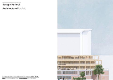
Architecture Portfolio
A collection of Academic & Professional works - 2019 - 2023 Email - jkuforiji76@gmail.com Phone number - 07848874448
Joseph Kuforiji

Joseph Kuforiji - Part 1 Architectural Assistant 02 1 Contents 2 3 4 5
01
Art- Sketches/Digital Art works
BA3- Design Sythensis
BA3- Design Preperation
Email - jkuforiji76@gmail.com Phone number - 07848874448
BA1- Pottery Studio Year Out - James Potter Associates
Year Out - James Potter Associates
For my Part 1 Architecture Year out, I was glad to work with James Potter’s Associates where I was able to take part in many residential and site planning schemes, as well as work as part of a design team, helping build both my architectrual and professional knowledge.
BA1 - Pottery Studio 04
03 Email - jkuforiji76@gmail.com Phone number - 07848874448
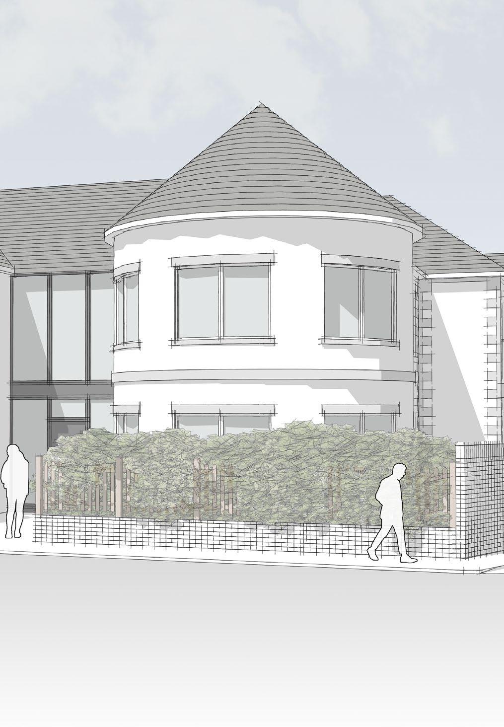
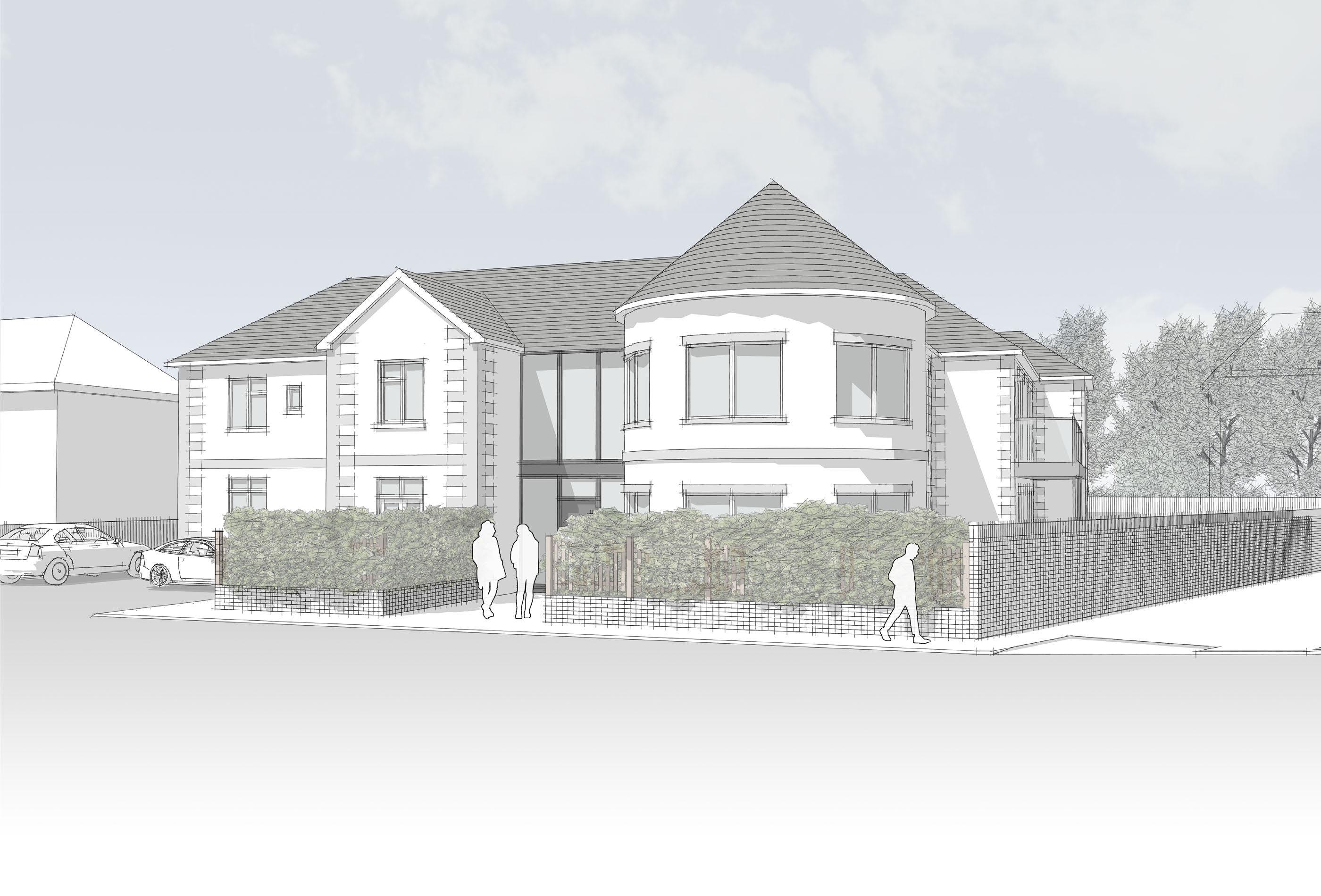
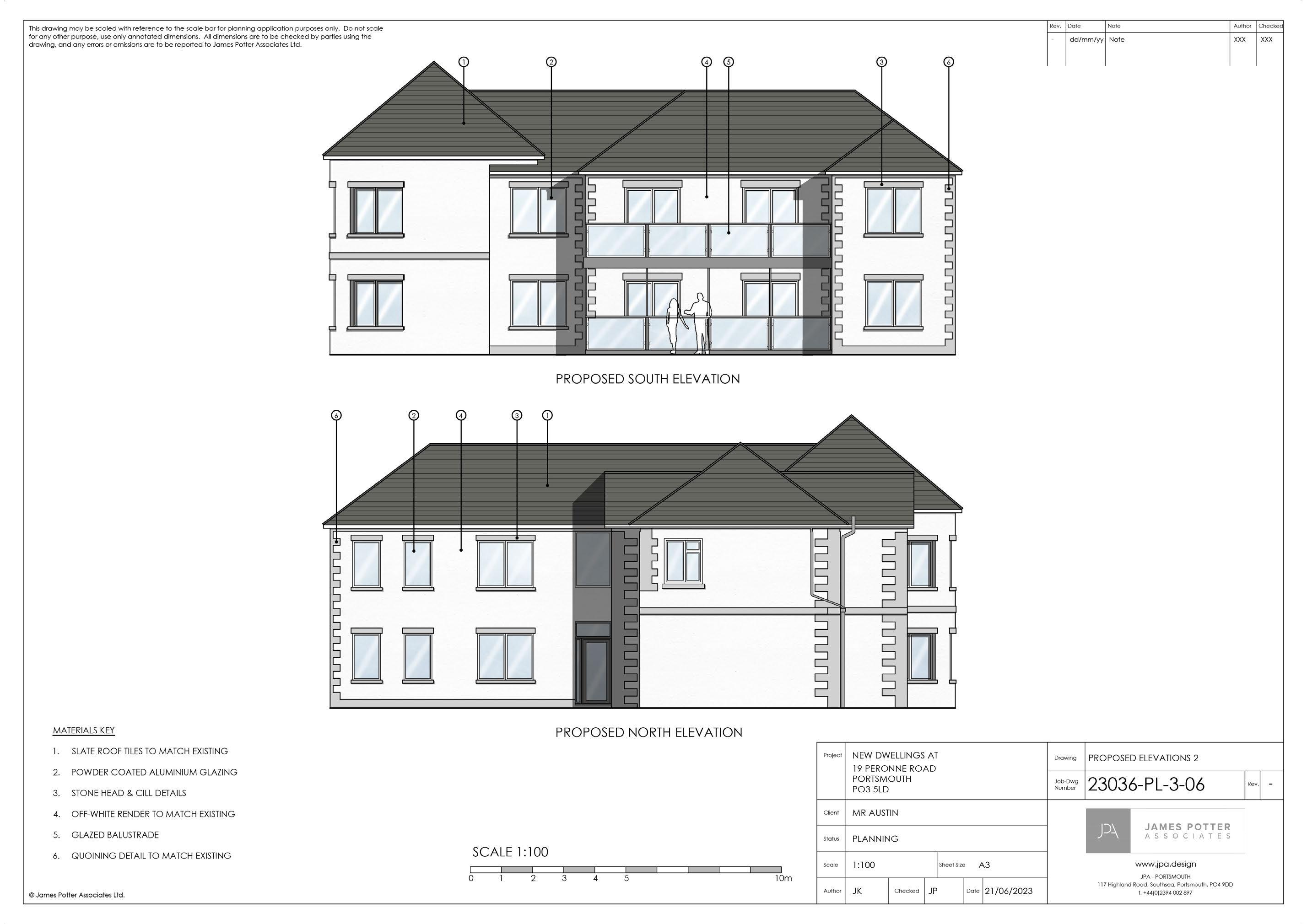
Project type: Private residential scheme
Project Scope:
Location: Portsmouth PO3 5LD
Involvement: Stages 1 - 3
Proposed
Existing ground floor plan
Existing first floor plan
Proposed West Elevation
Proposed East Elevation
Proposed Ground floor plan
was responsilbe for:
- Building upon the initial design to create the proposed sketch scheme.
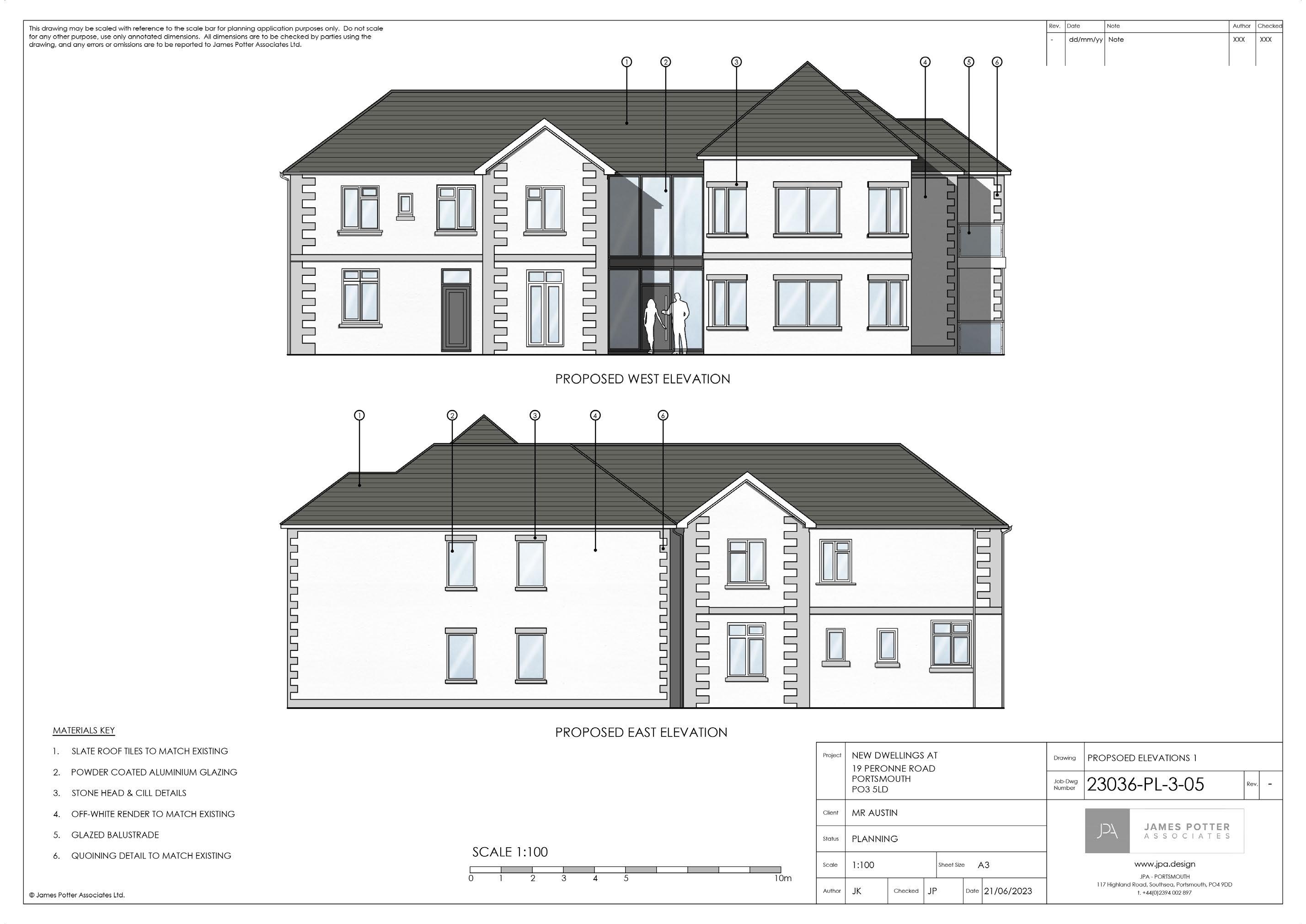
- Creating the proposed planning scheme following the meeting with the clients.
- Producing the CAD drawings.
- Producing the Indicative 3d visual.
Proposed North Elevation
JPA - James Potter Associate 19 Perrone Road new walls / partitions partitions BEDROOM 1 CPD. KITCHEN DINING LIVING BATHROOM LIVING BEDROOM 2 CPD. BEDROOM 1 COMMUNAL HALL BEDROOM 2 HALL HALL KITCHEN/DINING BEDROOM 2 KITCHEN LIVING/DINING CBD. HALL BEDROOM 1 BATHROOM BATHROOM SCHEDULE OF ACCOMMODATION No.2BEDA 2 Bed Flat 68m²(732 sqft) No.2BEDB 2 Bed Flat 70m²(753 sqft) No.2BEDC 2 Bed Flat 77m²(829 sqft) Total:6 UNITS Allocated Parking: 6 Spaces Un-allocated Parking: 2 Spaces Total Parking: 8 Spaces dd/mm/yy NoteRev.DateNote Status Project Scale Client Sheet Size Drawing Job-Dwg Number www.jpa.design planning application purposes only. Do not scale dimensions are to be checked by parties using the James Potter Associates Ltd. JPA PORTSMOUTH NEW DWELLINGS AT 19 PERONNE ROAD PORTSMOUTH PO3 5LD MR AUSTIN PROPSOED GROUND FLOOR PLAN 23036-PL-3-03 A3 1:100 PLANNING PROPOSED GROUND FLOOR PLAN 2BEDA FLAT 1 68m2 (732 sqft) NORTH SCALE 1:100 0 1 234 5 10m 2BEDB FLAT 3 70m2 (753 sqft) 2BEDC FLAT 5 77m2 (829 sqft) Existing walls partitions KEY KITCHEN W/C UTILITY DINING LIVING BEDROOM HALL BEDROOM 1 BEDROOM 2 BEDROOM W/C BATHROOM LANDING CPD. Rev. Status Project Scale Author Client Checked Sheet Size Date Drawing Job-Dwg Number www.jpa.design © James Potter Associates Ltd. JPA PORTSMOUTH 117 Highland Road, Southsea, Portsmouth, PO4 9DD +44(0)2394 002 897 NEW DWELLINGS AT 19 PERONNE ROAD PORTSMOUTH PO3 5LD MR AUSTIN EXSITING FLOOR PLANS 23036-PL-3-01 A3 JK 21/06/2023 1:100 PLANNING JPEXISTING GROUND FLOOR PLAN EXISTING FIRST FLOOR PLAN 0 1 234 5 10m 1:100 NORTH
South Elevation
05 Email - jkuforiji76@gmail.com Phone number - 07848874448
Project type: Private residential scheme, Rear/Loft Extension.
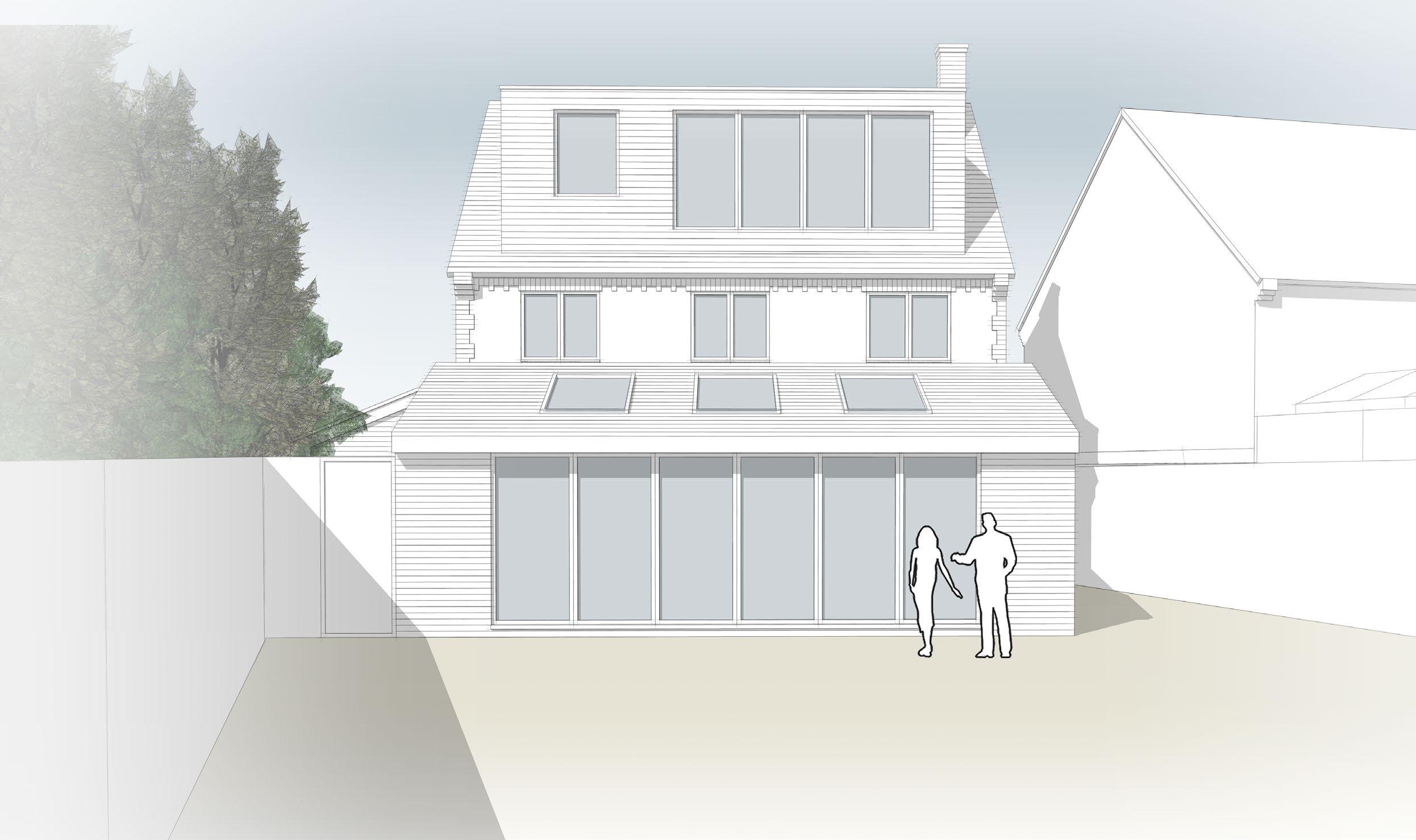
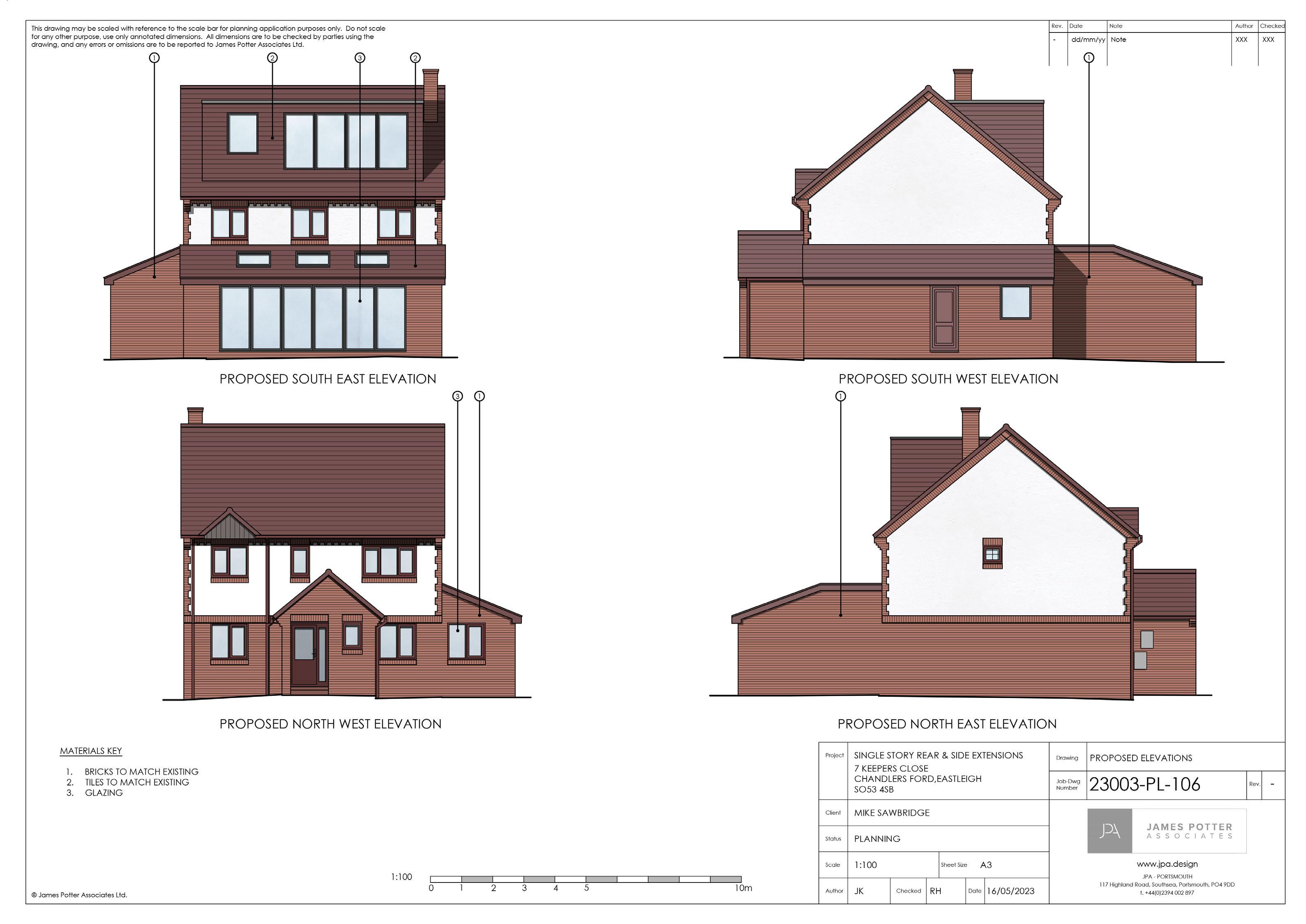
Location: Chandlers Ford Eastleigh, S053 4SB
Involvement: Stages 1 - 3
was responsilbe for:


- Building upon the initial design to create the proposed sketch scheme.
- Being involved with the meeting with the client discussing the sketch scheme and design changes.
- Creating the proposed planning scheme following the meeting with the clients.
- Producing the CAD drawings and Indicative 3d visuals.
08 7 Keepers Close KITCHEN DINING STUDY LIVING UTILITY ROOM PORCH W/C HALL CONSERVATORY Roof light above Proposed new walls / partitions Proposed structural lintels & beams Existing walls / partitions Boundary line PLAYROOM W/C KITCHEN OFFICE DINING HIDDEN LARDER LIVING LOUNGE UTILITY MEDIA WALL BOILER 2095 1505 4600 dd/mm/yy Note XXXXXXRev. Rev.DateNote AuthorChecked Status Project Scale Author Client Checked Sheet Size Date Drawing Job-Dwg Number www.jpa.design reference to the scale bar for planning application purposes only. Do not scale annotated dimensions. All dimensions are to be checked by parties using the omissions are to be reported to James Potter Associates Ltd. JPA PORTSMOUTH 117 Highland Road, Southsea, Portsmouth, PO4 9DD +44(0)2394 002 897 SINGLE STORY REAR & SIDE EXTENSIONS 7 KEEPERS CLOSE CHANDLERS FORD,EASTLEIGH SO53 4SB MIKE SAWBRIDGE GROUND FLOOR PLANS 23003-PL-102 A3 JK 16/05/2023 1:100 PLANNING RH5 10m EXISTING GROUND FLOOR PLAN PROPOSED GROUND FLOOR PLAN KITCHEN DINING STUDY LIVING UTILITY ROOM PORCH W/C HALL CONSERVATORY Roof light above Proposed new walls / partitions Proposed structural lintels & beams Existing walls / partitions KEY Boundary line PLAYROOM W/C KITCHEN OFFICE DINING HIDDEN LARDER LIVING LOUNGE UTILITY MEDIA WALL BOILER 2095 1505 4600 dd/mm/yy Note XXXXXXRev. Rev.DateNote AuthorChecked Project Scale Author Client Checked Sheet Size Date Drawing Job-Dwg Number www.jpa.design Potter Associates Ltd. may be scaled with reference to the scale bar for planning application purposes only. Do not scale other purpose, use only annotated dimensions. All dimensions are to be checked by parties using the and any errors or omissions are to be reported to James Potter Associates Ltd. JPA PORTSMOUTH 117 Highland Road, Southsea, Portsmouth, PO4 9DD t. +44(0)2394 002 897 SINGLE STORY REAR & SIDE EXTENSIONS 7 KEEPERS CLOSE CHANDLERS FORD,EASTLEIGH SO53 4SB MIKE SAWBRIDGE GROUND FLOOR PLANS 23003-PL-102 A3 JK 16/05/2023 1:100 PLANNING RH234 5 10m EXISTING GROUND FLOOR PLAN PROPOSED GROUND FLOOR PLAN
1800 1800 1800 1800 Roof light above Proposed new walls / partitions Proposed structural lintels & beams Existing walls / partitions KEY DRESSING ROOM ENSUITE BEDROOM 5 1800 1800 dd/mm/yy Note XXXXXXRev. Rev.DateNote AuthorChecked Status Project Client Drawing Job-Dwg Number may be scaled with reference to the scale bar for planning application purposes only. Do not scale purpose, use only annotated dimensions. All dimensions are to be checked by parties using the and any errors or omissions are to be reported to James Potter Associates Ltd. SINGLE STORY REAR & SIDE EXTENSIONS 7 KEEPERS CLOSE CHANDLERS FORD,EASTLEIGH SO53 4SB MIKE SAWBRIDGE LOFT PLANS 23003-PL-104 PLANNINGEXISTING LOFT PLAN PROPOSED LOFT PLAN 1800 1800 1800 1800 Roof light above Proposed new walls / partitions Proposed structural lintels & beams Existing walls / partitions DRESSING ROOM ENSUITE BEDROOM 5 1800 1800 dd/mm/yy Note XXXXXXRev. Rev.DateNote AuthorChecked Status Project Client Drawing Job-Dwg Number reference to the scale bar for planning application purposes only. Do not scale annotated dimensions. All dimensions are to be checked by parties using the omissions are to be reported to James Potter Associates Ltd. SINGLE STORY REAR & SIDE EXTENSIONS 7 KEEPERS CLOSE CHANDLERS FORD,EASTLEIGH SO53 4SB MIKE SAWBRIDGE LOFT PLANS 23003-PL-104 PLANNINGEXISTING LOFT PLAN PROPOSED LOFT PLAN Indicative 3D Visual Proposed West Elevation Proposed South Elevation Proposed ground floor plan Existing ground floor plan
loft plan Existing loft plan
Proposed
07 Email - jkuforiji76@gmail.com Phone number - 07848874448
Project Type: Private residential scheme, Rear/Side Extension.
Location: Westbourne, Emsworth PO10 8TH
Involvement: Stage 4
Joist floor plan
I was responsilbe for:
First floor plan
- Assisting the lead architectural designer in drawing the structural plans and sections.
JPA - James Potter Associate 10 28 Mill Road New foundation New non-loadbearing partition over Denotes 2.9N/mm² aircrete wall blocks (Density to be 460-800kg/m³ and Thermal Conductivity of 0.11W/mK - Refer to Notes / Structural Engineers details & design. Denotes 3.6N/mm² aggregate wall blocks (Density to Denotes facing brick Refer to Refer to Notes Structural Engineers details & design. Steel beam to Structural Engineers details & design Concrete Lintel to Structural Engineers details & design Timber structural members flitch beam, ridge beam or multiple rafters/joists bolted together to Structural Engineers details & design New non-loadbearing partition below PLANS LEGEND Steel Beam with Plate to u/s to support masonry outer skin to Structural Engineers details design Steel Beam with Plate to top to support masonry outer skin to Structural Engineers details design Electric service entry route Telecom service entry route Gas service entry route Water service entry route Indicative location of 215x65mm Air brick connected to telescopic void ventilator. Foul water drainage route Surface water drainage route New non-loadbearing masonry wall over New non-loadbearing masonry wall below New loadbearing masonry wall over Steel Lintel to Structural Engineers details & design Denotes 3.6N/mm² dense concrete foundation blocks Refer to Notes Structural Engineers details design. New structural studwork wall over Denotes 3.6N/mm² aggregate wall blocks (Density to be 1350-1600 kg/m³) Refer to Notes Structural Engineers details & design. Denotes 7.3N/mm² lightweight aggregate wall blocks (Density to be 1400-1800kg/m³) Refer to Notes Structural Engineers details & design. Outside floor to be lowered and finish to be on paving support system. Structural Studwork to Structural Engineer's details Direction of flat roof joists. Refer to Specification, Structural Engineers and manufacturers design and details Direction of pitched roof rafters. Refer to Specification, Structural Engineers and manufacturers design and details Direction of beam and block floor beams. Refer to Specification, Structural Engineers and manufacturers design and details S H CO Ceiling mounted extract fan indicative ducting route EF Carbon Monoxide detector battery operated (Only required Gas fuel used for cooking or heating) Fully automatic smoke detector to BS EN 14604:2005 (minimum 2No.). Interlinked and hardwired to mains Fully automatic heat detector to BS 5446-2:2003 Interlinked and hardwired to mains Wall mounted extract fan Tile Vent (SVP or Extract as noted) Direction and angle of roof fall 27.5° PITCH Rainwater downpipe Soil Vent Pipe Foul water internal drainage routes Gas point for Boiler & Cooker Door & Window References (Refer to schedules for sizes) (i)Door/Window Type ED= External Door ID= Internal Door W= Window (ii)00= Ground Floor (iii)Door/Window Number (i) (ii) (iii) ED-00-## Direction of timber floor joists. Refer to Specification, Structural Engineers and manufacturers design and details Existing floor Remedial action to be taken for variations adjacent floor levels occuring to achieve level finished floor Existing floor Remedial action to be taken for variations in adjacent floor levels occuring to achieve level finished floor Existing walls taken down below existing floor finish level to enable installation of new floor over (level subject to floor construction) Existing conservatory walls, floor and foundations removed Existing floor Remedial action to be taken for variations adjacent floor levels occuring to achieve level finished floor Ground Floor (Beam and Block) Refer to Notes Ground Floor (Beam and Block) Refer to Notes Outside floor to be lowered and finish to be on paving support system. Outside floor to be lowered and finish to be on paving support system. Existing Floor Waste connection for kitchen exact location to be confirmed WHB direct connection WC direct connection A A B B EXISTING SVP LOCATION SHOWN INDICATIVELY. DRAINAGE TO BE RE-ROUTED. EXACT ROUTE TO BE CONFIRMED ON SITE 1350 440 910 4000 552.5 2400 552.5 797.5 665 Post to structural engineer's design Post to structural engineer's design Posts to structural engineer's design Post to structural engineer's design LOUNGE OFFICE SNUG CPD. HALL UTILITY W/C LARDER Structural studwork to Structural Engineer's details Non-loadbearing partition Refer to Notes Beams and Pad stones to Structural Engineers design Beams and Pad stones to Structural Engineers design Flat Roof Light over to Client Specification Flat Roof Light over to Client Specification External Wall Brickwork Refer to Notes Utility and Associated Layouts to Specialist Design WC Associated Layouts Specialist Design Larder and Associated Layouts to Specialist Design Window Refer to Notes Sliding doors Refer to Notes Position of waste connection for kitchen to be confirmed A A B B RWP RWP F Beams and Pad stones to Structural Engineers design F Kitchen Associated Layouts to Specialist Design KITCHEN DINING ED-00-01 ED-00-02 ID-00-01 ID-00-02 ID-00-03 ID-00-04 ID-00-05 ID-00-06 W-00-01 W-00-02 RL-01-01 RL-01-02 Post to structural engineer's design External Wall Brickwork Refer to Notes Window Refer to notes EXISTING SVP LOCATION SHOWN INDICATIVELY. DRAINAGE TO BE RE-ROUTED. EXACT ROUTE TO BE CONFIRMED ON SITE 1350 440 910 4000 552.5 2400 552.5797.5 665 838door 838door FD30S-SC 762door 762door 533door FD30 686door 838door FD30S-SC S H Existing chimney breast removed at ground floor level Steel beam to structural engineer's design. Extent and location of plate to be confirmed by structural engineer Post to structural engineer's design Post to structural engineer's design Posts to structural engineer's design Beam to structural engineer's design Beam to structural engineer's design Structural studwork to Structural Engineer's details Blockwork infill. Exact details/specificaion tbc on site FOR EXISTING PLANS REFER TO DRAWING 22024-BR-X-01, FOR CONSTRUCTION NOTES REFER TO DRAWING 22024-BR-0-01, FOR SCHEDULES REFER TO DRAWING 22024-BR-0-02, FOR PLANS REFER TO DRAWINGS 22024-BR-3-01,22024-BR-3-02 & 22024-BR-3-03 FOR SECTIONS REFER TO DRAWINGS 22024-BR-4-01, FOR ELEVATIONS REFER TO DRAWING 22024-BR-5-01. Rev.DateNote AuthorChecked Rev. Status Project Scale Author Client Checked Sheet Size Date Drawing Job-Dwg Number James Potter Associates Ltd. drawing may be scaled with reference to the scale bar for planning application purposes only. Do not scale other purpose, use only annotated dimensions. All dimensions are to be checked by parties using the drawing, and any errors or omissions are to be reported to James Potter Associates Ltd. www.jpa.design JPA PORTSMOUTH 117 Highland Road, Southsea, Portsmouth, PO4 9DD +44(0)2394 002 897 PLANS SUBSTRUCTURE AND GROUND FL 22024-BR-3-01 C REAR/SIDE EXTENSION 28 MILL ROAD WESTBOURNE, EMSWORTH PO10 8TH MR MATT HUMPHREYS & MS BETH WATTS BUILDING REGULATIONS 1:50 (1:100 @ A3) A1 JK AJ 06/02/2023 10/02/2023Steelwork at first floor joist level to support chimney breast (retained) above. JHJP SUBSTRUCTURE PLAN SCALE 1:50 GROUND FLOOR PLAN SCALE 1:50 14/06/2023 Posts to Structural Engineer's design added as clouded. AJ 16/06/2023 Drawing updated to suit Structural Engineer's information as clouded. AJ C KITCHEN External Wall (Facing Brickwork) - Refer to Notes Rooflight to specialist design Ground Floor (Beam and block) Refer to Notes Foundation Refer to Notes Internal Non Load-bearing Partition - Refer to Notes Flat Roof (Extension) Refer to Notes Beams and Pad stones to Structural Engineers design Outside floor to be lowered and finish to be on paving support system. 150mm min upstand at parapet 150mm min upstand at rooflight perimeter © James Potter Associates Ltd. SECTION AA SCALE 1:50 KITCHEN External Wall (Facing Brickwork) - Refer to Notes Rooflight to specialist design Ground Floor (Beam and block) Refer to Notes Foundation Refer to Notes Internal Non Load-bearing Partition - Refer to Notes Flat Roof (Extension) Refer to Notes Beams and Pad stones to Structural Engineers design Outside floor to be lowered and finish to be on paving support system. 150mm min upstand at parapet 150mm min upstand at rooflight perimeter Foundation Refer to Notes Foundation Refer to Notes External Wall (Facing Brickwork) - Refer to Notes Ground Floor (Beam and Block) Refer to Notes Flat Roof (Extension) Refer to Notes W/C LARDER Internal Non Load-bearing Partition - Refer to Notes DoorRefer to Notes Rooflight to specialist design Window - Refer to Notes RWO to Hopper to RWP (Harmer 2Way or similar) Wall hung toilet with internal pipe Beams and Pad stones to Structural Engineers design Outside floor to be lowered and finish to be on paving support system. 150mm min upstand at parapet Rev.DateNote AuthorChecked This drawing may be scaled with reference to the scale bar for planning application purposes only. Do not scale for any other purpose, use only annotated dimensions. All dimensions are to be checked by parties using the drawing, and any errors or omissions are to be reported to James Potter Associates Ltd. SECTION AA SCALE 1:50 SECTION BB SCALE 1:50 **/**/**** **** **** partition over aircrete wall blocks (Density to be Thermal Conductivity of 0.11W/mK Structural Engineers details & design. aggregate wall blocks (Density to Refer to Refer to Notes details & design. Structural Engineers details & design Structural Engineers details & design members flitch beam, ridge beam bolted together to Structural design partition below to u/s to support masonry outer Engineers details design to top to support masonry outer Engineers details design route route route route connected ventilator. route drainage route masonry wall over masonry wall below masonry wall over Structural Engineers details & design dense concrete foundation blocks Structural Engineers details design. studwork wall over Denotes 3.6N/mm² aggregate wall blocks (Density to be 1350-1600 kg/m³) Refer to Notes Structural Engineers details & design. Denotes 7.3N/mm² lightweight aggregate wall blocks (Density to be 1400-1800kg/m³) Refer to Notes Structural Engineers details & design. Outside floor to be lowered and finish to be on paving support system. Structural Studwork to Structural Engineer's details Direction of flat roof joists. Refer to Specification, Structural Engineers and manufacturers design and details Direction of pitched roof rafters. Refer to Specification, Structural Engineers and manufacturers design and details Direction of beam and block floor beams. Refer to Specification, Structural Engineers and manufacturers design and details S H CO Ceiling mounted extract fan indicative ducting route EF Carbon Monoxide detector battery operated (Only required Gas fuel used for cooking or heating) Fully automatic smoke detector to BS EN 14604:2005 (minimum 2No.). Interlinked and hardwired to mains Fully automatic heat detector to BS 5446-2:2003 Interlinked and hardwired to mains Wall mounted extract fan Tile Vent (SVP or Extract as noted) Direction and angle of roof fall 27.5° PITCH Rainwater downpipe Soil Vent Pipe Foul water internal drainage routes Gas point for Boiler & Cooker Door & Window References (Refer to schedules for sizes) (i)Door/Window Type ED= External Door ID= Internal Door W= Window (ii)00= Ground Floor (iii)Door/Window Number (i) (ii) (iii) ED-00-## Direction of timber floor joists. Refer to Specification, Structural Engineers and manufacturers design and details floor Remedial action to be variations adjacent floor levels to achieve level finished floor Existing floor Remedial action to be for variations in adjacent floor levels occuring to achieve level finished floor Existing walls taken down below existing floor finish level to enable installation of new floor over (level subject to floor construction) Existing conservatory walls, floor and foundations removed Existing floor Remedial action to be taken for variations adjacent floor levels occuring to achieve level finished floor Ground Floor (Beam and Block) Refer to Notes Ground Floor (Beam and Block) Refer to Notes Outside floor to be lowered and finish to be on paving support system. Outside floor to be lowered and finish to be on paving support system. Existing Floor Waste connection for kitchen exact location to be confirmed WHB direct connection WC direct connection A B B EXISTING SVP LOCATION SHOWN INDICATIVELY. DRAINAGE TO BE RE-ROUTED. EXACT ROUTE TO BE CONFIRMED ON SITE 1350 440 910 4000 552.5 2400 552.5797.5 665 structural engineer's to structural engineer's design Posts to structural engineer's design Post to structural engineer's design LOUNGE OFFICE SNUG CPD. HALL UTILITY W/C LARDER Structural studwork to Structural Engineer's details Non-loadbearing partition Refer to Notes Beams and Pad stones to Structural Engineers design Beams and Pad stones to Structural Engineers design Flat Roof Light over to Client Specification Flat Roof Light over to Client Specification External Wall Brickwork Refer to Notes Utility and Associated Layouts to Specialist Design WC Associated Layouts Specialist Design Larder and Associated Layouts to Specialist Design Window Refer to Notes Sliding doors Refer to Notes Position of waste connection for kitchen to be confirmed A A B B RWP RWP F Beams and Pad stones to Structural Engineers design F Kitchen Associated Layouts to Specialist Design KITCHEN DINING ED-00-01 ED-00-02 ID-00-01 ID-00-02 ID-00-03 ID-00-04 ID-00-05 ID-00-06 W-00-01 W-00-02 RL-01-01 RL-01-02 Post to structural engineer's design External Wall Brickwork Refer to Notes Window Refer to notes EXISTING SVP LOCATION SHOWN INDICATIVELY. DRAINAGE TO BE RE-ROUTED. EXACT ROUTE TO BE CONFIRMED ON SITE 1350 440 910 4000 552.5 2400 552.5 797.5 665 838door 838door FD30S-SC 762door 762door 533door FD30 838door FD30S-SC S H Existing chimney breast removed at ground floor level Steel beam to structural engineer's design. Extent and location of plate to be confirmed by structural engineer Post to structural engineer's design Post to structural engineer's design Posts to structural engineer's design Beam to structural engineer's design Beam to structural engineer's design Structural studwork to Structural Engineer's details Blockwork infill. Exact details/specificaion tbc on site FOR EXISTING PLANS REFER TO DRAWING 22024-BR-X-01, FOR CONSTRUCTION NOTES REFER TO DRAWING 22024-BR-0-01, FOR SCHEDULES REFER TO DRAWING 22024-BR-0-02, FOR PLANS REFER TO DRAWINGS 22024-BR-3-01,22024-BR-3-02 & 22024-BR-3-03 FOR SECTIONS REFER TO DRAWINGS 22024-BR-4-01, FOR ELEVATIONS REFER TO DRAWING 22024-BR-5-01. Rev. Status Project Scale Author Client Checked Sheet Size Date Drawing Job-Dwg Number purposes only. Do not scale parties using the www.jpa.design JPA PORTSMOUTH 117 Highland Road, Southsea, Portsmouth, PO4 9DD +44(0)2394 002 897 PLANS SUBSTRUCTURE AND GROUND FL 22024-BR-3-01 C REAR/SIDE EXTENSION 28 MILL ROAD WESTBOURNE, EMSWORTH PO10 8TH MR MATT HUMPHREYS & MS BETH WATTS BUILDING REGULATIONS 1:50 (1:100 @ A3) A1 JK AJ 06/02/2023 10/02/2023Steelwork at first floor joist level to support chimney breast (retained) above. JHJP SUBSTRUCTURE PLAN 1:50 GROUND FLOOR PLAN SCALE 1:50 14/06/2023 Posts to Structural Engineer's design added as clouded. AJ 16/06/2023 Drawing updated to suit Structural Engineer's information as clouded. AJ C
Substructure plan Ground floor plan
Section AA Section BB RWP RWP Flat Roof Light to be AA, AB, AC fire rated Insulated Upstand Flat Roof Light to be AA, AB, AC fire rated Insulated Upstand Flat Roof (Warm Roof) - Refer to Notes RWO to Hopper to RWP (Harmer 2Way or similar) RWO to Hopper to RWP (Harmer 2Way or similar) A A B B Steel beam to structural engineer's design. Extent and location of plate to be confirmed by structural engineer EXISTING SVP LOCATION SHOWN INDICATIVELY. DRAINAGE TO BE RE-ROUTED. EXACT ROUTE TO BE CONFIRMED ON SITE BEDROOM 2 BEDROOM 1 BEDROOM 3 EAVE STORAGE BATHROOM CPD. LANDING EXTENDED TO SAME DISTANCE AS NEIGHBOURS Flat Roof Light to be AA, AB, AC fire rated & Insulated Upstand Flat Roof Light to be AA, AB, AC fire rated & Insulated Upstand Flat Roof (Warm Roof) - Refer to Notes RWP RWP RWO to Hopper to RWP (Harmer 2Way similar) RWO to Hopper to RWP (Harmer 2Way or similar) A A B B EXISTING SVP LOCATION SHOWN INDICATIVELY. DRAINAGE TO BE RE-ROUTED. EXACT ROUTE TO BE CONFIRMED ON SITE S Existing chimney breast retained at first floor level and above New foundation New non-loadbearing partition over New non-loadbearing partition below PLANS LEGEND Electric service entry route Telecom service entry route Gas service entry route Water service entry route Indicative location of 215x65mm Air brick connected to telescopic void ventilator. Foul water drainage route Surface water drainage route New non-loadbearing masonry wall over New non-loadbearing masonry wall below New loadbearing masonry wall over New structural studwork wall over Denotes 3.6N/mm² aggregate wall blocks (Density to be 1350-1600 kg/m³) Refer to Notes Structural Engineers details & design. Denotes 7.3N/mm² lightweight aggregate wall blocks (Density to be 1400-1800kg/m³) Refer to Notes Structural Engineers details & design. Outside floor to be lowered and finish to be on paving support system. Structural Studwork to Structural Engineer's details Direction of flat roof joists. Refer to Specification, Structural Engineers and manufacturers design and details Direction of pitched roof rafters. Refer to Specification, Structural Engineers and manufacturers design and details Direction of beam and block floor beams. Refer to Specification, Structural Engineers and manufacturers design and details S Ceiling mounted extract fan & indicative ducting route F EF Fully automatic smoke detector to BS EN 14604:2005 (minimum 2No.). Interlinked and hardwired to mains Wall mounted extract fan Gas point for Boiler Cooker Direction of timber floor joists. Refer to Specification, Structural Engineers and manufacturers design and details Rev.DateNote AuthorChecked drawing may be scaled with reference to the scale bar for planning application purposes only. Do not scale other purpose, use only annotated dimensions. All dimensions are to be checked by parties using the and any errors or omissions are be reported to James Potter Associates Ltd. JOIST PLAN SCALE 1:50 FIRST FLOOR PLAN SCALE 1:50 10/02/2023Steelwork at first floor joist level to support chimney breast (retained) above. JHJP 14/06/2023 Posts to Structural Engineer's design added as clouded. AJ B 16/06/2023 Drawing updated to suit Structural Engineer's information as clouded. AJ C RWP RWP Flat Roof Light to be AA, AB, AC fire rated & Insulated Upstand Flat Roof Light be AA, AB, AC fire rated & Insulated Upstand Flat Roof (Warm Roof) - Refer to Notes RWO to Hopper to RWP (Harmer 2Way or similar) RWO to Hopper to RWP (Harmer 2Way or similar) A B B Steel beam to structural engineer's design. Extent and location of plate to be confirmed by structural engineer EXISTING SVP LOCATION SHOWN INDICATIVELY. DRAINAGE TO BE RE-ROUTED. EXACT ROUTE TO BE CONFIRMED ON SITE BEDROOM 2 BEDROOM 1 BEDROOM 3 EAVE STORAGE BATHROOM CPD. LANDING EXTENDED TO SAME DISTANCE AS NEIGHBOURS Flat Roof Light to be AA, AB, AC fire rated Insulated Upstand Flat Roof Light to be AA, AB, AC fire rated Insulated Upstand Flat Roof (Warm Roof) - Refer to Notes RWP RWP RWO to Hopper to RWP (Harmer 2Way or similar) RWO to Hopper to RWP (Harmer 2Way or similar) A A B B EXISTING SVP LOCATION SHOWN INDICATIVELY. DRAINAGE TO BE RE-ROUTED. EXACT ROUTE TO BE CONFIRMED ON SITE S Existing chimney breast retained at first floor level and above non-loadbearing partition over non-loadbearing partition below entry route entry route route entry route location of brick connected ventilator. drainage route drainage route non-loadbearing masonry wall over non-loadbearing masonry wall below masonry wall over studwork wall over Denotes 3.6N/mm² aggregate wall blocks (Density to be 1350-1600 kg/m³) Refer to Notes Structural Engineers details & design. Denotes 7.3N/mm² lightweight aggregate wall blocks (Density to be 1400-1800kg/m³) Refer to Notes Structural Engineers details & design. Outside floor to be lowered and finish to be on paving support system. Structural Studwork to Structural Engineer's details Direction of flat roof joists. Refer to Specification, Structural Engineers and manufacturers design and details Direction of pitched roof rafters. Refer to Specification, Structural Engineers and manufacturers design and details Direction of beam and block floor beams. Refer to Specification, Structural Engineers and manufacturers design and details Ceiling mounted extract fan & indicative ducting route F EF Fully automatic smoke detector to BS EN 14604:2005 (minimum 2No.). Interlinked and hardwired to mains Wall mounted extract fan Gas point for Boiler & Cooker Direction of timber floor joists. Refer to Specification, Structural Engineers and manufacturers design and details Rev.DateNote AuthorChecked purposes only. Do not scale checked by parties using the PLAN SCALE 1:50 FIRST FLOOR PLAN SCALE 1:50 10/02/2023Steelwork at first floor joist level to support chimney breast (retained) above. JHJP A 14/06/2023 Posts to Structural Engineer's design added as clouded. AJ 16/06/2023 Drawing updated to suit Structural Engineer's information as clouded. AJ C
09 Email - jkuforiji76@gmail.com Phone number - 07848874448
BA3 - Hybrid Building
BA3 - Design Sythensis 12
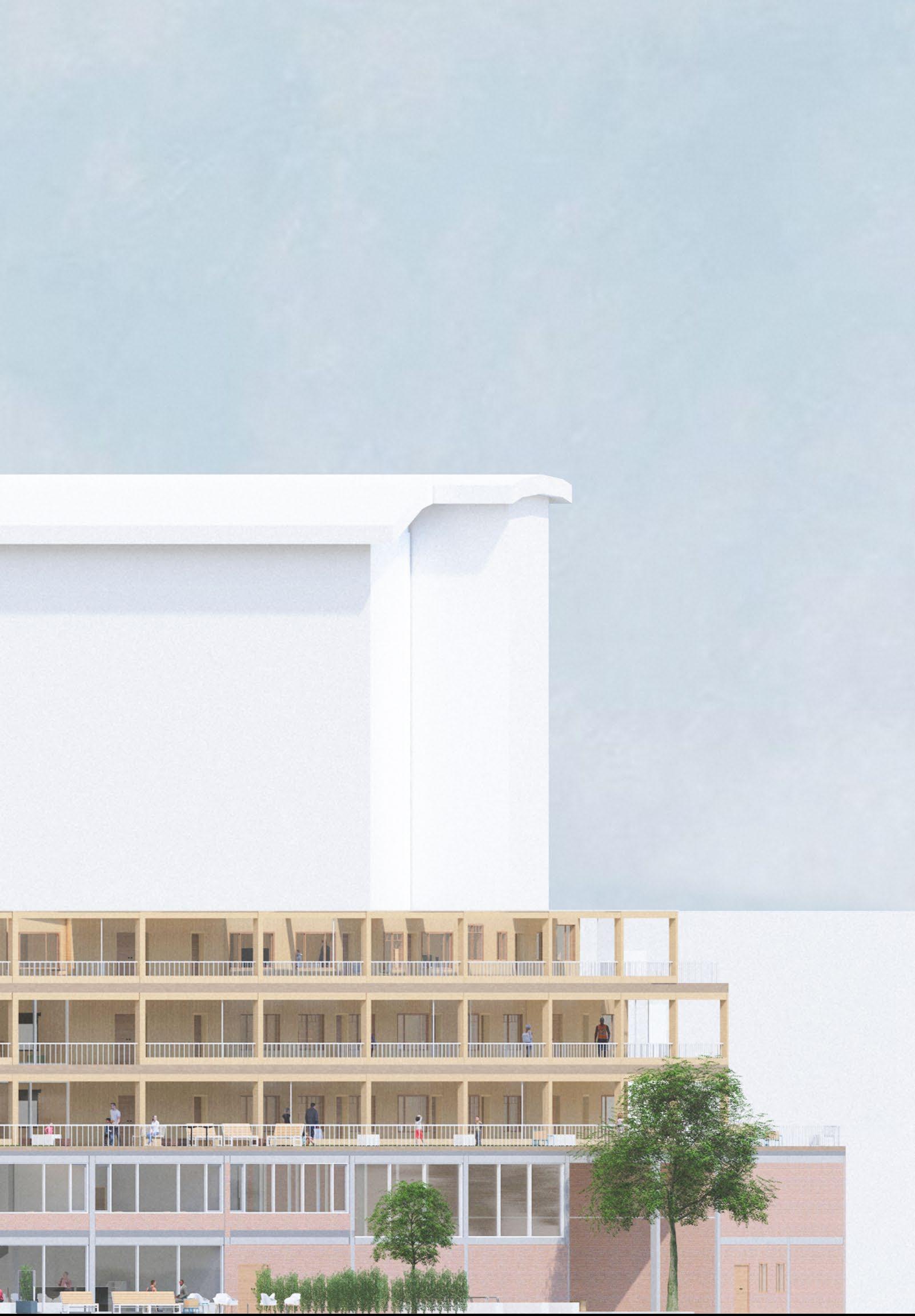
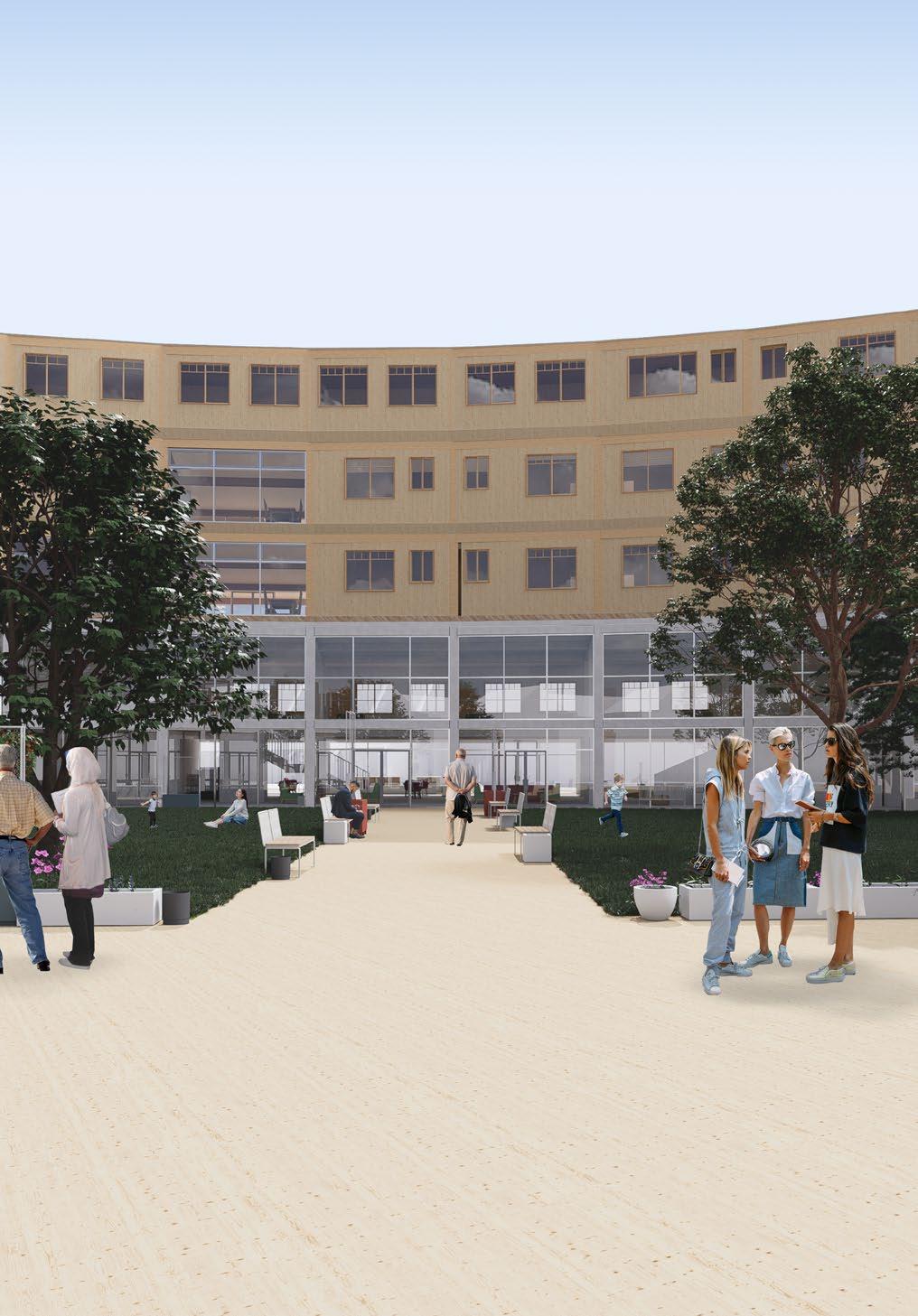
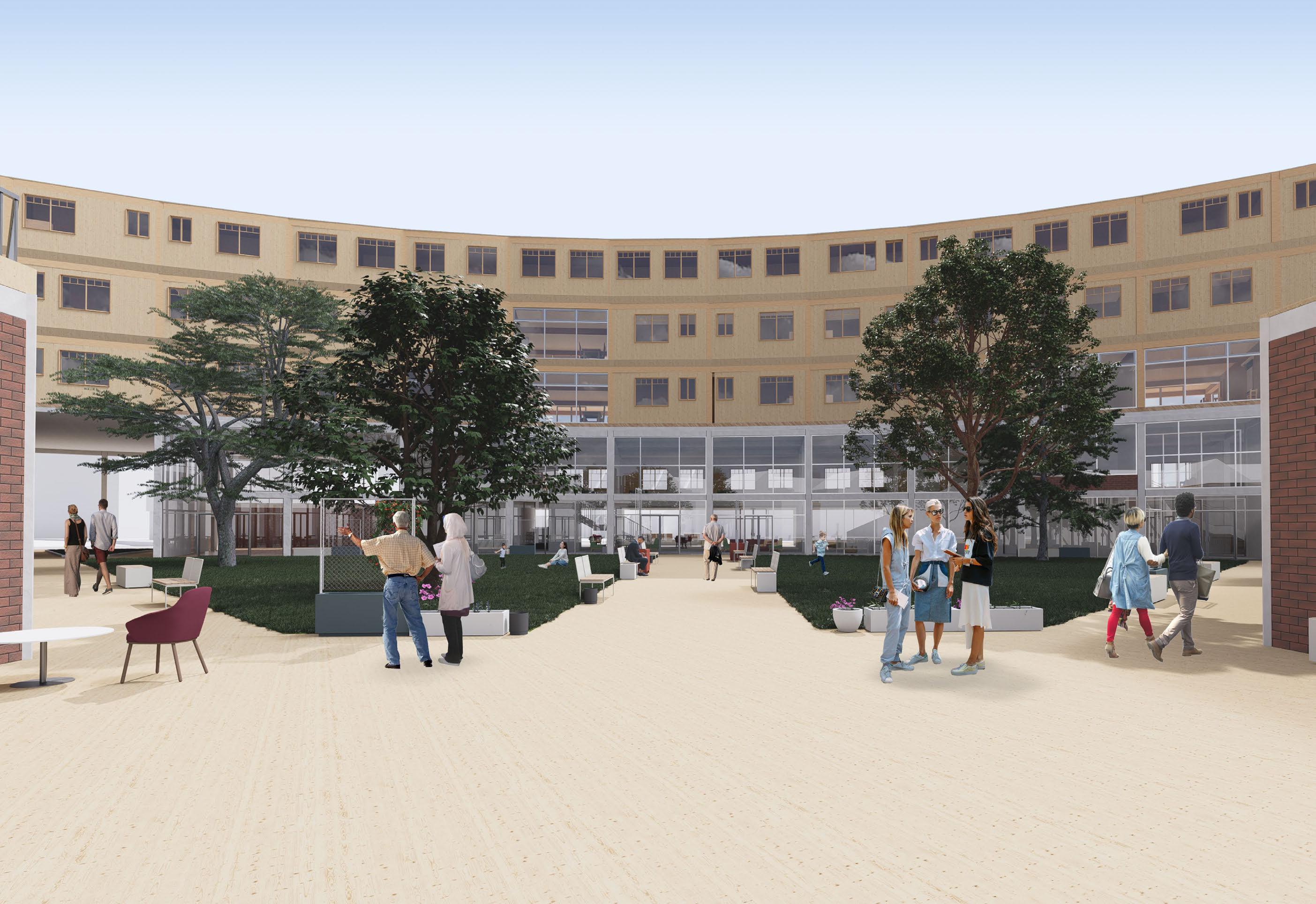
Located on Commercial Road city centre, the new hybrid building acts as an hub for all those in the area. The aim of project is to tackle and aid the lack of certain necessities in the local area,creating environments that the local community can make the most use off, while also providing affordable housing. This would give back to the local commiunity as well as new visitors to Portsmouth,
11 Email - jkuforiji76@gmail.com Phone number - 07848874448
1 - The site chosen is located near the centre of Commerical Road, close to main uses of the site.

2 - The form of the building chosen to allow entrace from the main access points of the site. Uses on the ground floor being uses that were missing in the sorrounding local community.
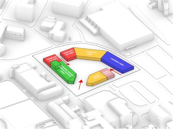
3 - Seperation of the public use and private residential.

Entertainment/ Community


DESIGN SYNTHESIS - HYBRID RESIDENTIAL
Earlier in the academic year we had a project which was set in the same area of commercial road, that project was a city planning and rejuvenation project with us analysing the commercial road area and looking at ways to revitalize it.
5 key points I focused on were the Education Entertainment Farmers Market Vegetation, and Community however a lack of Affordable Residential Housing was also an issue in the local area and this is an issue wanted to tackle within this project.
Grounded Approach
In order to understand what was needed in the local Commercial Road area to gain inspiration for the residential building, a few students and I booked a meeting with a local council member in order to gain more knowledge on what implementation would actually be important for the area and what focus would be key when building residential buildings in this area. She gave the advice to look to Portsmouth Planning guide and the Portsmouth Housing guide for helpful information
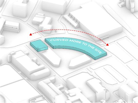
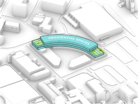
4 - Form of the building altered to fit the shape of the site.
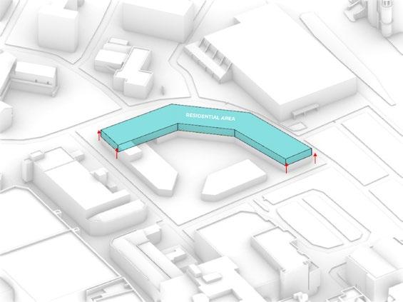
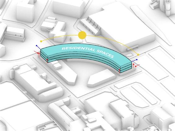
5 - Residential spaces seperated from the mixed use and positioned in increase expose to sunlight and privacy.
6 - Private gardens added to connect residents to nature and to providing more veigtation to the overall area.
BA3 - Design Sythensis 14
Farmers Market Education Homelessness Vegetation
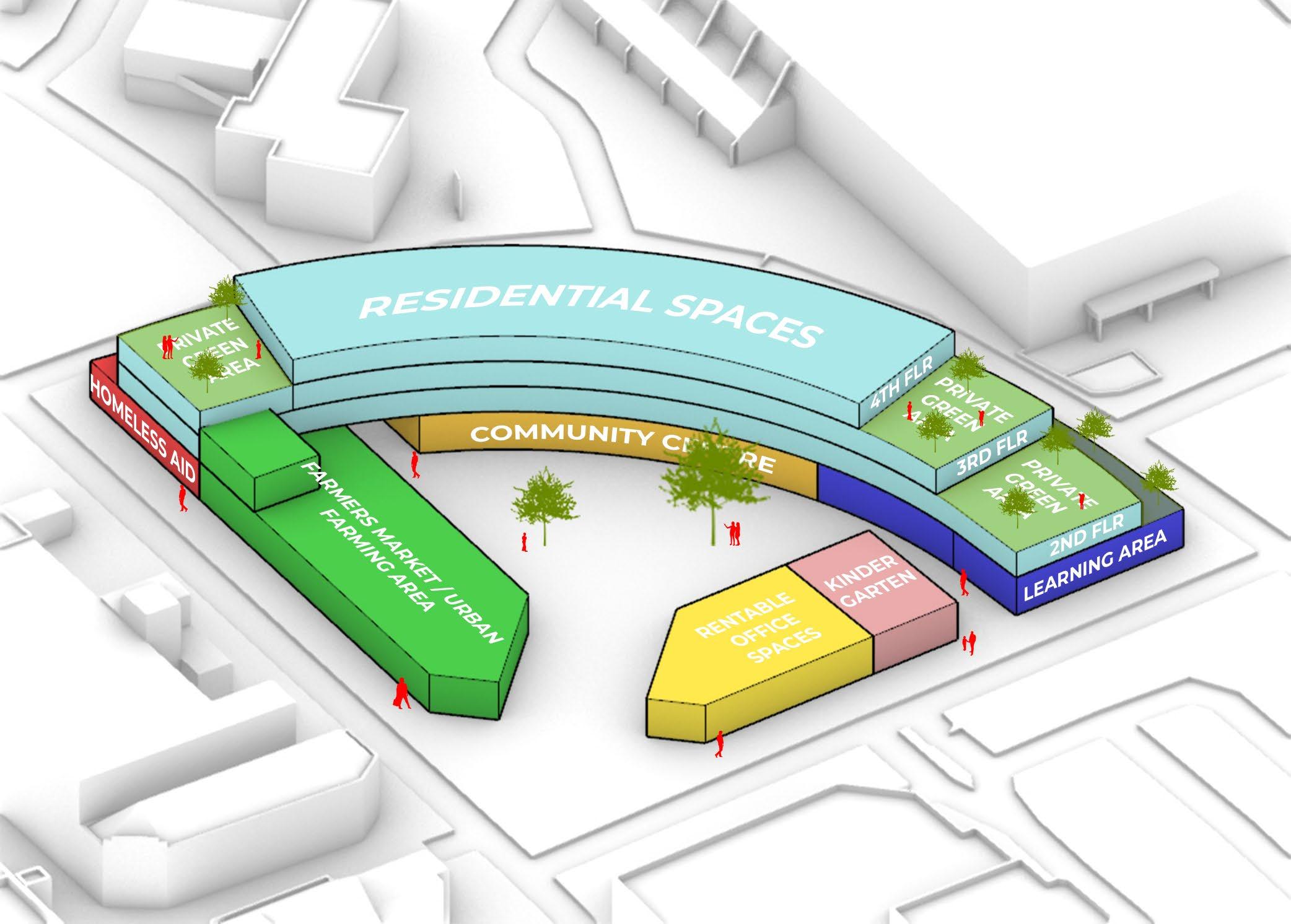
Programmatic Diagram 13 Email - jkuforiji76@gmail.com Phone number - 07848874448
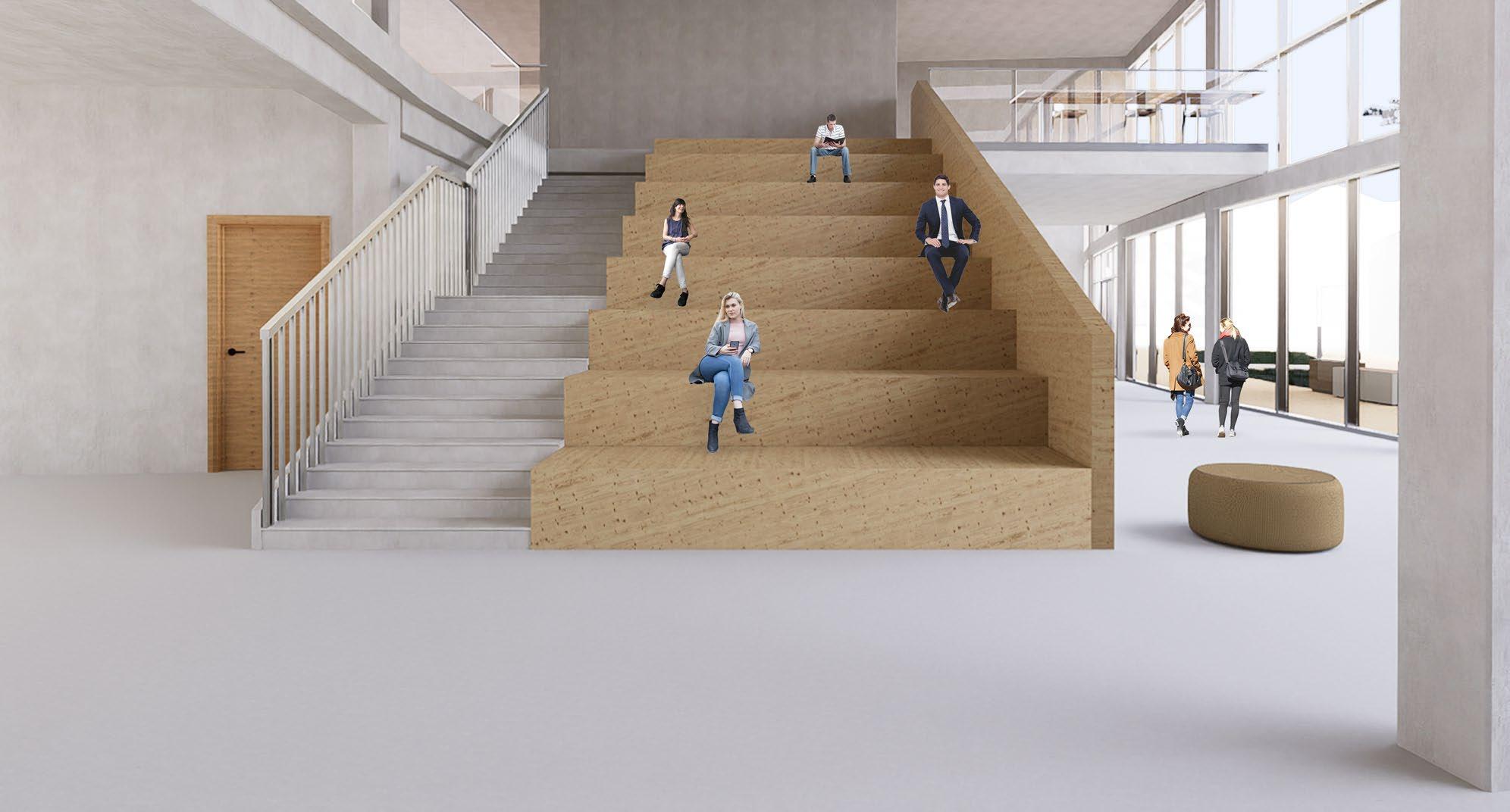
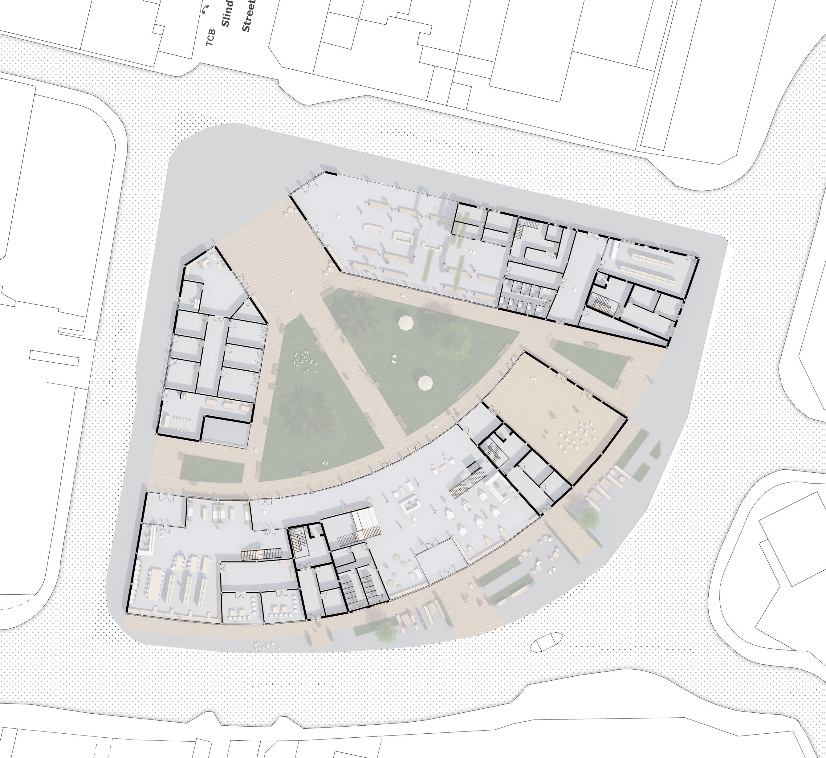
The ground floor plan showcases all the mixed use areas which are available to be used by the local Portsmouth community. The goal of the uses are to add to the local community creating areas which can be used by them, from rentable offices that smaller local business can use, to an central farmers market where the local farmers can sell their goods, to a library and an homeless aid area which local homeless can get items in which they need for free. The communal areas and atrium can also serve many uses such as a gynmasium or showcase hall. The hope is this scheme will bring a more unified area of community to an environment which currently doesn’t have one.


BA3 - Design Sythensis 16
1 - Public Entrance courtyard
2 - Communal area
3 - Cafe
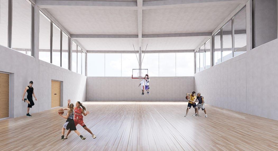
4 - Sports area
5 - Library
6 - Language learning area
7 - Food market area
8 - Bookable office spaces
9 - Kindergarten
10 - Food Bank
11 - Private Entrance to residential dwellings
12 - Bin storage
13 - Bike storage
1 7 14 10 12 13 11 4 12 13 11 3 2 12 13 11 6 5 9 8 15
14 - Toilets 15 - Courtyard
GF - Entrance/Communal area
GF - Showcase area
GF - Auditorium/Gymnasium
15 Email - jkuforiji76@gmail.com Phone number - 07848874448
Ground Floor
1st Floor
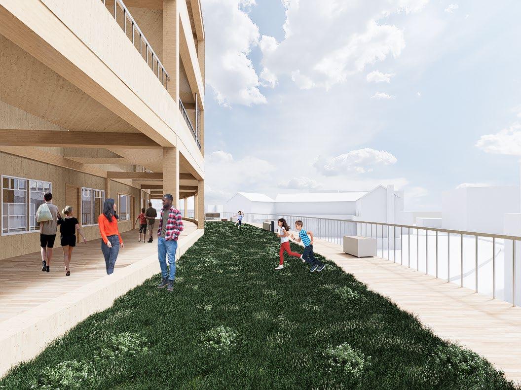
The first floor plan showcases the private affordable housing present in the building ranging from 1 bed affordable flat to 4 bed co living flats. By separating the housing from the mixed use by level, orientation and acess points,this allows the residents to have more privacy.
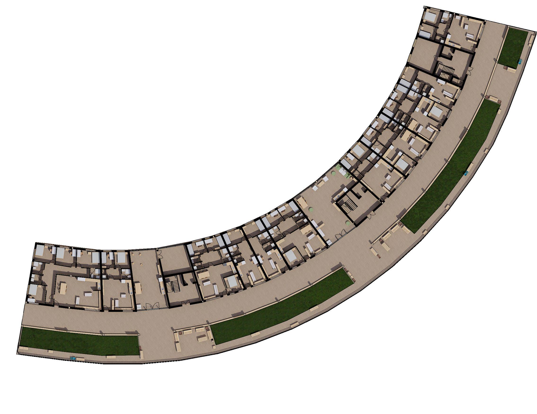
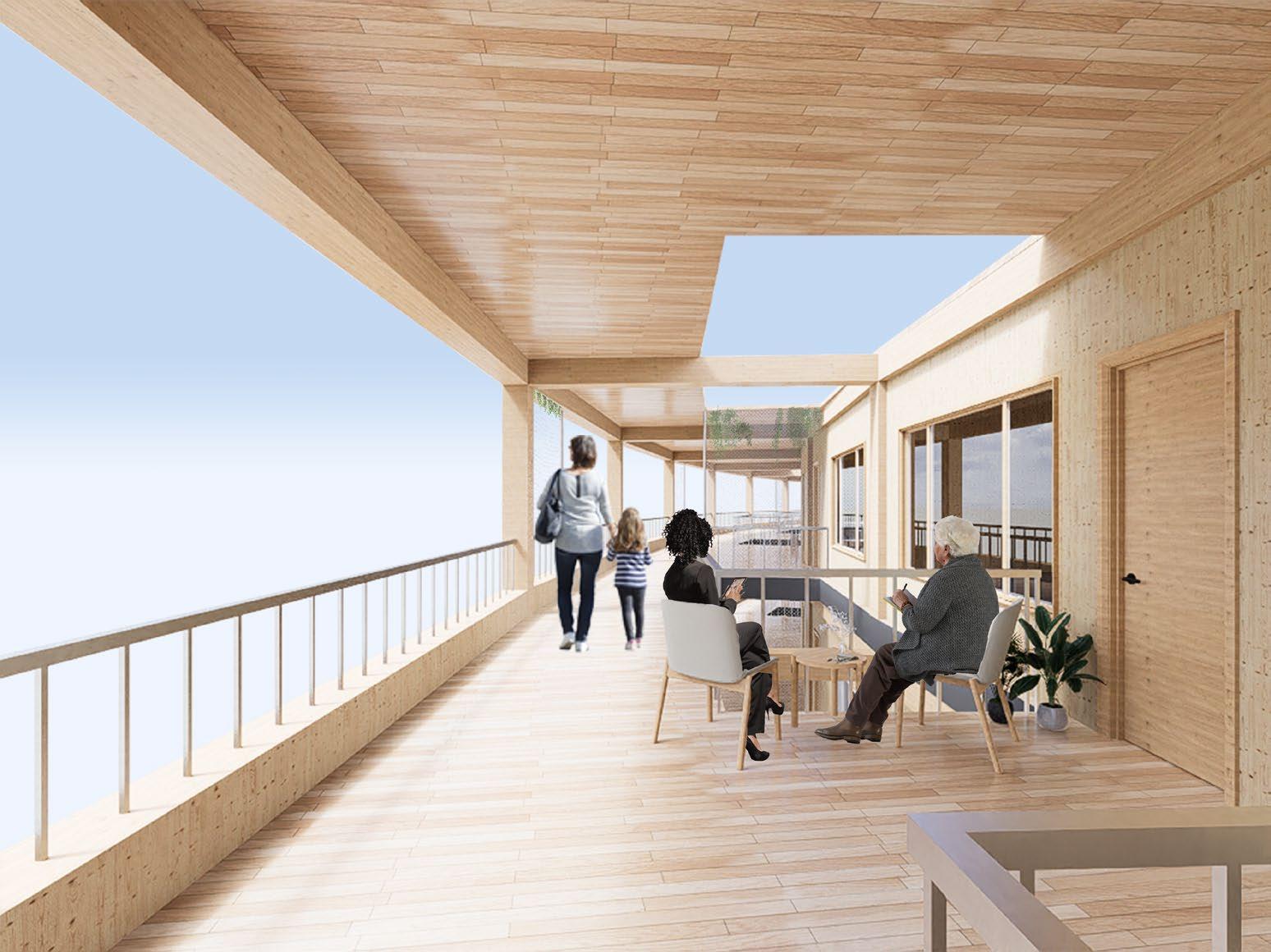
Each flat has access to both communal spaces as well as private residential roof gardens which all can make use of, creating on each floor a connected community.
BA3 - Design Sythensis 18 24 - 4 bed co - living flats 25 - 3 bed affordable flat 26 - 2 bed affordable flat 27 - 1 bed affordable flat 28 - Communal space 29 - Walkway 30 - Residential roof garden 31 - Stairs and elevators 32 - Storage
29 30 31 28 25 27 27 25 31 32 28 26 24 26 25 25 4th Floor - Walkway
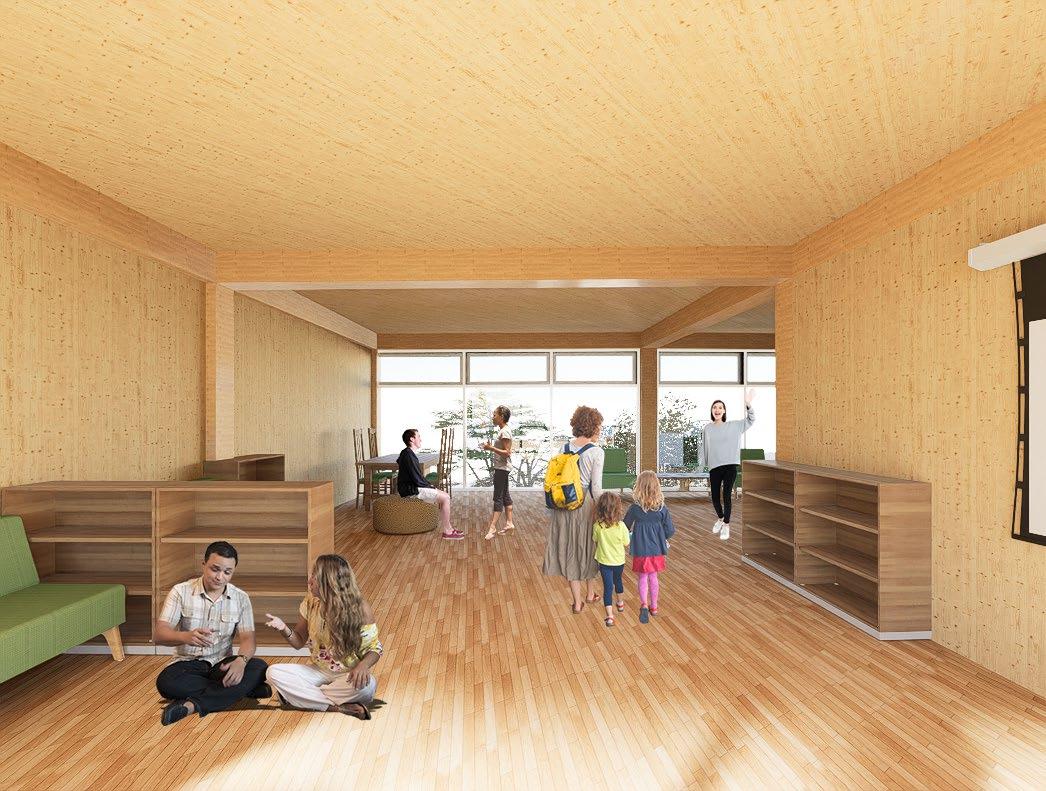
1st floor - Entrance/Communal Area
1st floor - Private Garden/Communal Area
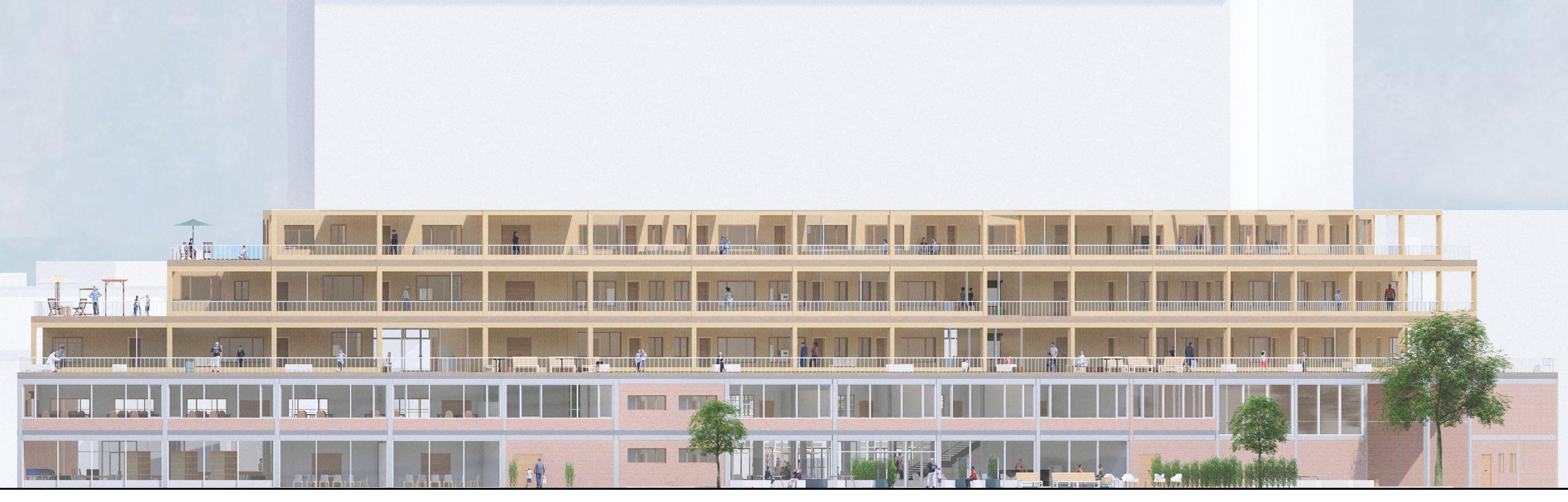
CLT is the main building material used within the residential area, signifying both a change in fuction for the building uses as well as the change in old and new as resused brick of the previous building on the site was used on the ground floor and CLT used for the new residential. 17 Email - jkuforiji76@gmail.com Phone number - 07848874448
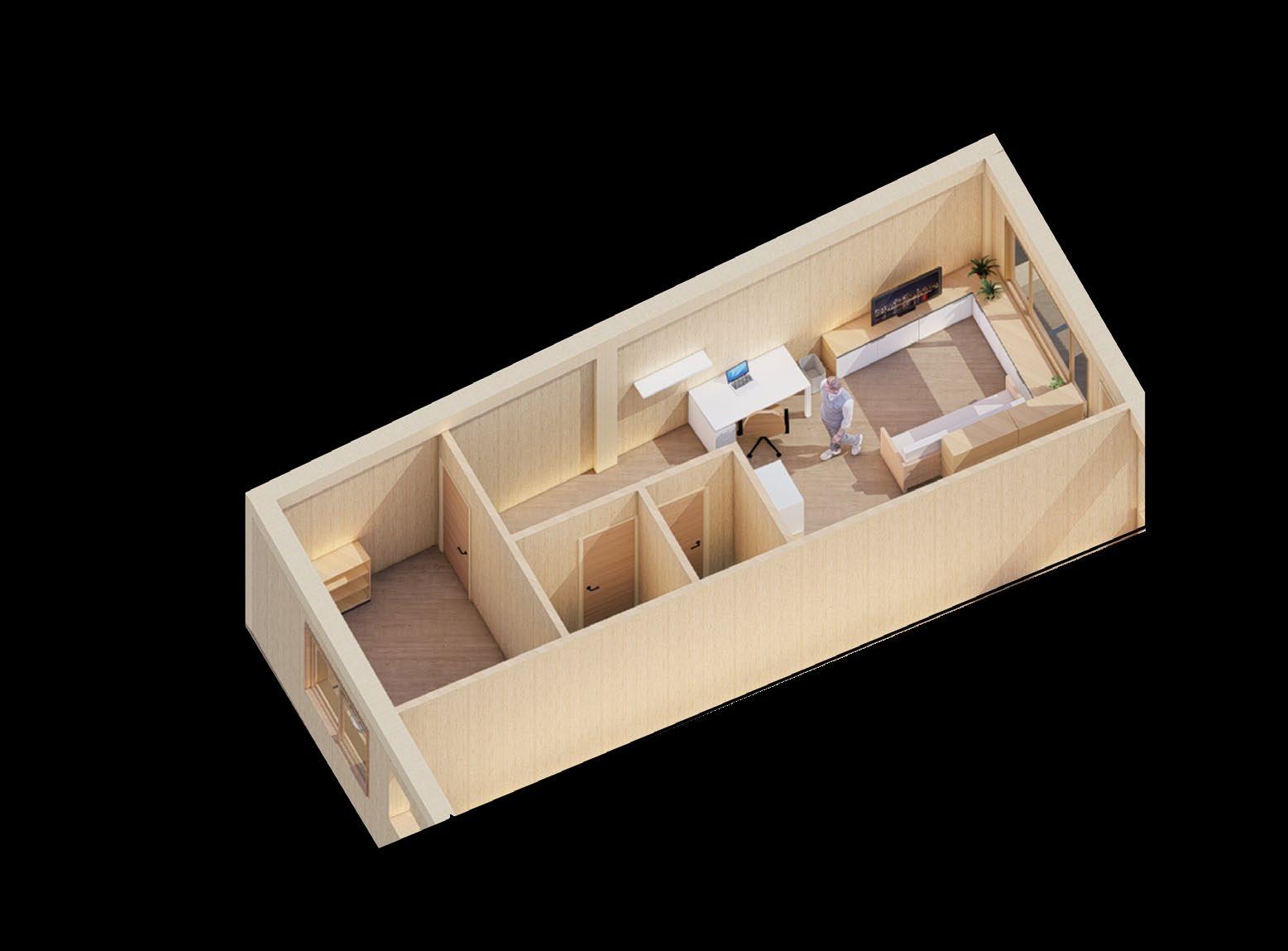
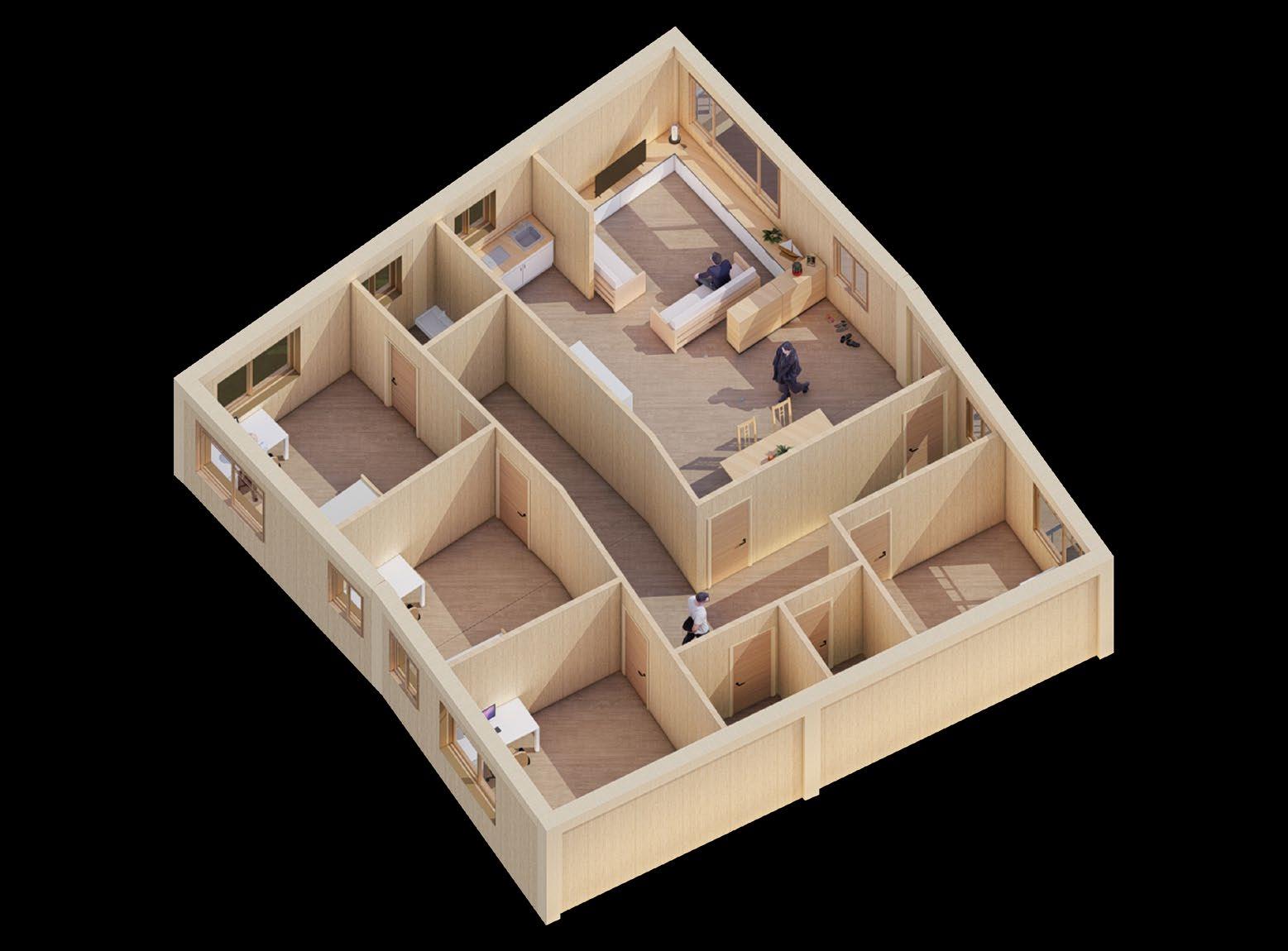
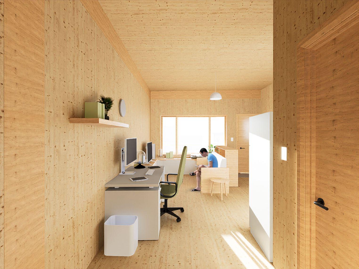
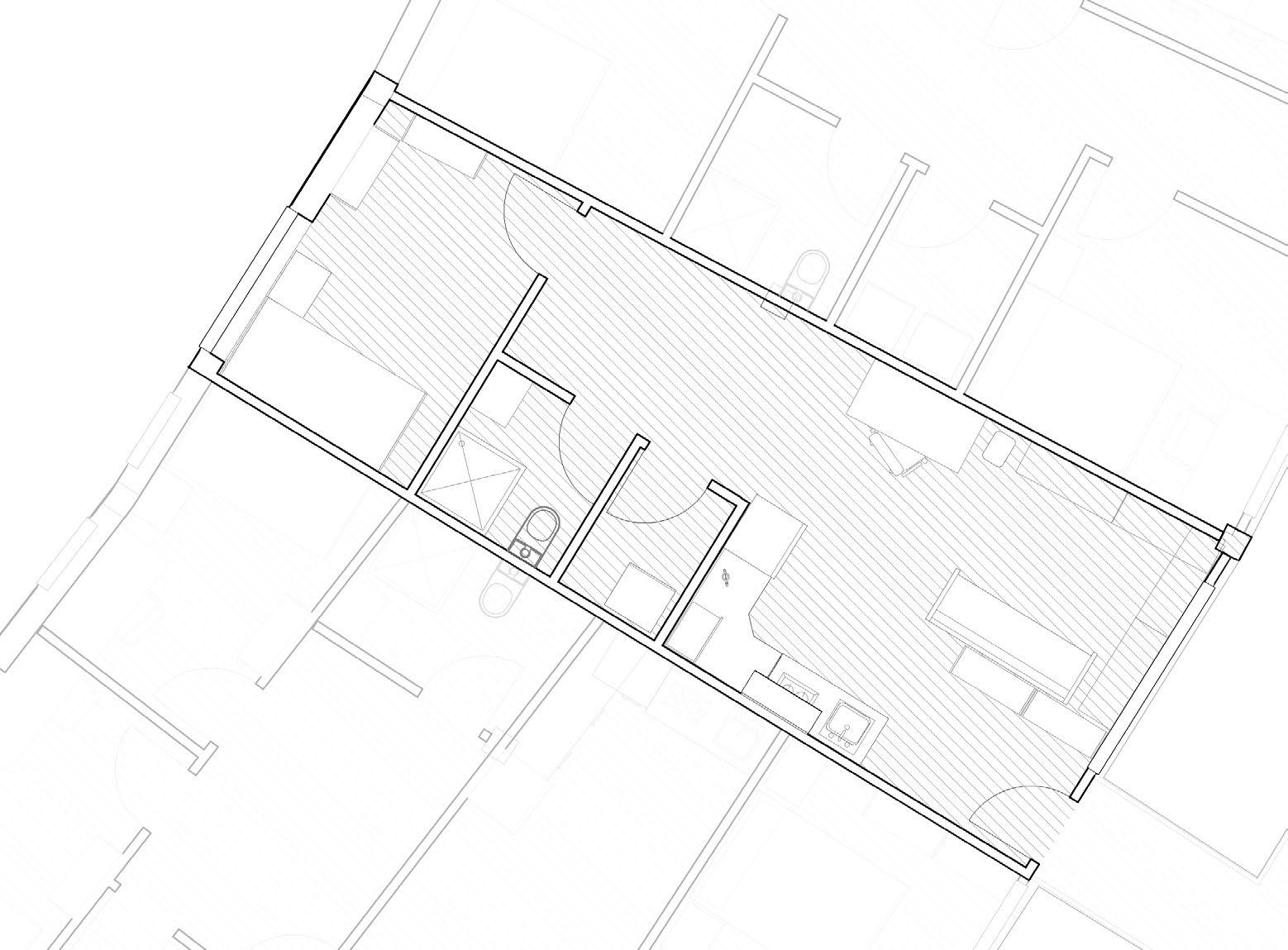

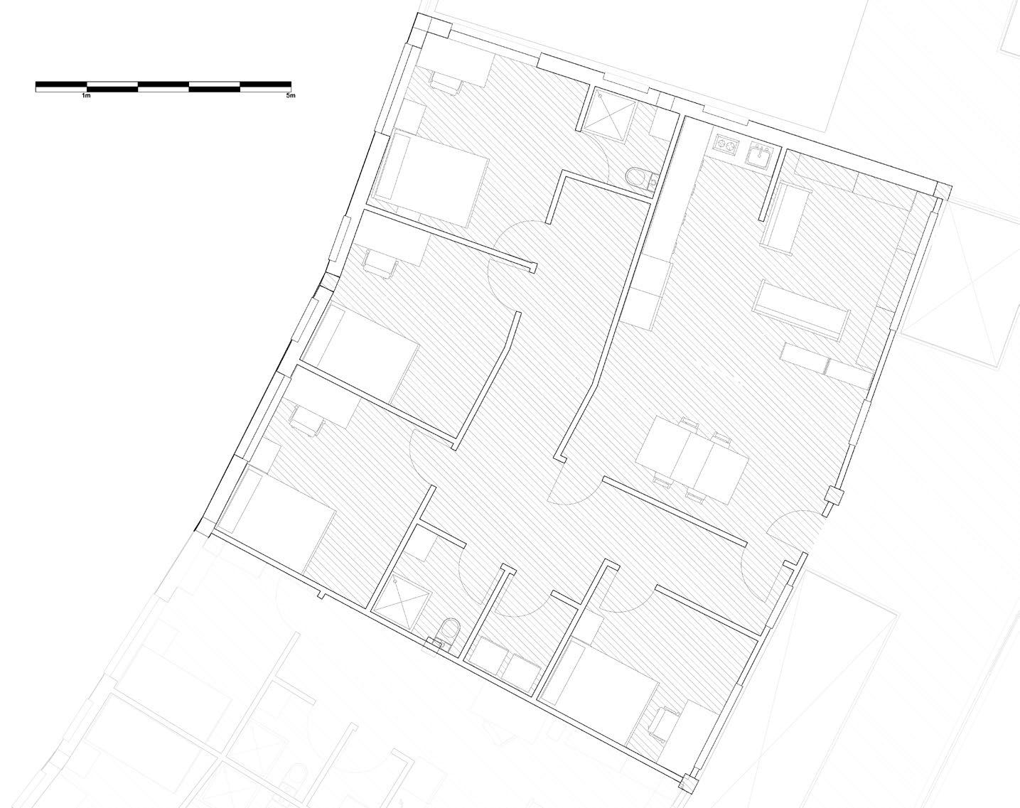
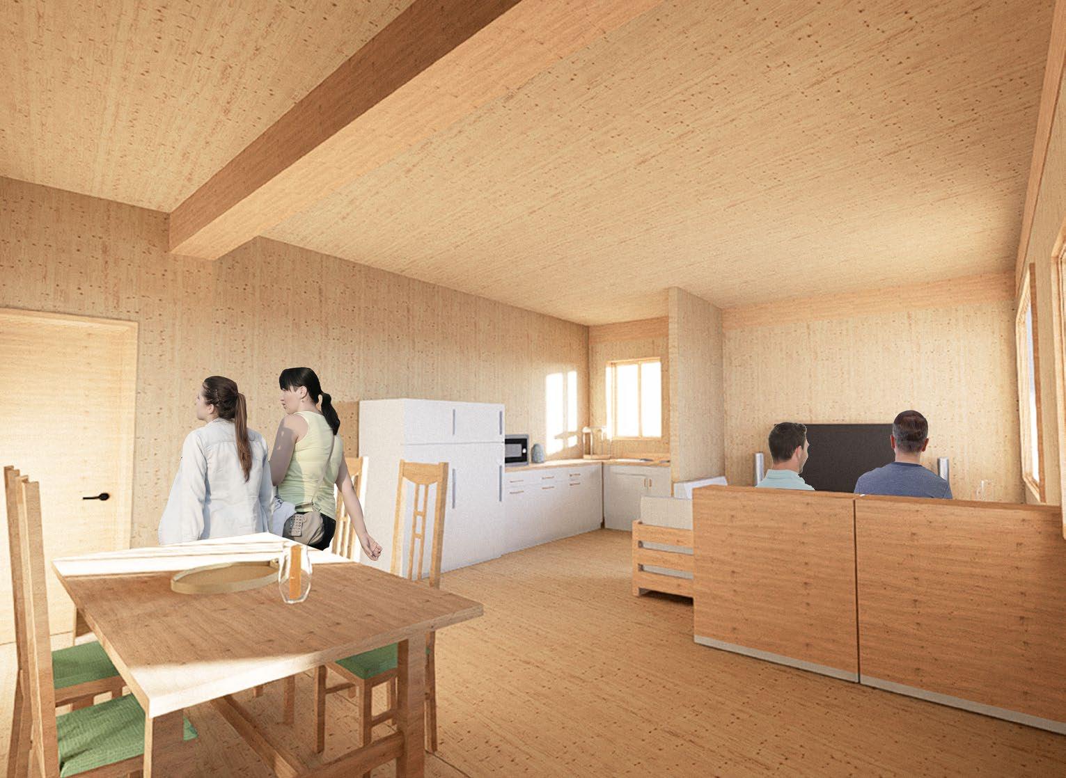
BA3 - Design Sythensis 20 19 1 Bed - Floor Plan 1 Bed - Interior View 1 Bed - Room Axo 4 Bed - Floor Plan 4 Bed - Interior View 4 Bed - Room Axo 1 - Open plan living and dining 2 - Kitchen 3 - Office space 4 - Storage 5 - Bathroom 6 - Bedroom 1 - Open plan living and dining 2 - Kitchen 3 - Storage 4 - Bathroom and Toilets 5 - 2 Bedroom 1 2 3 4 5 6 1 2 3 4 5 4 5 5 5 Email - jkuforiji76@gmail.com Phone number - 07848874448


BA3 - Design Sythensis 22
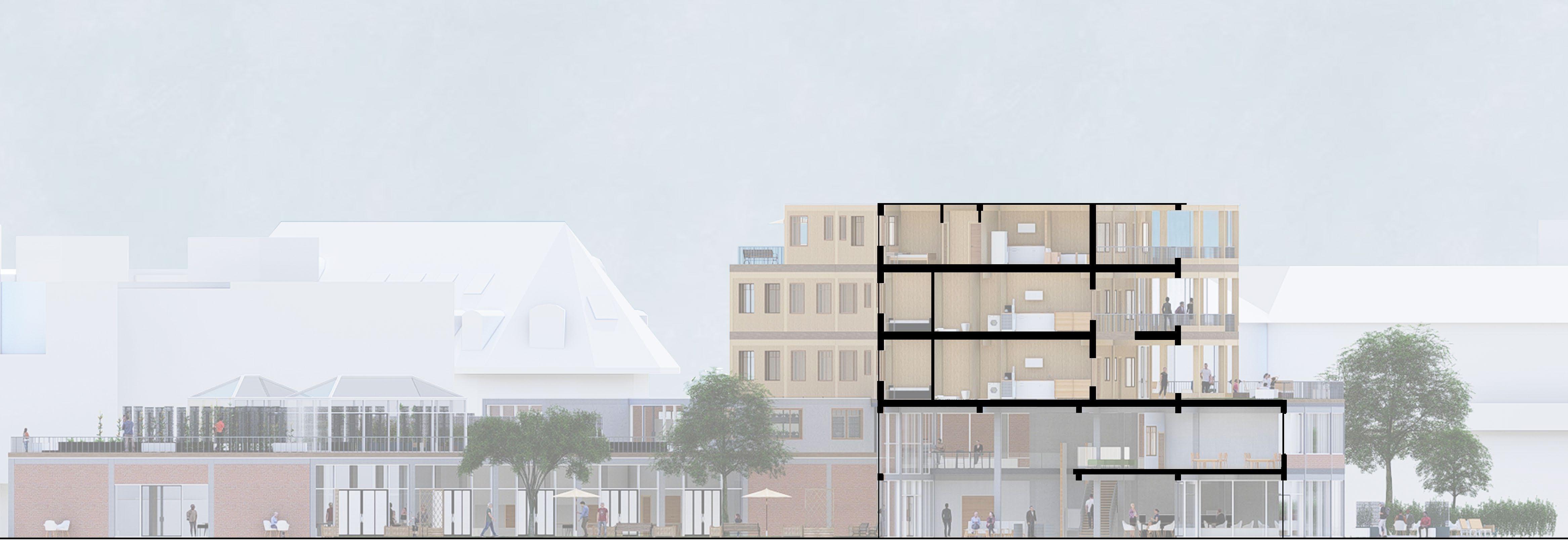
Section BB
21 Email - jkuforiji76@gmail.com Phone number - 07848874448
South Elevation
BA3 - Design Preperation
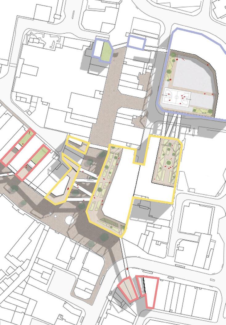
For our 1st project in the 3rd year we were given the task of creating an urban planning scheme which would revitalise the Portsmouth city centre area.
The main focus of my urban planning scheme was ,through analysis, to discover what key features ,which a city centre would have/need, were either missing or underused within the surrounding area and from that anaysis, reincorporate them back into the city centre while bring new sense and purpose to them.
BA3 - Design Preperation 24
23 Email - jkuforiji76@gmail.com Phone number - 07848874448
6 focuses of scheme


In order to figure out which ways to revitalise Commerical road analysis of the site was conducted to understand: what is present,what is missing, what coud be added and what could be improved.
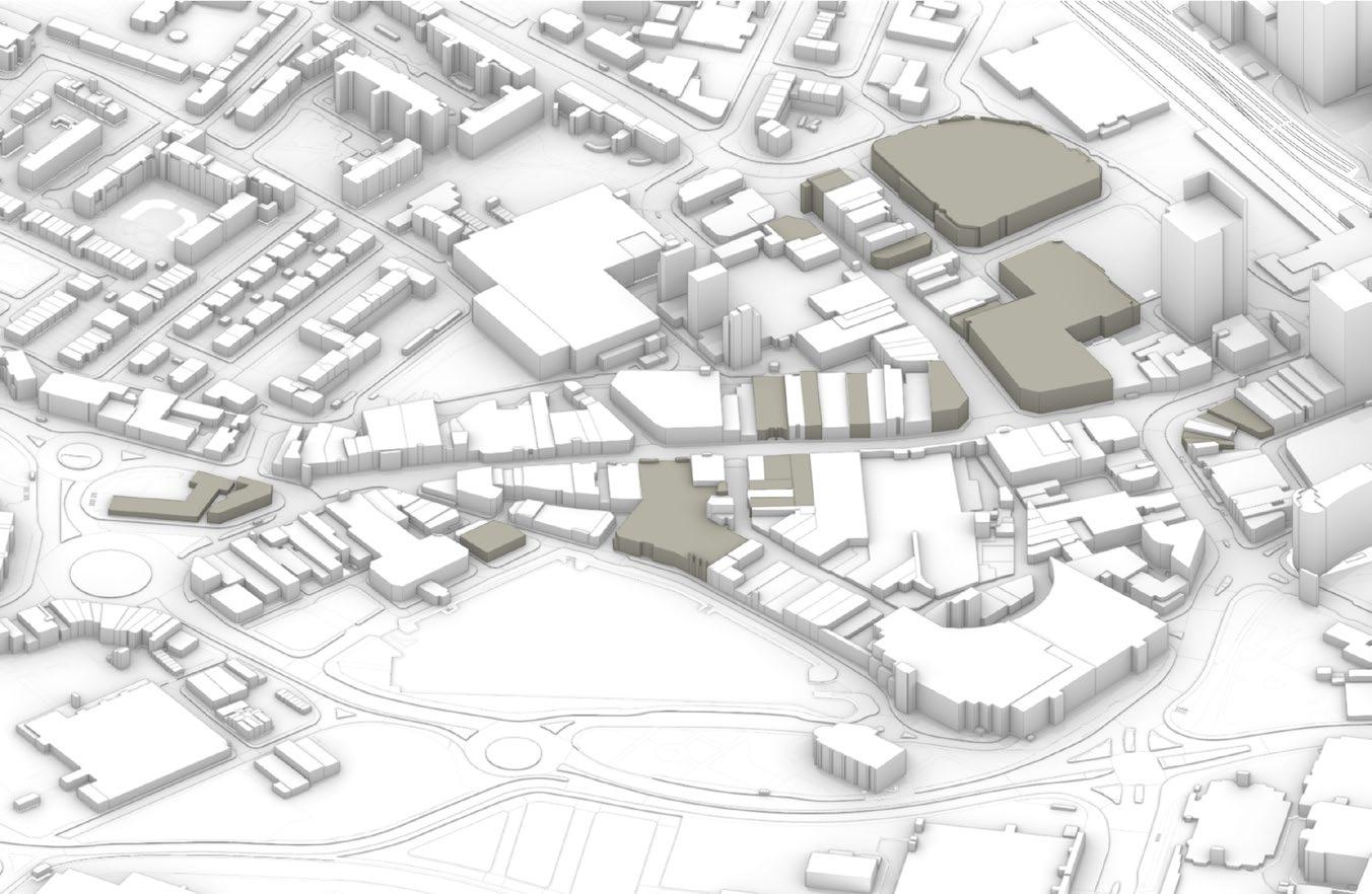
After analysing Commercial road, 6 main points of interest stood out to me as areas in which if focused on could help rejuvinate Commerical Road.
My focuses were on 6 points: Entertainment - VegetationEducation - Farmers Market - Homeless aid - Community.

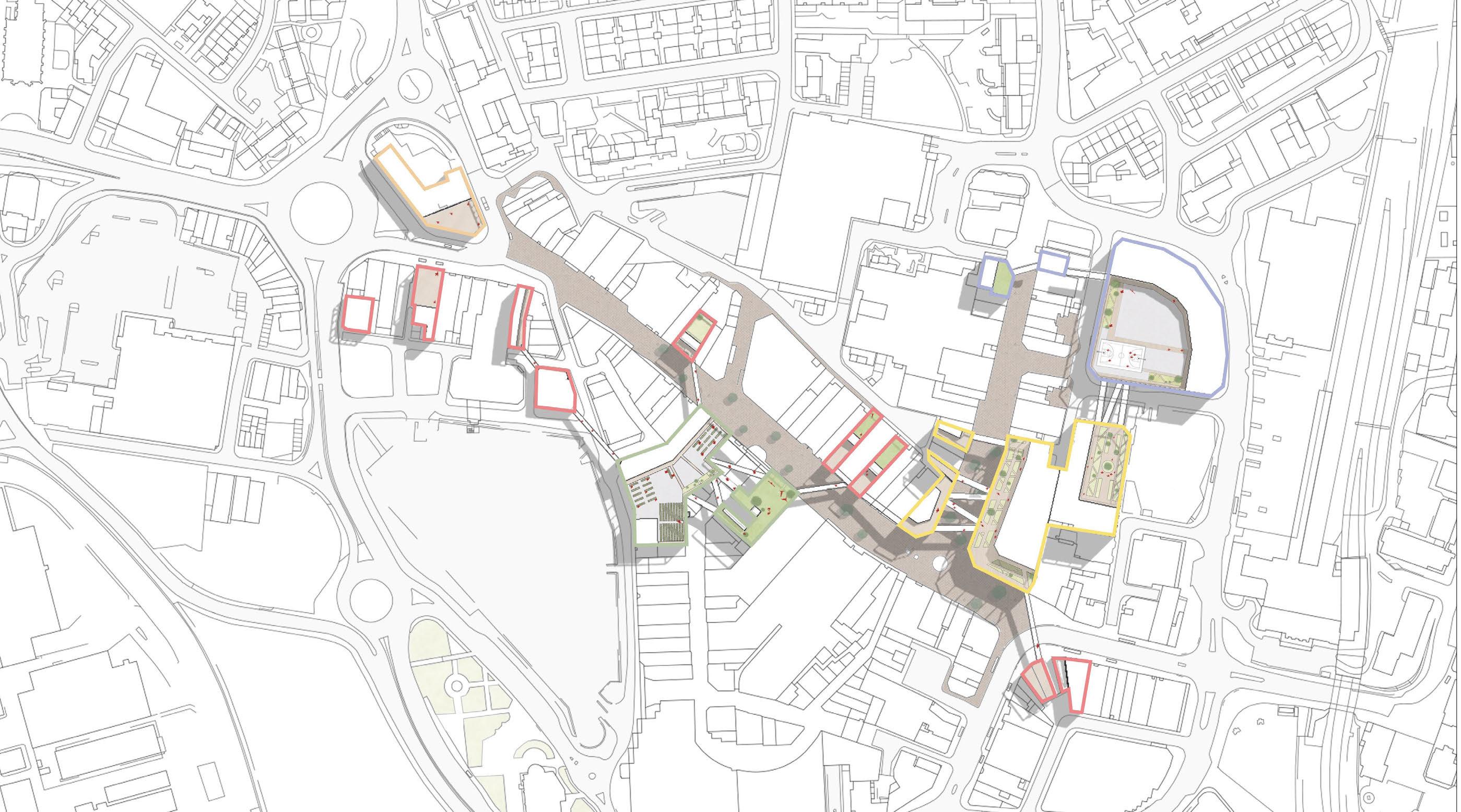
From investigation, realised located around the site are many nnused buildings sorrounding the site. Keeping with the theme of rejuvinating commerical road, reusing these unused buildings and linking them with the 6 key focuses gained from analysis became a key focus on the scheme.
BA3 - Design Preperation
Community Education Entertainment Farmers Market Homeless aid Vegetation
25 26
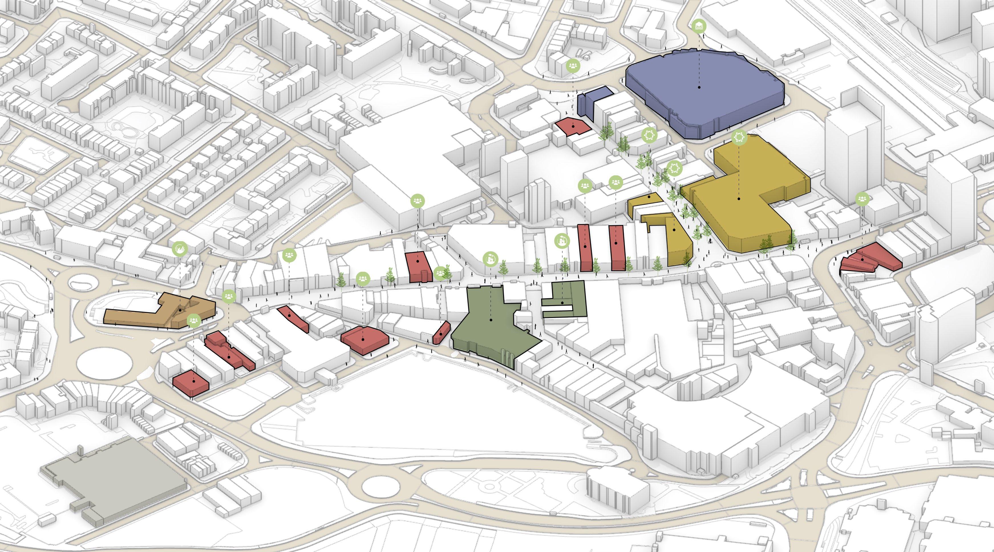
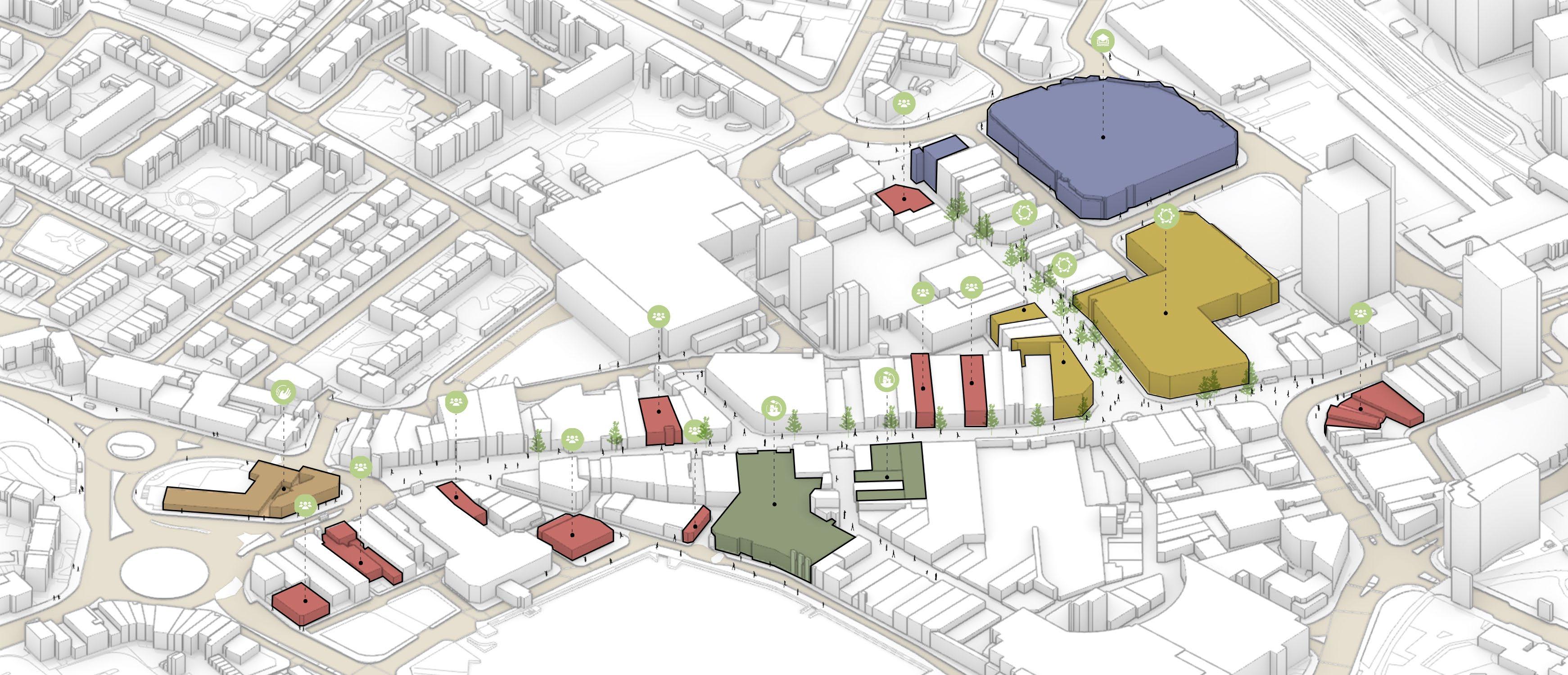
Community Hub Education Hub Farmers Market Hub Homeless aid Hub Entertainment Hubs Vegetation Unused Buildings
Email - jkuforiji76@gmail.com Phone number - 07848874448
The finialised urban concept saw new life brought to Commerical Road by making use of the unused buildings surrounding the site.
Each unsued building now served a new use, linking to the 6 main focuses that were missing or underused within the area.
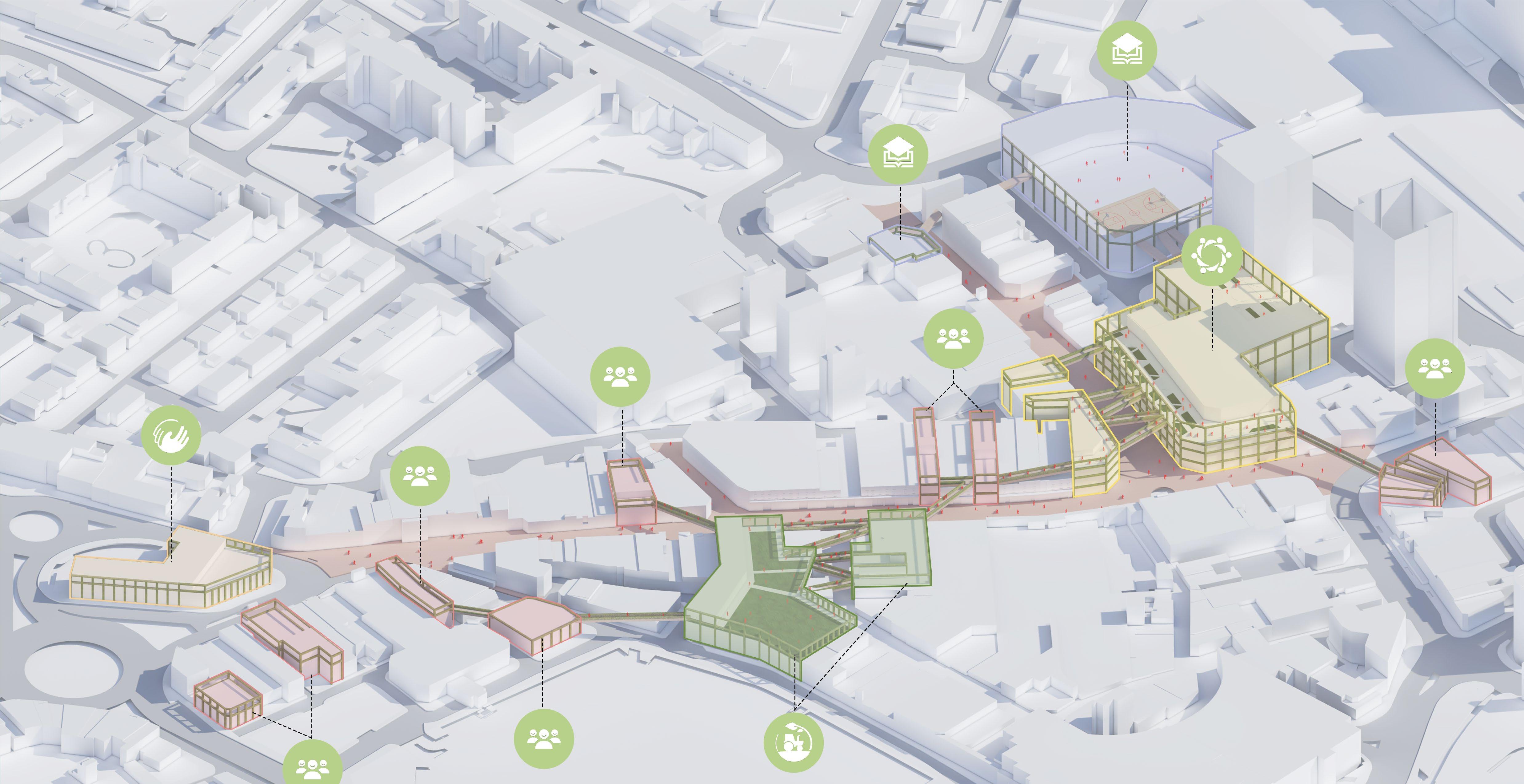
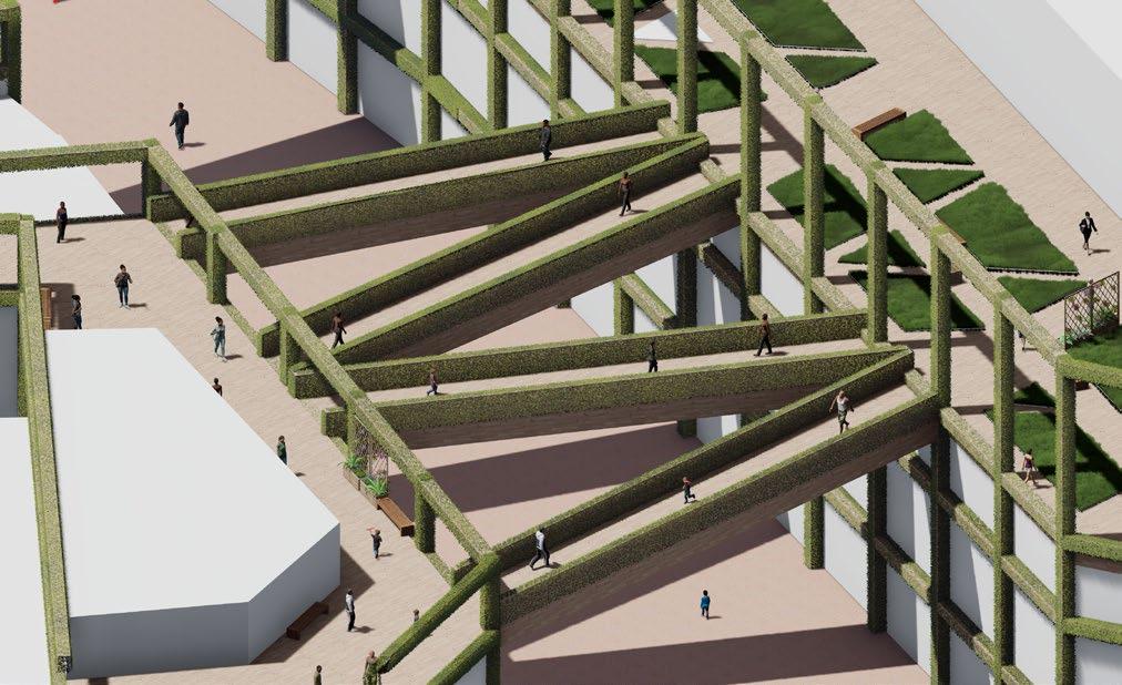
Each rejuvenate building were then connected to one anther via sky walkways which would allow for easy passage from one building to another.
Each rejuvinated building were also structrally suported with exterior cross laminated timer which, while acting as an exterior facade can also act as structural support if the buildings were to be expanded.
BA3 - Design Preperation
Proposed Site Axonometric
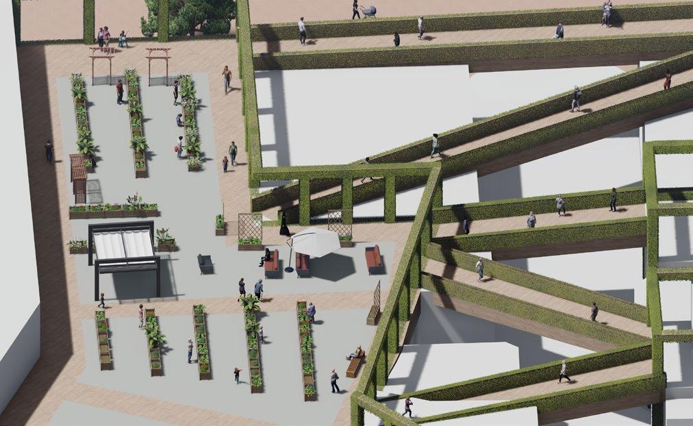
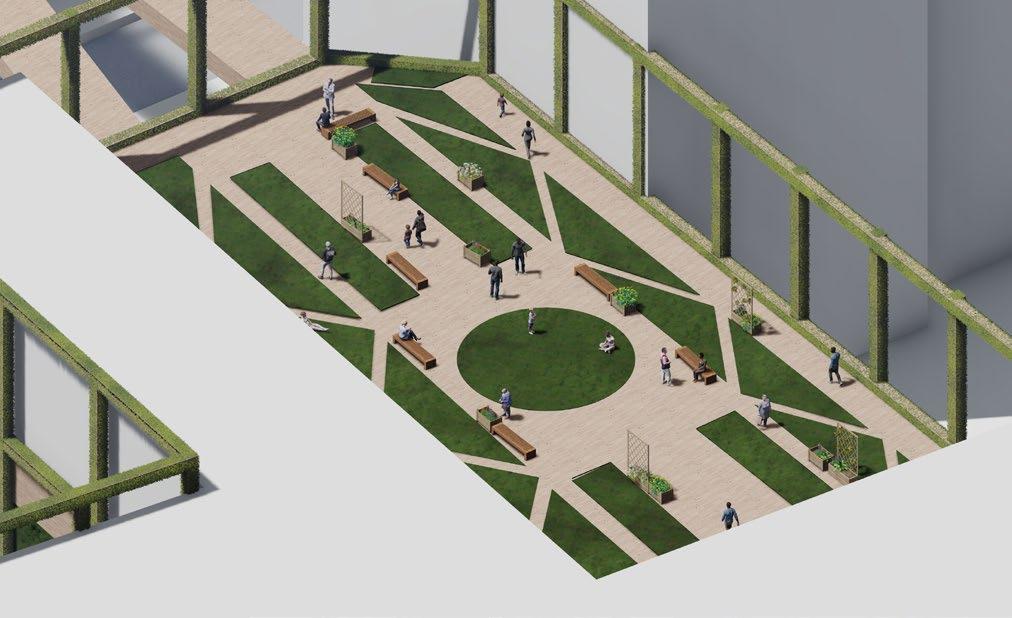
Communal Hub - Roof garden, connecting to educational hub
Communal Hub - Walkways
Farmers Market Hub - Urban farm & linked walkways
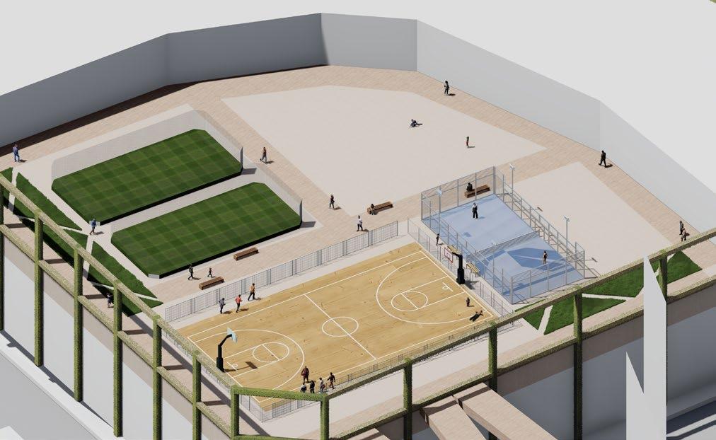
Education Hub - Roof sports area
Community Hub
Education Hub
Farmers Market Hub
Homeless aid Hub
Entertainment Hubs
Vegetation
27 28 Email - jkuforiji76@gmail.com Phone number - 07848874448
BA1 - Pottery Studio
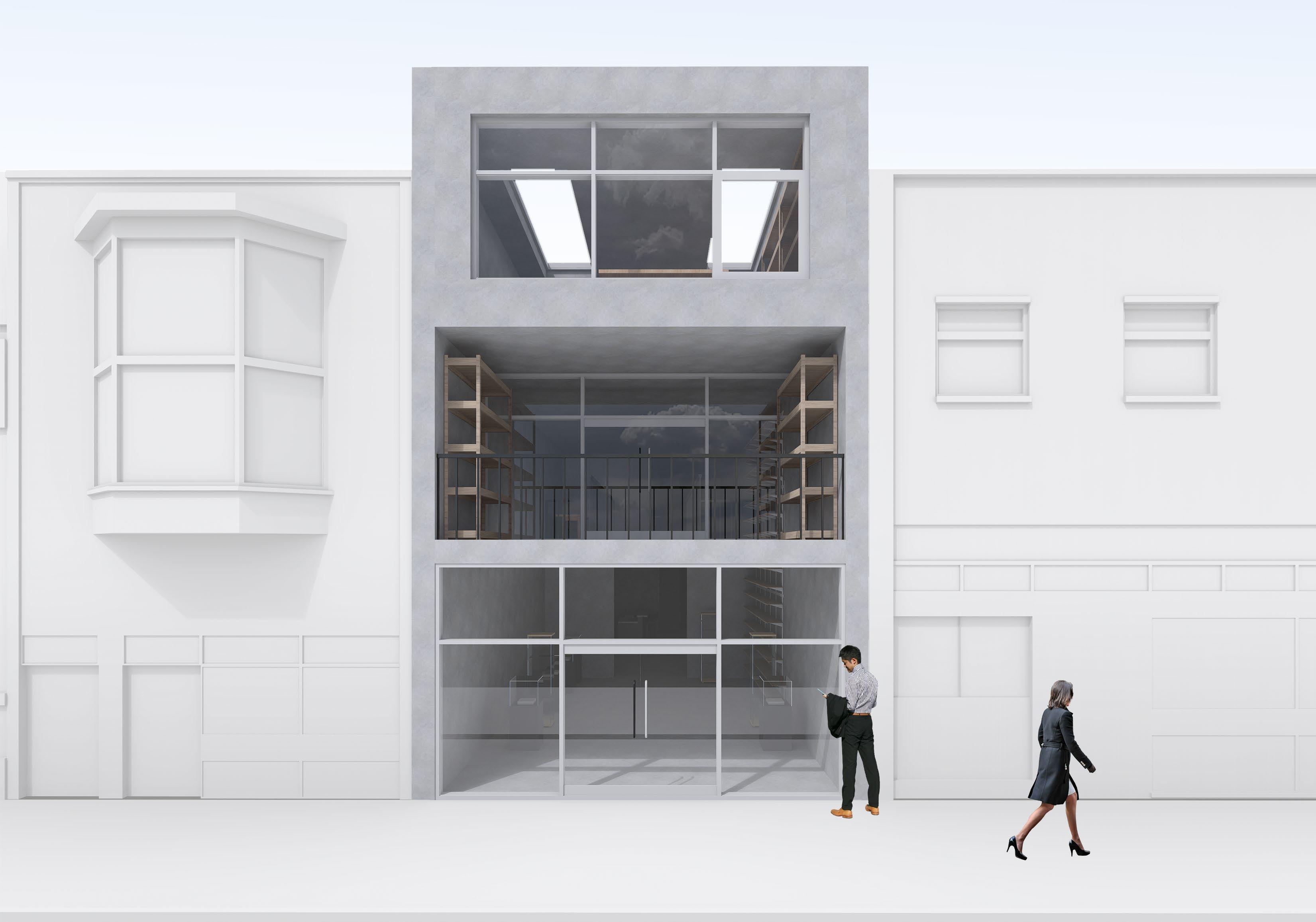
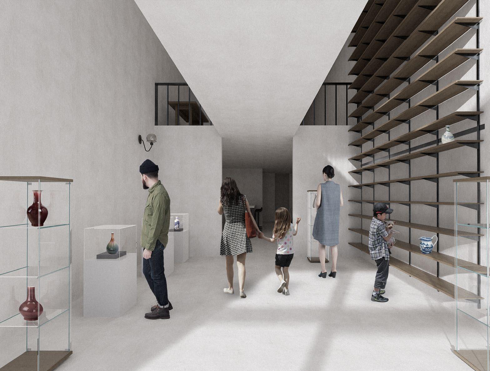
The design sensibility was to create an building which would both act as a blank canvas for the ceramists to have freedom to create within and also showcase their final creations without distractions.
BA1 - Pottery Studio 30
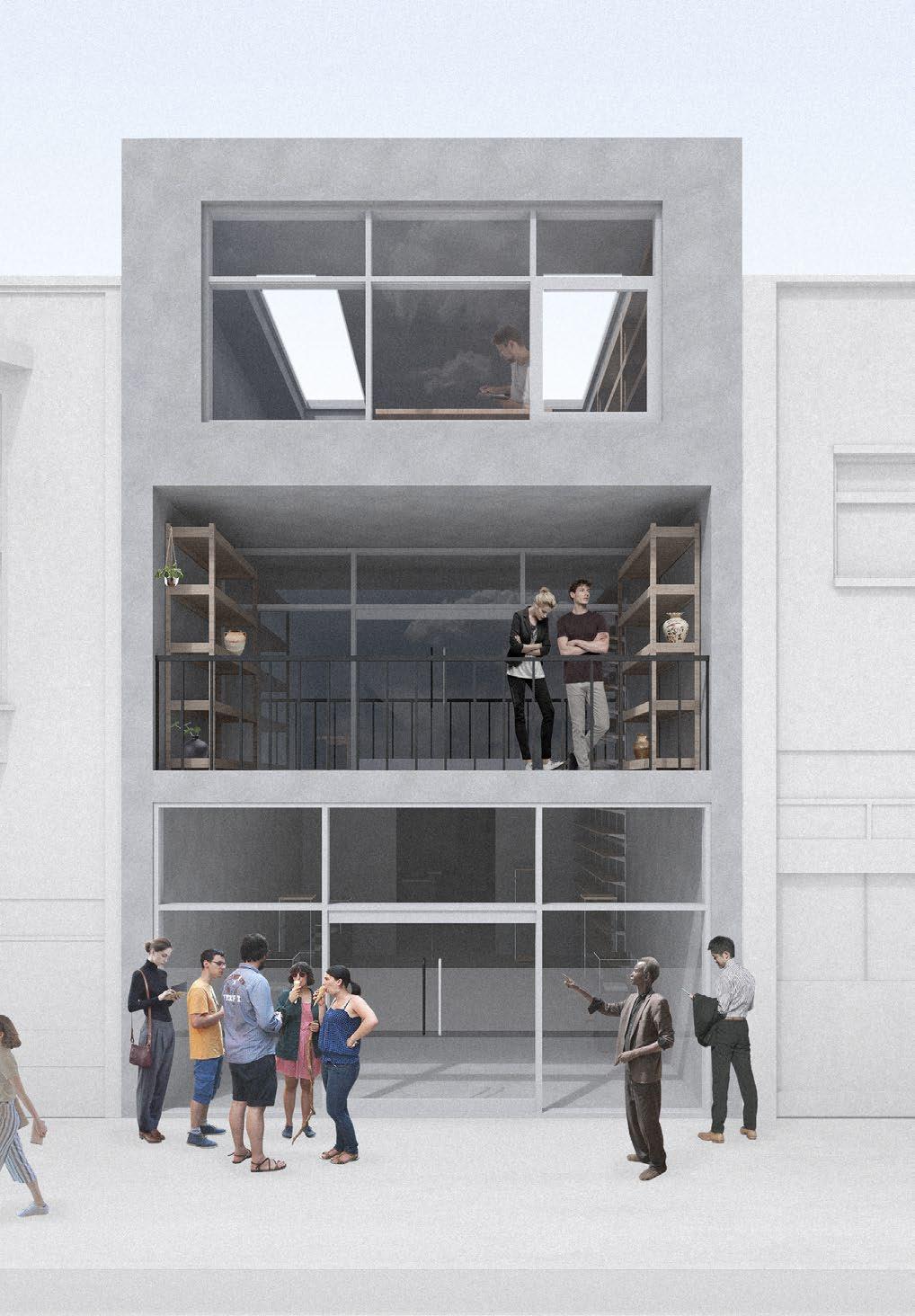
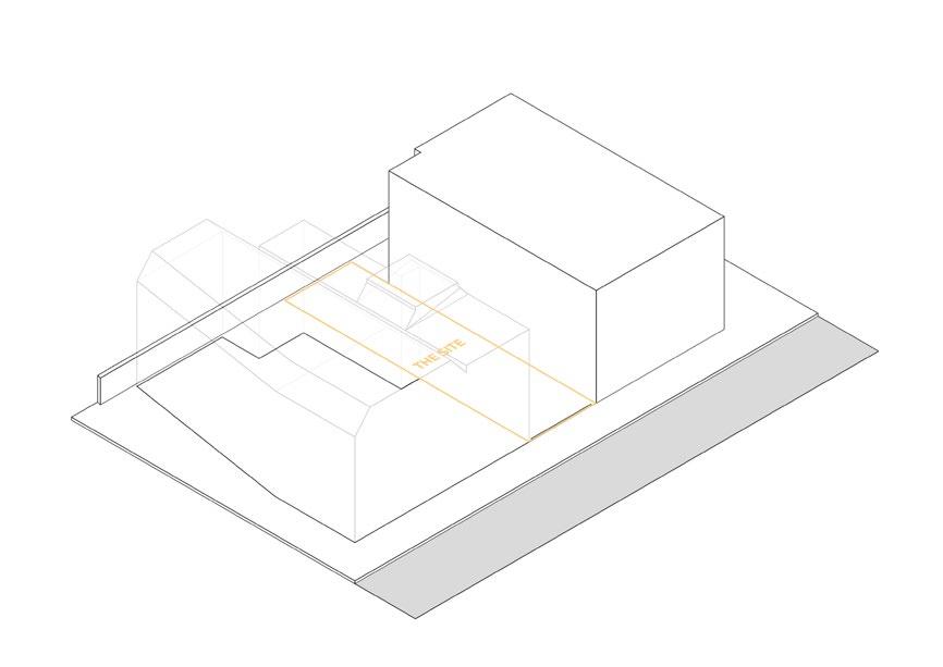
Located in the heart of Albert Road a bustling road in Portsmouth known for it’s creative culture. The concept for the project was to design an Pottery studio/Workshop where ceramists in the local area could create and display their works for the public to admire.
29 Email - jkuforiji76@gmail.com Phone number - 07848874448
BA1 - Pottery Studio 32
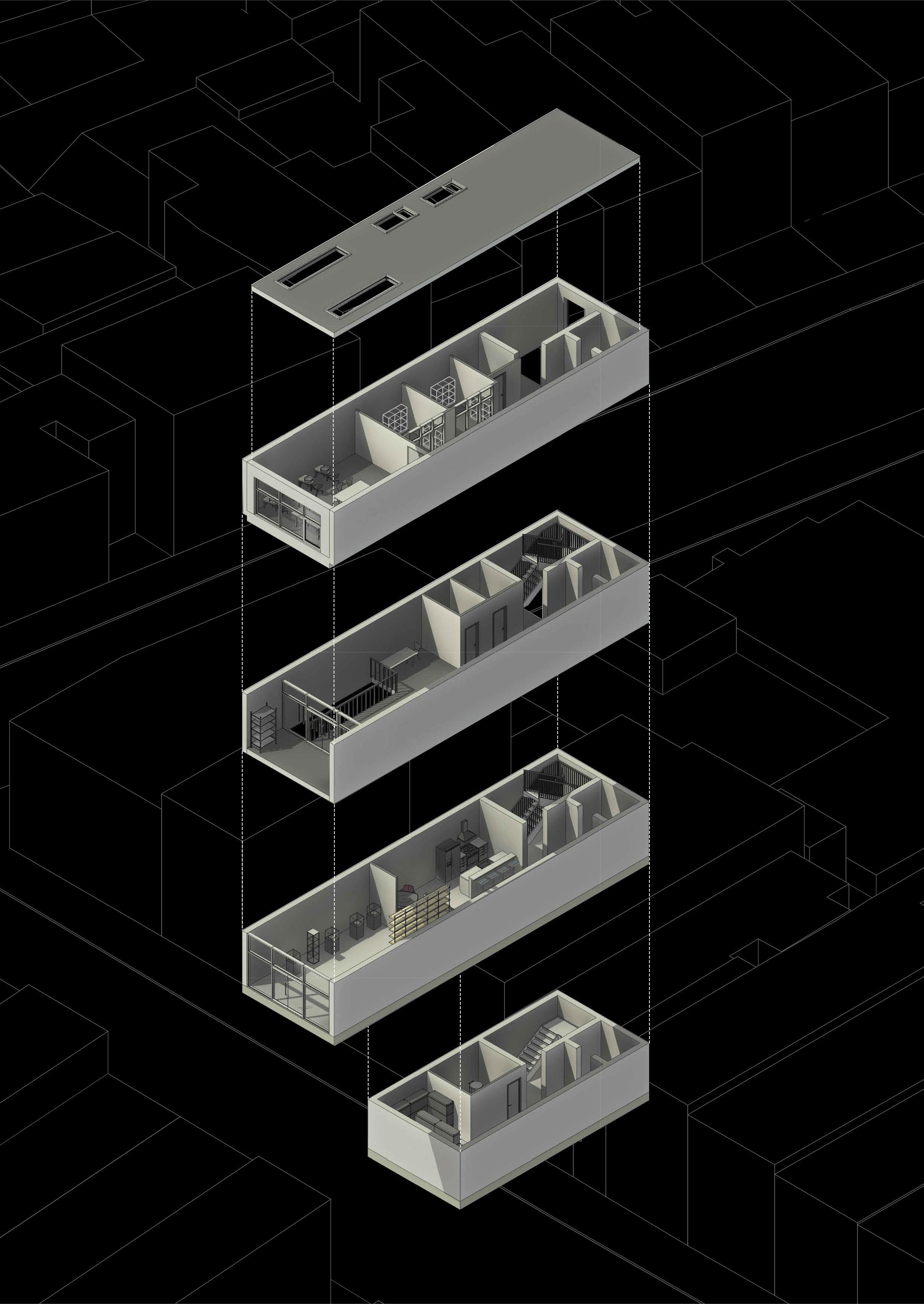
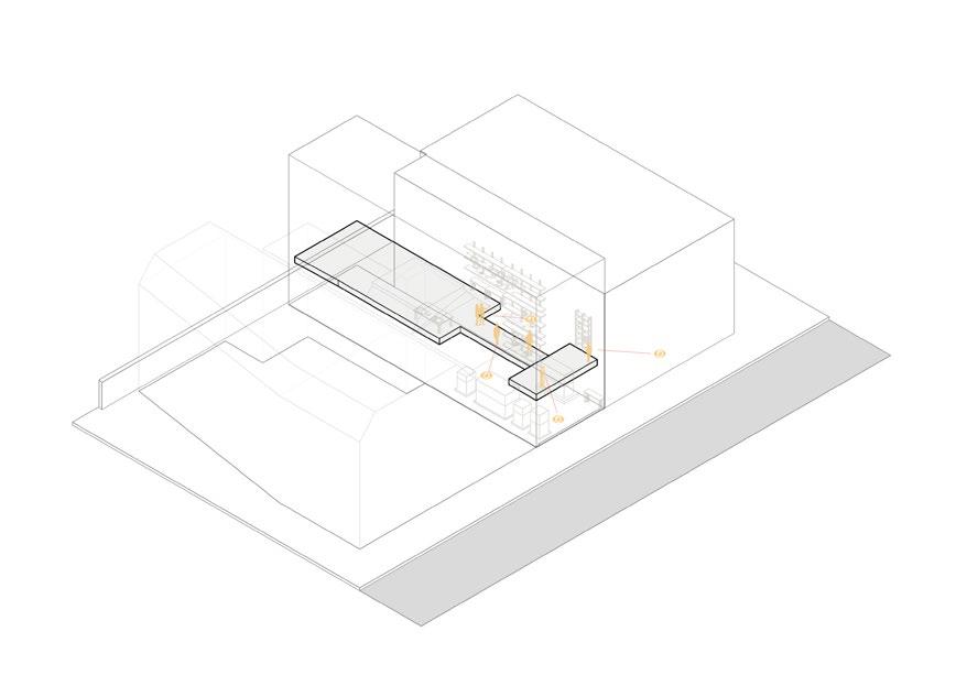
Exploded Axo
1. The site is located between 2 exisiting buildings which see frequent use by those in the local area.
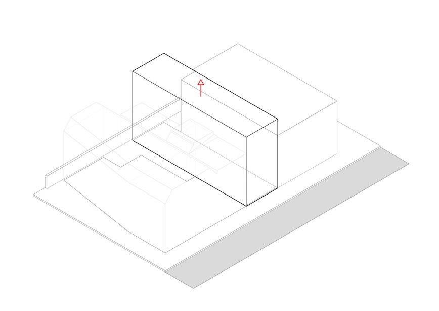
2. The overall mass is extended upwards
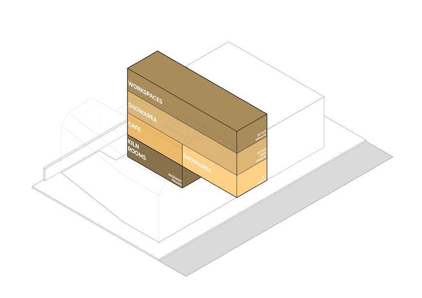
3. The uses of the building were positioned as to allow the uses to shift from public to private as you go up the building, with the most private area being set further below in the basement due to its use.
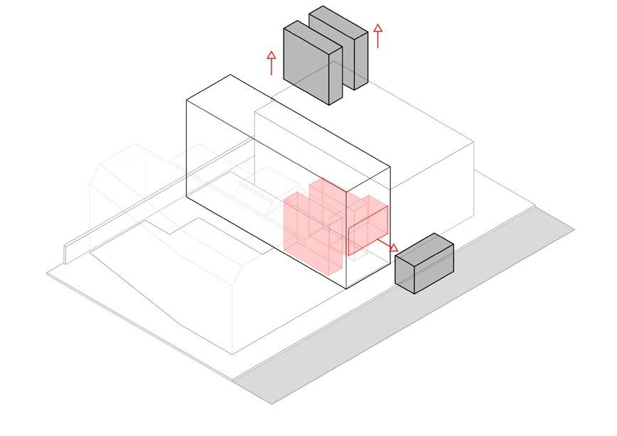
4. Voids were created within the building allowing for new areas for artwork to be showcased open for all to see indepent of your current postioning wihtin the building.
31 Email - jkuforiji76@gmail.com Phone number - 07848874448
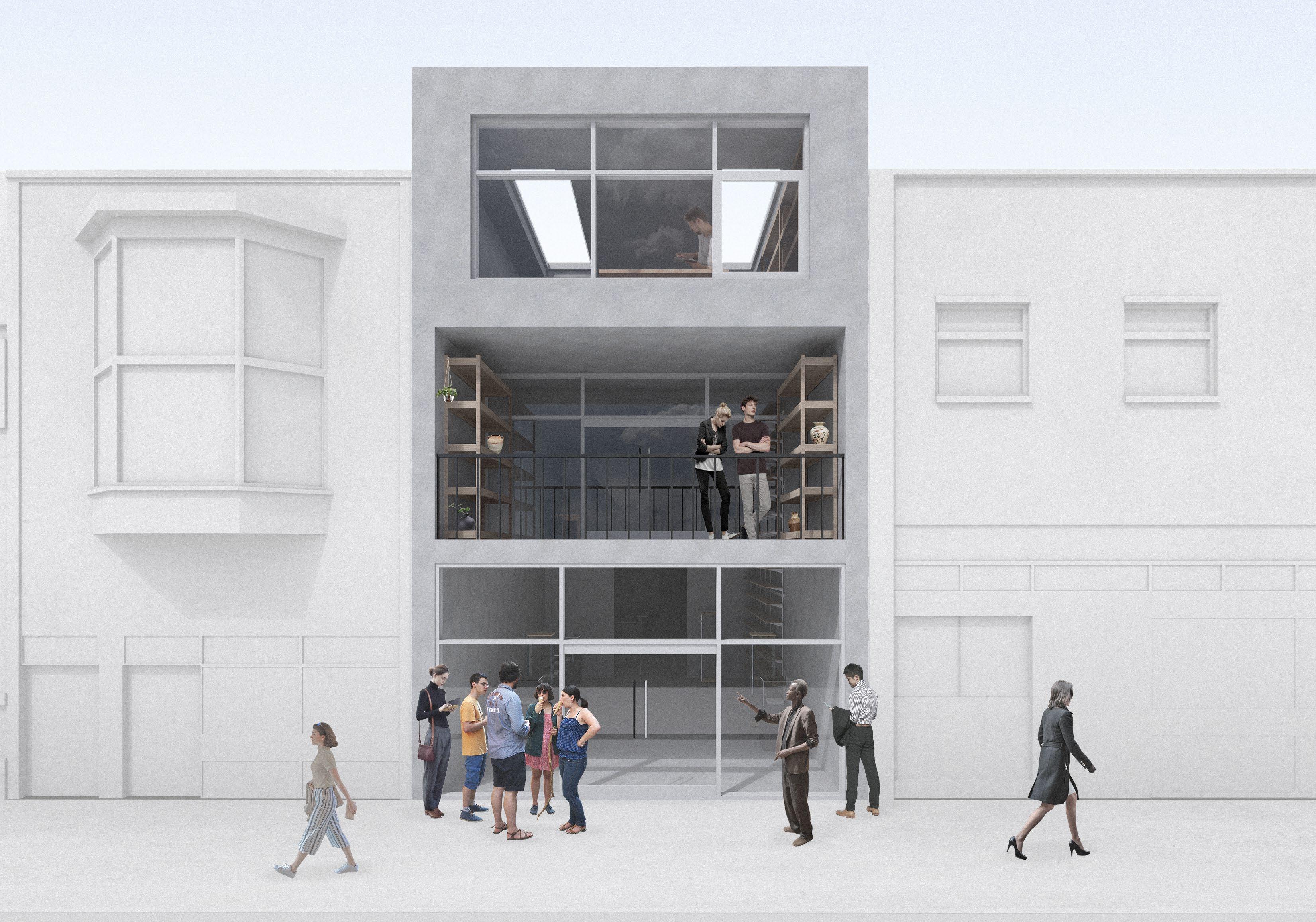
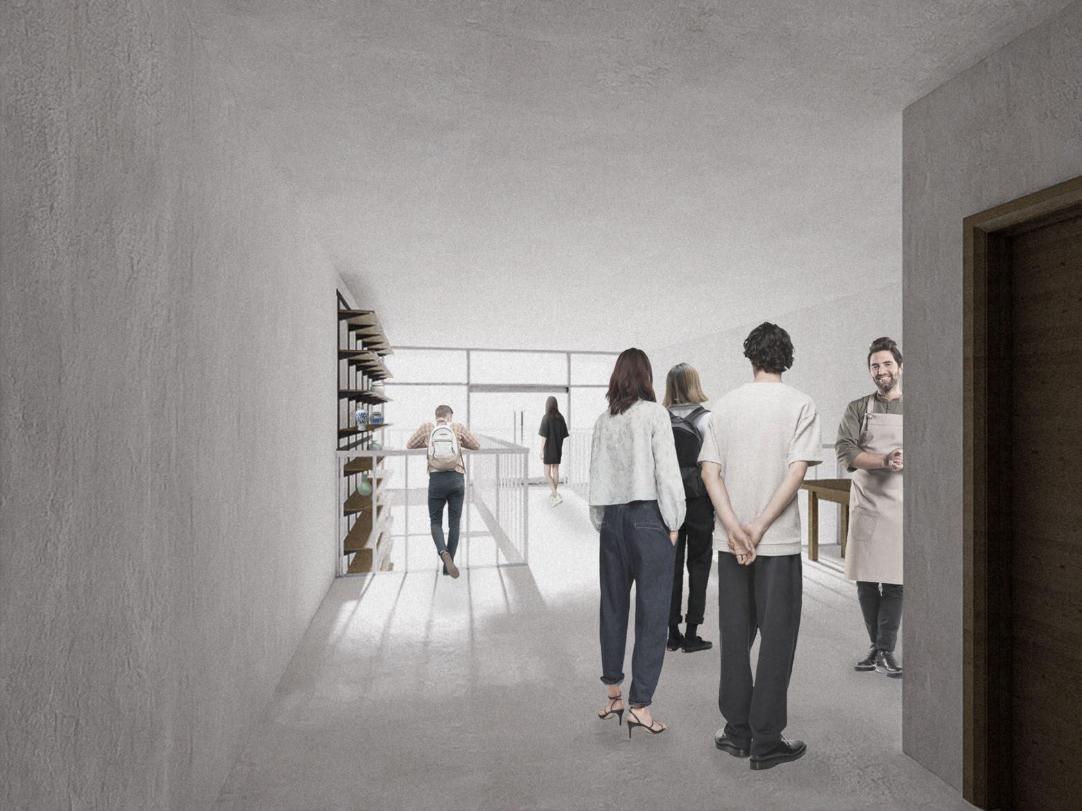
5. With the views both wihtin and outside the building the building becomes more open and connected to the adjacent street, inviting those along to admire the works created.
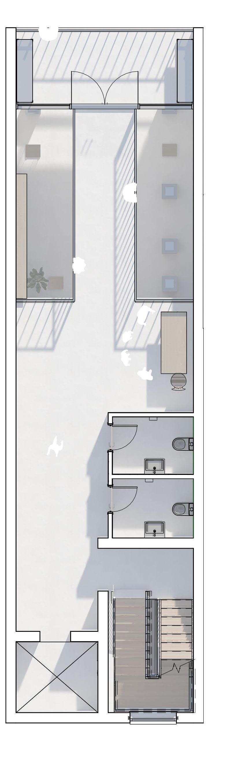
Ground
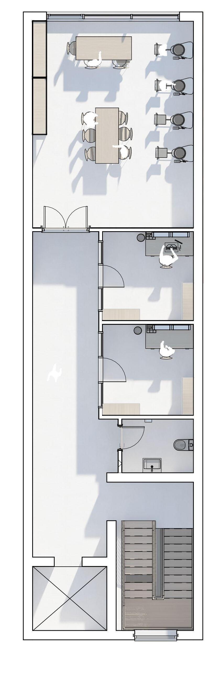
As you enter the building you are greeted to the showroom where the art works created by the ceramists are showcased, located also on the ground floor is a cafe where you can socialise with both the artists and locals in the area.
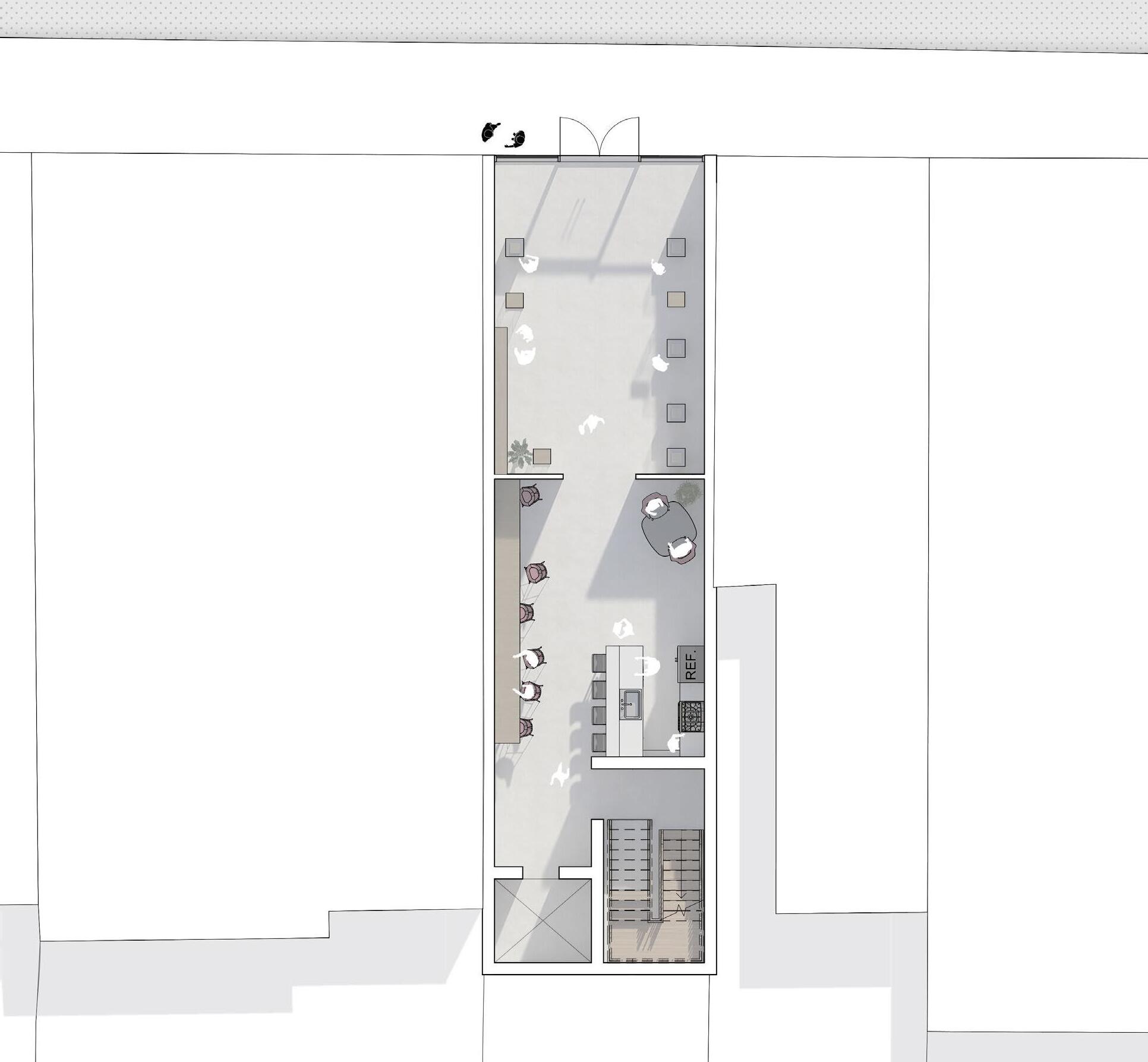
The first floor serves as a testing/showcase area while having connections to the balconey. Ceramists can teach lessons to those who are intrested while others can view the artworks along the walls and also below from the voids alongside the walk way leading to the balconey those on the balconey can have views to Albert Road, connecting to the passeres by.
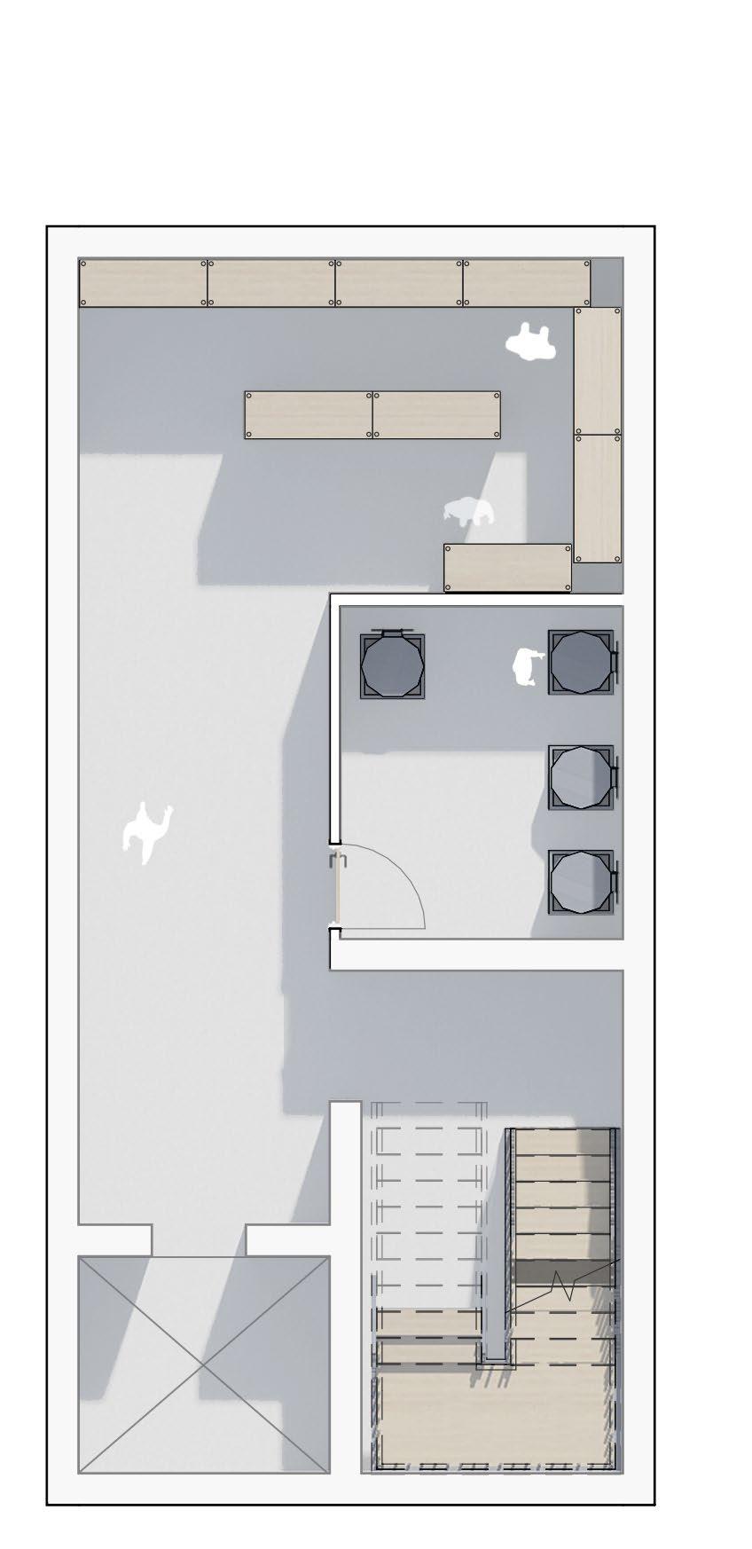
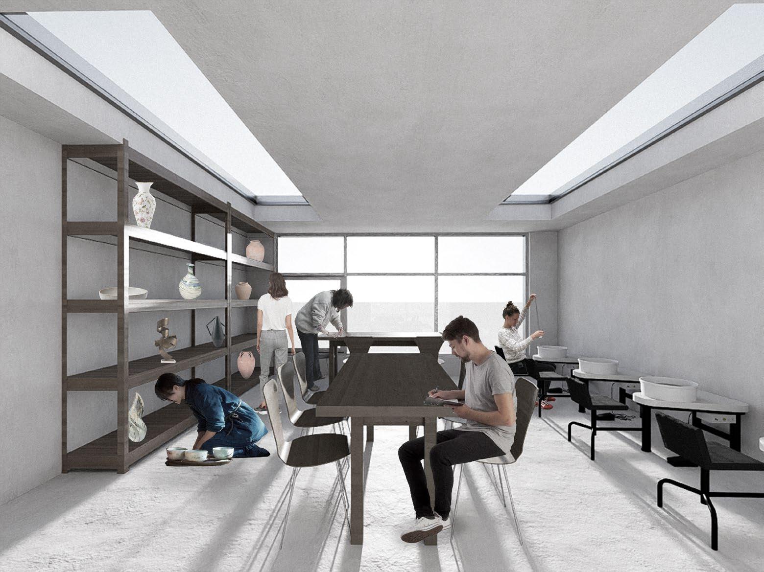
The secound floor fully serves the ceramists, with workspaces and cerative studios where they can create.
BA1 - Pottery Studio 34 1 2 3 1 2 3 3 4 1 2 2 3 4
1 - Showroom 2 - Cafe 3 - Stairs/elevator
floor plan
1 - Balcony
2 - Testing/Showcase Area
3 - Toilets
4 - Stairs/Elevator
1 - Workshop
2 - Creative Studios
3 - Toilets
4 - Stairs/Elevator
1st floor plan
2nd floor plan
1 - Storage room
2 - Kiln room
3 - Stairs/Elevator
1 2 3 33 Email - jkuforiji76@gmail.com Phone number - 07848874448
Basement floor plan
BA1 - Pottery Studio 36
2nd Floor - Workshop
GF floor - Showroom
1st floor - Testing Showcase Area
35 Email - jkuforiji76@gmail.com Phone number - 07848874448
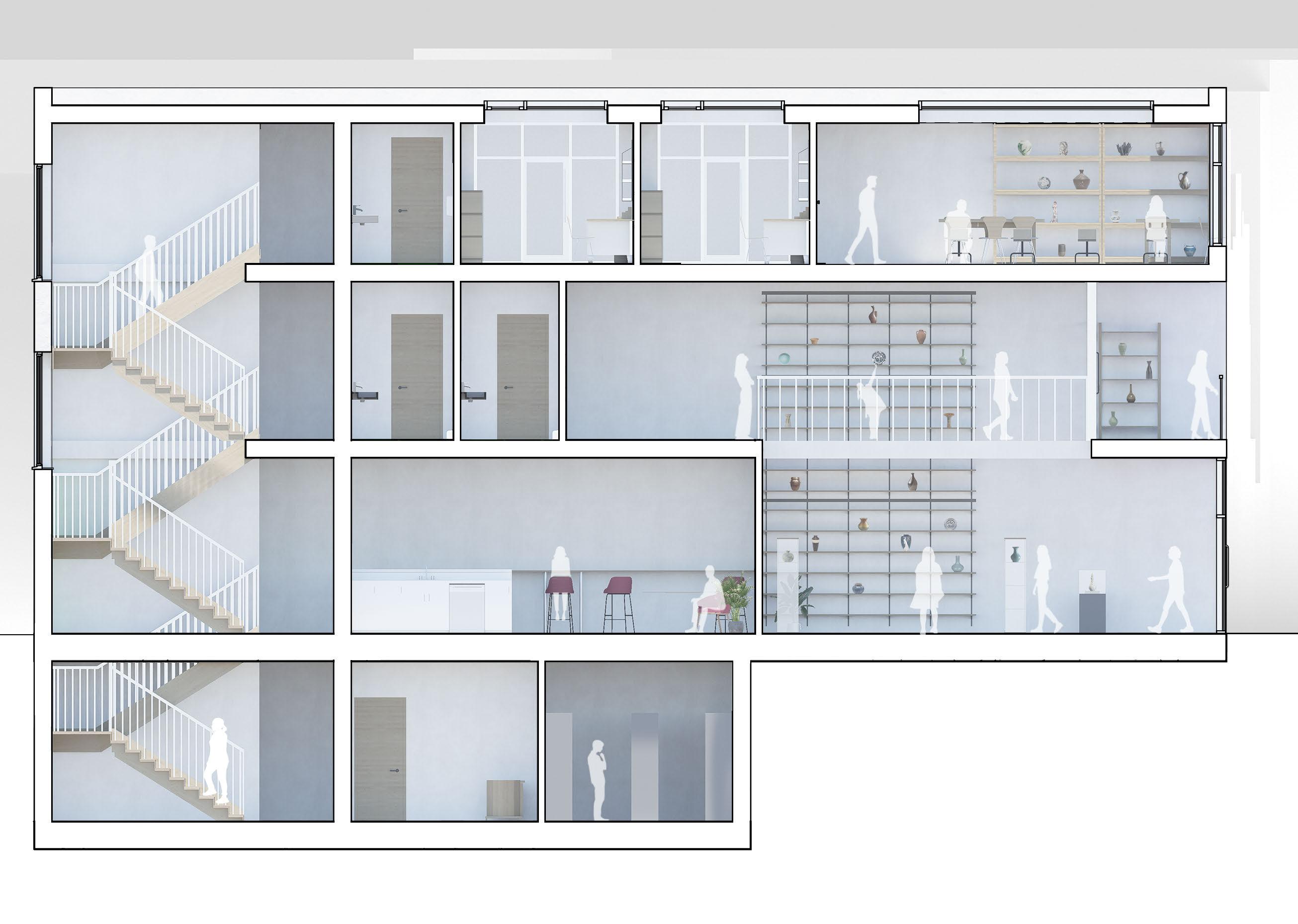
Section AA

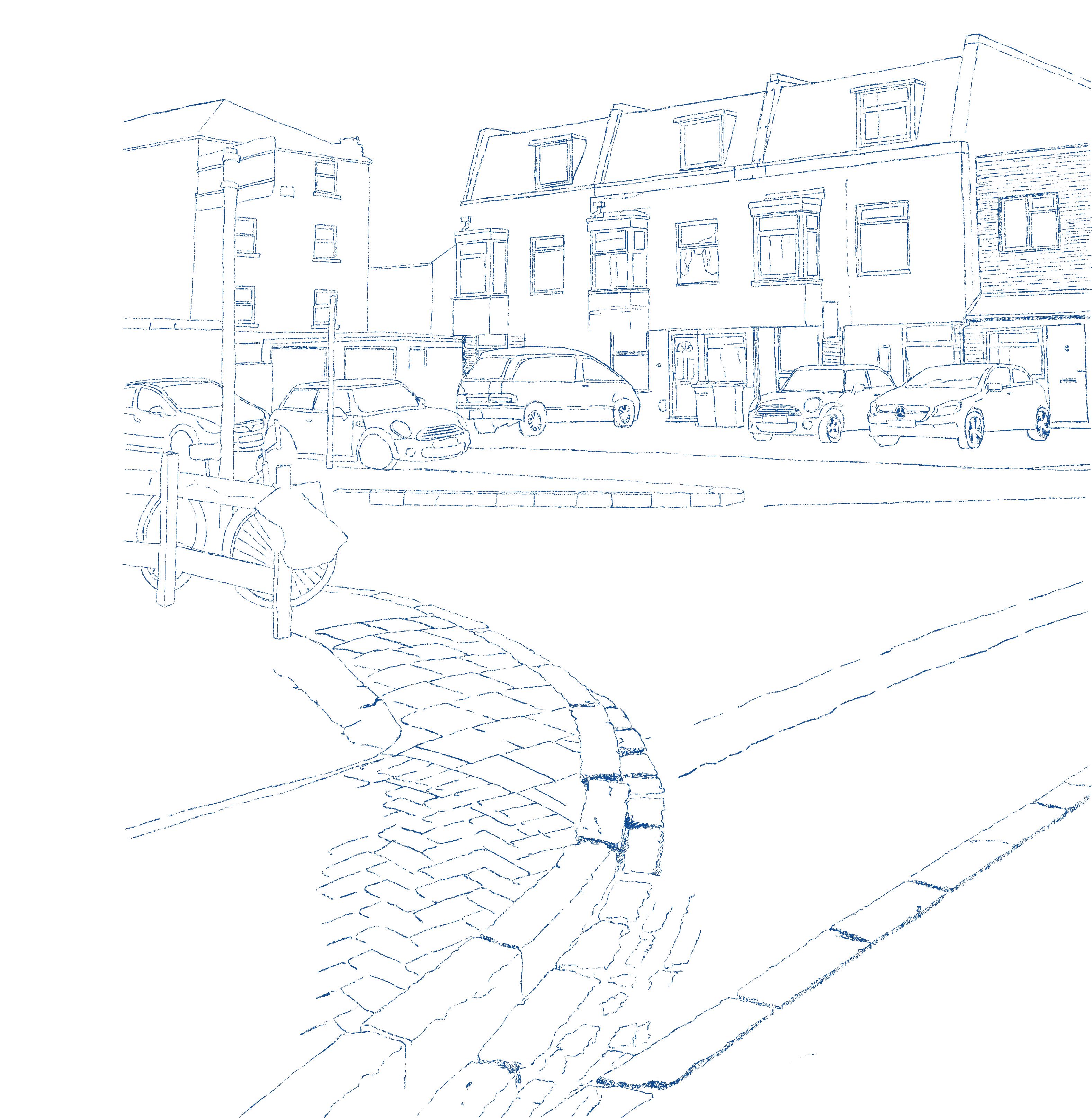

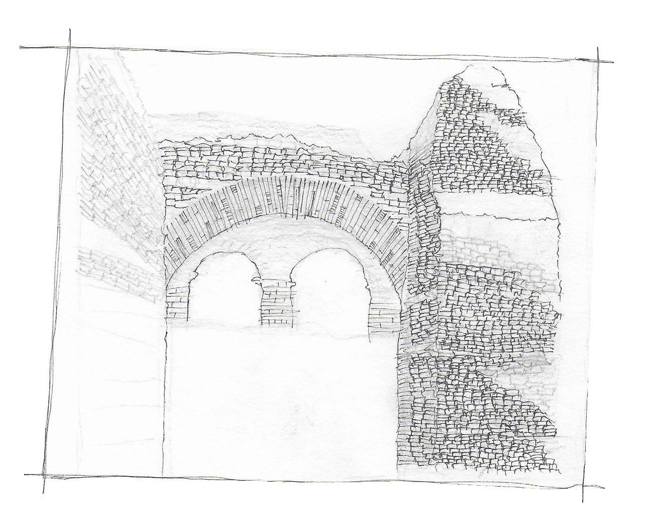
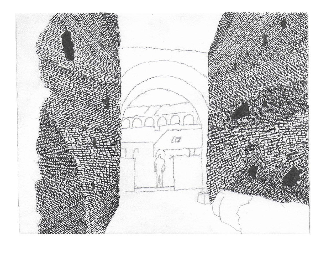
Art - Sketches 38 37 Email - jkuforiji76@gmail.com Phone number - 07848874448