Student Name
Dylan Lam
Determining the Sizing for a Heat Exchanger Condenser Aided by Aspen EDR
CHE210 - Heat and Mass Transfer Group 37
CHE Ltd Cooling Water Plant April 9, 2024
Student Number
1009092090
Yoonha Lee 1008889455
Jeslyn Lorraine Winoto 1008942780
1.0 Introduction and Objective
CHE Ltd. has requested a design for a heat exchanger condenser that will be used to liquify hexane (initially at 155 kPa and 105°C) A water cooling plant owned by CHE Ltd provides the required coolant at an inlet temperature of 32°C and outlet temperature of 49 °C. The sizing of the heat exchanger utilizes both Aspen EDR software and manual calculations
This report will delve into the methodology and calculation framework of our heat exchanger design given the predetermined design specifications from the client. The report will conclude with our recommendation for the sizings of the heat exchanger
2.0 Design Methodology
2.1 Assumptions
1) Mass flowrate of hexane is constant (7kg/s).
2) Heat transfer at the ends of the condenser is negligible.
3) The initial value for U is assumed to be 1000 W/m2K based on the upper bound value in a data table [1] (The upper bound value better fits the calculations for the heat exchanger).
4) Viscosity of the fluid at a wall temperature is assumed to be the same as the viscosity of the fluid at bulk temperature
5) Correction factor for pressure drop calculations is 1.
6) Fouling factor values (m2-K/W) were assumed to be 0 00018 and 0 0002 for Water and Hexane respectively
2.2 Input Data
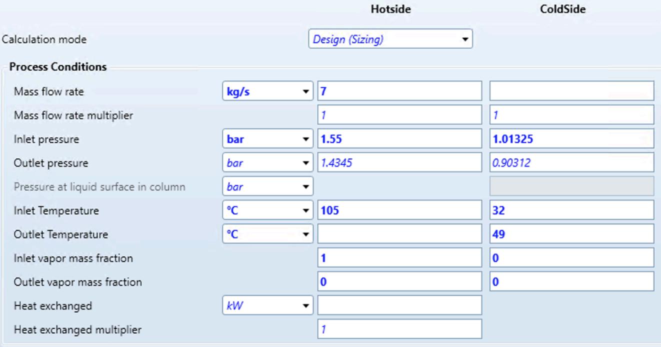
Figure 1: Input data into ASPEN EDR - Blue bold values are manual inputs, unbolded are values that were assumed by ASPEN.
2.3 Design Methodology Flowchart
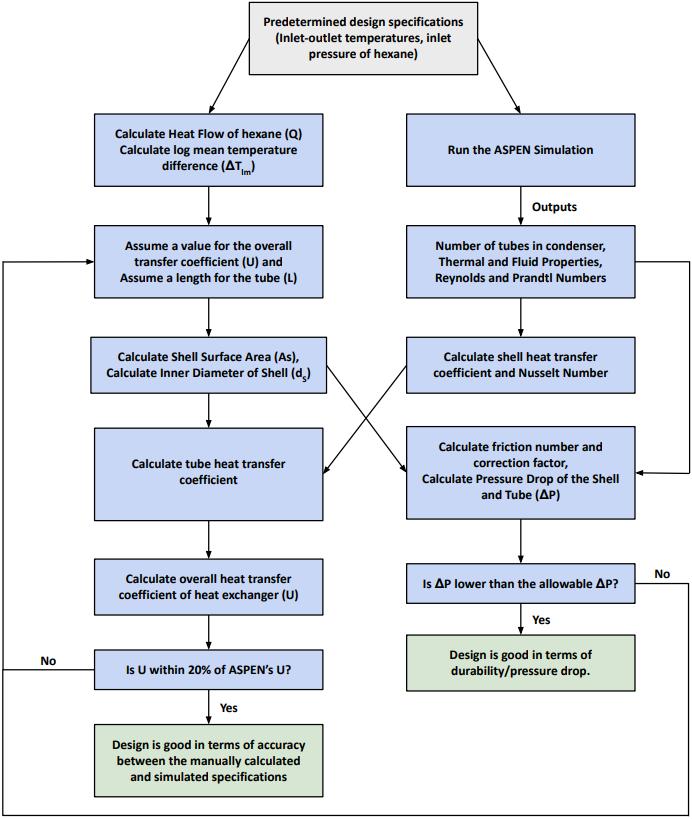
Figure 2: Design methodology flowchart of the heat exchanger sizing. See Appendix A for a more detailed step by step process accompanied with the equations used for each step
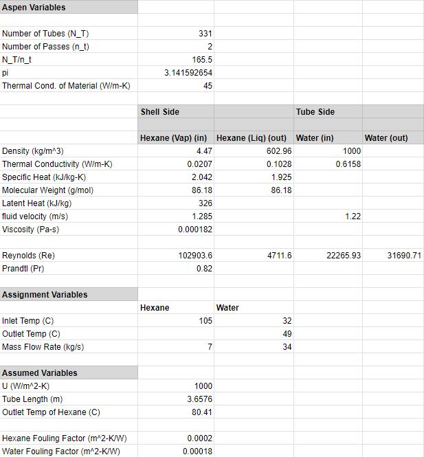
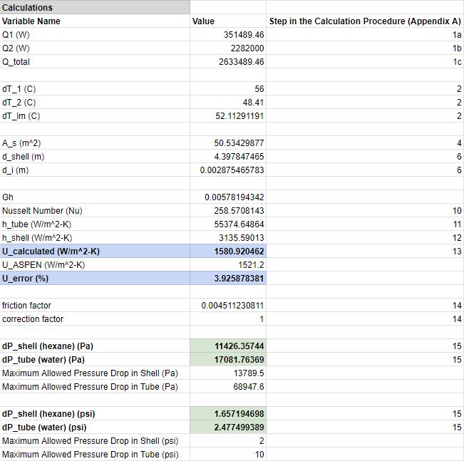
2.4 Calculations
Detailed calculations are provided in the Google Sheets spreadsheet (Appendix B), utilizing the formula outlined in the methodology above. The following table summarizes the key results obtained from our calculations.
Table 1: Variable and Calculated Results for the Condenser
3.0 Process Simulation Sizing Results
The ASPEN EDR simulation returned the following sizings for the main components of the condenser A complete sizing of the condenser can be seen on the TEMA Data Sheet in section 4.0.
Table 2: Main Sizings for the Condenser
4.0 TEMA Data Sheet

5.0 Discussion
The manual calculation resulted in the following sizings: Shell diameter of 4.398m, tube inner diameter of 0 002875m, tube length of 3 6576m, and a total of 331 tubes arranged in 2 passes The material for this condenser is carbon steel. These dimensions exhibit a notable disparity from the ASPEN data, which indicates a shell diameter of 539 75 mm and an inner tube diameter of 19 05 mm This discrepancy is most likely due to the Aspen EDR being a “black box” in terms of how it runs its calculations and where it sources its values for the parameters Also, the manual calculations assumed the viscosity of the fluid at the wall temperature to be equivalent to that at the bulk temperature, and conduction was considered negligible ASPEN likely uses complicated mathematical expressions instead of making these aforementioned assumptions, which causes a difference in final values.
Despite differences in the shell diameter, our calculations yielded acceptable results given our self-imposed constraints The manually calculated overall heat transfer coefficient (U) stands at 1580.92W/m²K, while the Aspen-provided U is 1521.2W/m²K. We achieved this by adjusting the tube length and our initial estimate for the iterated U value This results in a percent error of 3 93%, falling well within our self-imposed constraint of 20%. This constraint was determined to be a reasonable upper bound for error given the uncertainty regarding how ASPEN performs its calculations, and how much the value of U for organic vapor to water fluctuates depending on the database.
For shell and tube exchangers, it is generally recommended to aim for pressure drop values of <2psi for the tube and <10psi for the shell [3] The calculated pressure drop was 1 66psi for the shell pressure drop and 2.47psi for the tube pressure drop. Comparing this to the value provided by Aspen's TEMA data sheet, Aspen gives us pressure drop values of 1 51927psi for the shell side and 1 91754psi for the tube side. These values closely resemble the pressure drops that we calculated (max ±0.6 psi), further reinforcing the validity of the results from the calculation, and thus the viability of the sizings
6.0 Recommendation
We recommend using the sizing output given by Aspen for the heat exchanger. This includes an outer tube diameter of 19.05mm, an outer shell diameter of 558.7mm and an inner shell diameter of 539.75mm. The number of tubes within the exchanger is 331 and the length of the tube is 3657.6mm. The shell is made of carbon steel. This is because while we had done both iteration and simulation, we believe that the Aspen EDR yields stronger more accurate values due to the software having stronger optimization tools while the formulas in our manual analysis are more limited and less reliable for more complex situations.
7.0 References
[1] D. Galatro, “LECTURE 9: Heat Exchangers”, q.utoronto.ca. https://q.utoronto.ca/courses/332807/files/30990451?module item id=5597455 (accessed Apr. 09, 2024).
[2] “Hexane | Fisher Scientific,” www.fishersci.ca. https://www fishersci ca/ca/en/selection-guides/chemicals/hexane html
[3] A. Laval, “The theory behind heat transfer Plate heat exchangers,” 2004. Accessed: Apr. 09, 2024. [Online]. Available: https://www.alfalaval.com/globalassets/documents/microsites/heating-and-cooling-hub/alfa lav al heating and cooling hub the theory behind heat transfer.pdf
[4] “Condenser design : calculation method,” myengineeringtools com https://myengineeringtools.com/Thermodynamics/Condenser Calculation.html (accessed Apr. 09, 2024)
Appendix A : Design Calculation Procedure
1) Calculate the Q (heat flow) of the Hexane
a) Calculate Q1 - Heat transfer due to enthalpy change: �� = ���� �� ∆��
b) Calculate Q2 - Heat transfer due to phase change: �� = ��∆��
c) ������������ = ��1 + ��2
2) Calculate the log mean temperature difference (ΔTlm)
3) Assume a value for U of Organic vapor to water (See Table “Overall heat transfer coefficient” from L9 [1]) (Given as a range of values)
4) Calculate Shell Surface Area (AS): �� = ���� �� ∆�� ����
5) Assume a length for the heat exchanger
6) Calculate inner diameter of the shell using AS and assumed L: �� �� = �� �� �
7) Run ASPEN EDR simulation to determine the number of tubes in the heat exchanger (NT)
8) Obtain Reynolds and Prandtl numbers from ASPEN.
9) Since hexane undergoes phase change, calculate Re by taking the average Re of the two phases
10) Calculate the Nusselt Number using the following equation: [4] ���� = 0.027 · ����08 · ����1/3 · ( µ µ�� )014
Where:
μ = viscosity of the fluid at bulk temperature in Pa.s (kg/m/s)
μt = viscosity of the fluid a wall temperature in Pa s (kg/m/s)
Re = Average Reynolds number of the gas and liquid phase of hexane
11) Calculate heat transfer coefficient of the tube: [4] ���� = ℎ �������� �� �� λ ��
Where:
λC = Thermal conductivity of the cooling fluid (W/m-K)
12) Calculate heat transfer coefficient of shell.
13) Calculate overall heat transfer coefficient of the heat exchanger
14) Since the design is only valid if the pressure drop on both sides is less than the allowable pressure drop, calculate the friction number and the correction factor
As we assume the viscosity of fluid at bulk temperature is equal to the wall temperature, the correction factor will be 1
15) Obtain the pressure drop on the shell and the tube.