FIXING DESIGN GUIDE

MECHANICAL, CHEMICAL and LIGHT duty ANCHORS
2023-2024
Safe Anchoring
EDITION
With
ACCURATE CODE-COMPLIANT DESIGNS
Secure your work
Can be used according the different calculation rules and standards
ETA documents
BIM
WITH ALL BROWSERS
Always up to date Tablet, computer, smartphone
INTUITIVE
Easy 6 step process
For all kind of users

2D / 3D Interface for clear views
WWW.SPIT.COM/I-EXPERT @
FREE SOFTWARE
ENILNO
LIBRARY EMBEDED AUTOCAD & REVIT EN1992-4 BIM YSAE
FOREWORD
The design of fasteners are covering by European Standard EN 1992-4. In this technical guide, we propose technical sheets dedicated to each product with following data:
¬ General technical data on the product, ie. Dimensions, installation data, drawing, application, field of use, mechanical properties
¬ Minimum thickness of base material, minimum spacing and edge distance, characteristic spacing and edge distance.
¬ Characteristic resistances given in the ETA
¬ Recommended loads determined from performances and partial safety factors given in the ETA
¬ Design resistance Rd for each type of actions, ie. Static, Seismic, Fire depending on the scope of the approval All performances are determined from performances given in the ETA, and are guaranteed for spacing ≥ Scr and edge distance ≥ Ccr
¬ Performances for tensile load are given for the decisive failure for decisive failure type i.e. Pull-out failure, Concrete cone failure and Steel failure
¬ Performances for shear load are given for steel failure
To design easily your project, we recommend to use SPIT i-Expert software according to EN 1992-4
index
i-Expert Software
17
18
21 MECHANICAL ANCHORS 22 - 57 CHEMICAL ANCHORS 58 - 86 LIGHT DUTY ANCHORS 87 - 94
CONTENTS GENERALItY 02 -
product selection chart
-
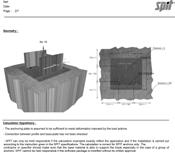
GENERALITY
TYPE OF ANCHORS
TORQUE CONTROLLED EXPANSION ANCHOR - TYPE A
The expansion is achieved by a torque acting on the screw or bolt, the intensity of the anchorage is controlled by this torque.
HAMMER SET EXPANSION ANCHOR - TYPE B
The expansion is achieved by impacts acting on a sleeve or cone. In the case of the SPIT GRIP anchor, the sleeve is expanded by driving in the cone, the anchorage being controlled by the length of travel of the cone.
UNDERCUT ANCHORS - TYPE C
Undercut anchors are anchored by mechanical interlock provided by an undercut in the concrete. The undercutting can be achieved by hammering or rotating the anchor sleeve into a drilled undercut hole, or by driving the anchor sleeve onto the tapered bolt in a cylindrical hole.
BONDED ANCHORS - TYPE D
Bonded anchors are anchored in drilled holes by bonding the metal parts to the sides of the drilled hole with a resin mortar. Tensile loads are transmitted to the concrete via bond stresses between the metal parts and the resin, and the resin and the concrete face of the drilled hole.
LIGHT DUTY PLASTIC ANCHORS
Plastic sleeves are expanded by hammering or screwing in the expansion element which presses the sleeve against the wall of the drilled hole. The expansion element could be a nail or a screw.
EUROPEAN STANDARDS
TORQUE CONTROLLED EXPANSION ANCHORS
CONCRETE SCREWS
UNDERCUT ANCHORS
HAMMER SET EXPANSION ANCHORS
BONDED ANCHORS
BONDED ANCHORS:
EAD 330747-00-0601
Post-installed rebar connections EAD 330087-00-0601
BONDED ANCHORS: for masonries
* Documents available on website: www.eota.eu DESIGN METHOD
ETA OPTIONS
Applications for
• «actual» risk of loss of human life
• serious economic consequences
• affect fitness of the structure to fulfil its functions
Applications for concrete with limited risk level
• «negligible» risk of human life
• low economic consequences
• localized damages
Anchors for multiple use in non-structural applications (typical example include pipework,ductwork and cable tray)
Application for rebar connections designed in accordance with Eurocode 2
Metal injection anchors for use in masonry
Anchors for fixing external thermal insulation composite systems with rendering
ETAG of plastic anchors for multiple use in concrete and masonry for non-stuctural applications
Design of anchors for use in concrete under quasi-static and seismic actions
OPTION N° CRACKED AND NON CRACKED NON CRACKED ONLY C20/25 ONLY C20/25 TO C50/60 ONE VALUE ACCORDING TO DIRECTION CHARATERISTIC & MINIMUM DISTANCES FOR SPACING, EDGE FRk FRk Ccr Scr Cmin Smin 1 • • • • • • • 2 • • • • • • • 3 • • • • • • • 4 • • • • • • • 5 • • • • • 6 • • • • • 7 • • • • • • • 8 • • • • • • • 9 • • • • • • • 10 • • • • • • • 11 • • • • • 12 • • • • • SUITABLE ANCHORS TYPE EUROPEAN STANDARDS* APPLICATION RANGE TORQUE CONTROLLED EXPANSION ANCHORS EAD 330232-00-0601
concrete
with high risk level
CONCRETE SCREWS UNDERCUT ANCHORS HAMMER SET EXPANSION ANCHORS BONDED ANCHORS EAD
330499-00-0601
EAD 330076-00-0604
EAD 330196-00-0604
INSULATION ANCHORS
EAD
LIGHT DUTY PLASTIC ANCHORS
330284-00-0604
EN 1992-4
2
For the design of anchorages according to the EN 1992-4 standard, the safety concept of partial safety factors shall be applied at the ultimate limit state. It shall be shown that the value of the design action Sd does not exceed the value of the design resistance Rd.
PRINCIPLE OF PARTIAL SAFETY CONCEPT
Case of ultimate limit state
Case of serviceability limit state
According to the EN 1992-4 design method, the proof of the resistance must be carried out for each following types of failures in tensile and shear load. The purpose of differentiating these failure modes, is to be able to apply an appropriate safety factor as a function of the specific failure mode.
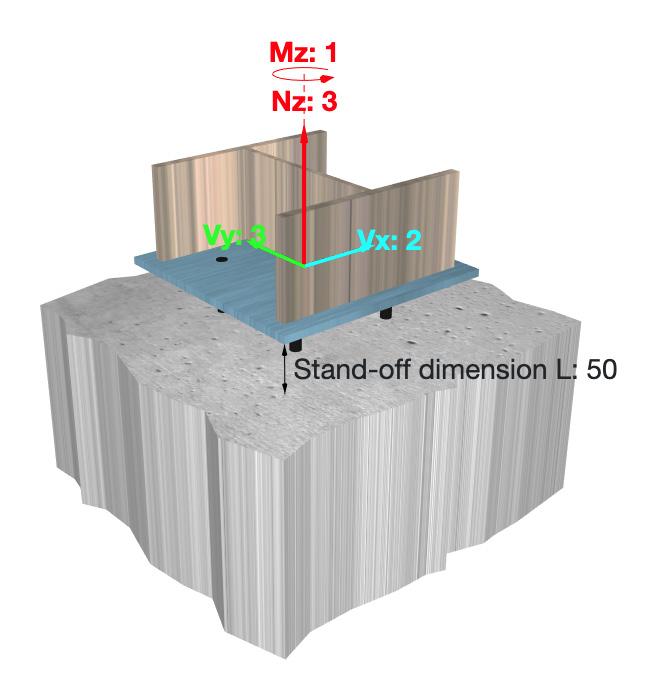
CALCULATION OF THE COMBINED LOAD
The combined load FSd with an angle α is obtained by:
FSd = (NSd)² + (VSd)² α = arctan (VSd/NSd)
with: NSd: action in tensile direction (NSd = FSd x cos α)
VSd: action in shear direction (VSd = FSd x sin α)
To verify the resistance for a combined load with the method CC, we proceed as follows :
‣ the tensile resistance: βN = NSd / NRd ≤ 1
‣ the shear resistance: βV = VSd / VRd ≤ 1
‣ the combined load with the following interactive equation: βN + βV ≤ 1,2
Sd ≤ Rd Mean
Characteristic resistance Design resistance Recommended load S< Rrec Design load (ELU) Actual load Sk Sd Rd Rrec Rk Ru,m Rk=Ru.m (1-k.v) Sd=Sk. Rrec = Rd
ultimate resistance
Mean
resistance Characteristic resistance Design resistance Design load Actual load Sk Sd Rk=Ru.m (1-k.v) Rd Rk Ru,m Sd=Sk Rd=Rk / M Sd < Rd GENERAL
ultimate
DIFFERENT TYPES OF FAILURE MODE N Concrete cone failure N Pull-out failure N Steel failure N Splitting failure TENSILE LOAD V Pryout failure V Steel failure V Concrete edge failure SHEAR LOAD
0.2 0.2 1.0 βN + βV ≤1,2 1.0 βV βN NSd FSd VSd
SAFETY CONCEPT 3
Seismic
The static or quasi-static loads are dead loads of the element fixed, permanent and variable actions as wind, snow …
DESIGN
The design actions for tensile and shear load in the ultimate limit state are calculated according to Eurocode 2 or 3.
In the simplest case: (permanent load «G» and one variable load «Q»), the design load is calculated as follows:
The factor 1,35 and 1,5 are the partial safety factor applied on the action. For simplification, in this book we have adopted the safety factor : γF = 1,4:
Sk = G + Q
Other cases:
The variable loads can be influenced by wind, or / and snow.
To calculate these actions in ultimate limit state, we will take the most unfavourable of the following actions combined. Details on Eurocode 1 for the loading codes.
4
TIME LOAD TIME PULSATING SHOCK ALTERNATIVE Static or quasi-static loads Dynamic loads Sd = 1.35 x G + 1.5 x Q Sd = γF . Sk
: G = permanent load QB = imposed load W = wind load Sn = snow load Ψ0 = 0,77 or all premises, except record offices and parking. If the basic variable action is the snow, Ψ0 is increase by 10%
Symbols
loads SEISMIC TIME PERMANENT LOAD VARIABLE LOAD ONE WITH ITS CHARACTERISTIC VALUE OTHERS WITH COMBINATION VALUE U.L.S. 1,35 G + 1,5 QB + 1,2 W 1,35 G + 1,5 W + 1,3 Ψ0 QB 1,35 G + 1,5 Sn + 1,3 Ψ0 QB TYPE OF LOADS
The seismic loads are calculated using the acceleration spectrum of the seismic zone, according to Eurocode 8. ACTION CALCULATION
The dynamic loads are variable actions in time with a medium or high amplitude. For example, motor vibration, regular shock … Some dynamic loads could be considered as quasi-static loads (wind …).
DESIGN ACTIONS
DESIGN RESISTANCE
CALCULATION OF THE DESIGN RESISTANCE
The design value of resistance Rd, in any direction and for all type of failure, is calculated from the characteristic resistance and the partial safety factor.
Rd = Rk γM
Rk : characteristic resistance of the anchor
γM : partial safety factor depends on the type of failure
CHARACTERISTIC RESISTANCE
The characteristic load of the anchor for concrete cone failure, in any direction, is calculated from the average value of the mean failure load for the single anchor, without the effect of spacing and edges. The characteristic load corresponds to the 5% - fractile of failure loads for the level of confidence (90%).
FRk = (1- k.v) . FRu,m
This calculation depends on number of tests (k) and the variation coefficient of tests (v)
Example : for a number of tests equal to 10 anchors, we can take k = 2,568.
The characteristic load of steel failure are calculated as follows:
For tensile load: NRk,s = A0.fuk [N] For shear load: VRk,s = 0,5.AS.fuk[N]
A0: min cross section [mm²]
As: stressed cross section [mm²] fuk: min tensile strength [N/mm²] fuk: min tensile strength [N/mm²]
CALCULATION OF PARTIAL SAFETY FACTOR
For concrete cone failure: γMc = γc γ1 γ2
γc: Partial safety factor for concrete under compression: γc = 1,5
γ1: Partial safety factor taking account of the scatter of the tensile strength of site concrete.
γ1 =1 for concrete produced and cured with normal care (EUROCODE 2 chap. 7)
γ2: Partial safety factor taking into account of the installation safety* of an anchor system
Tensile load:
γ2 = 1 for systems with high installation safety*
γ2 = 1,2 for systems with normal installation safety*
γ2 = 1,4 for systems with low but still acceptable installation safety*
Shear load:
γ2 = 1
For steel failure: γMs
γMs = 1,2 ≥1,4 fyk/fuk
γMs = 1,0 ≥1,25 fyk/fuk
For tensile load: For shear load: with fuk ≤ 800 N/mm² and fyk/fuk ≤ 0,8
γMs = 1,5 with fuk > 800 N/mm² or fyk/fuk > 0,8
* Installation safety means the influence of installation defects, such as diameter of drilled hole, cleaning of the hole, intensity of anchorage and striking the reinforcement during drilling.
5
SEISMIC PERFORMANCE
SEISMIC PERFORMANCE CATEGORIES C1 AND C2
The seismic performance of anchors subjected to seismic loading is categorized by performance categories C1 and C2. Seismic performance category C1 provides anchor capacities only in terms of resistances at ultimate limit state, while seismic performance category C2 provides anchor capacities in terms of both resistances at ultimate limit state and displacements at damage limitation state and ultimate limit state.
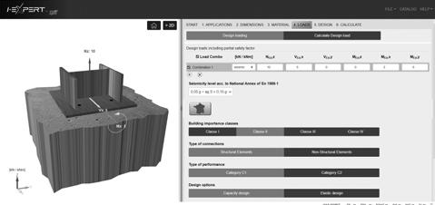
Table below relates the seismic performance categories C1 and C2 to the seismicity level and building importance class. The level of seismicity is defined as a function of the product ag.S, where ag is the design ground acceleration on Type A ground and S the soil factor both in accordance with EN 1998-1.
The value of ag or that of the product ag.S used in a Member State to define thresholds for the seismicity classes may be found in its National Annex of EN 1998-1 and may be different to the values given in Table below. Furthermore, the assignment of the seismic performance categories C1 and C2 to the seismicity level and building importance classes is in the responsibility of each individual Member State.
Tests
Category
RECOMMENDED SEISMIC PERFORMANCE CATEGORIES FOR METAL ANCHORS
a The values defining the seismicity levels are may be found in the National Annex of EN 1988-1
b Definition according to EN 1998-1:2004, 3.2.1
c ag = design ground acceleration on Type A ground (EN 1998-1:2004, 3.2.1), S = soil factor (see e.g. EN 1998-1:2004, 3.2.2).
d C1 for Type 'B' connections for fixings of non-structural elements to structures
e C2 for Type 'A' connections for fixings structural elements to structures
I Buildings and structures that normally are not subject to human occupancy (e.g., equipment storage sheds, barns, and other agricultural buildings) and that do not contain equipment or systems necessary for disaster response or hazardous materials.
II Most buildings and structures of ordinary occupancy (e.g., residential, commercial, and industrial buildings) except those buildings contained in other categories (less than 300 people, building high ≤ 28 m).
Buildings and structures that:
• Have large numbers of occupants (more than 300 people, building high ≥ 28 m) e.g., high-rise office buildings, sports arenas, and large theaters...
III
• Shelter persons with limited mobility (e.g., jails, schools, andsome healthcare facilities)
• Support lifelines and utilities important to a community’s welfare
• Contain materials that pose some risk to the public if released IV
Buildings and structures that:
• Are essential to post-earthquake response (e.g., hospitals, police stations, fire stations, and emergency communications centers)
• House very large quantities of hazardous materials
CATEGORY EUROPEAN REQUIREMENT ACCORDING TO TR 045 TECHNICAL REPORT ASSESSMENT OF TESTS ACCORDING TO ETAG 001 - ANNEX E
C1 for non-structural applications
tests in cracked-concrete (crack widths 0,5 mm)
Category
Alternative
C2 for structural and non-structural applications
crack
(crack
SEISMICITY LEVELa BUILDING IMPORTANCE CLASS ACC. TO EN 1998-1:2004, 4.2.5 CLASS Ag.Sc I II III IV Very lowb ag.S ≤ 0,05 g No additional requirement Lowb 0,05 g < ag.S ≤ 0,10 g C1 C1d or C2e C2 > Low ag.S > 0,10 g C1 C2
of increased severity with varying
widths, simulating earthquake
widths 0,8 mm)
CLASS BUILDING TYPE
6
I-EXPERT SOFTWARE I-EXPERT 7
Concrete is classified according to its compressive strength which is based on the classification per strength measured on cylinders as indicated in the NF EN 206-1 standard. For information, the table below gives an equivalence between the characteristic values and average strength on cylindrical and cubic specimens in MPa.
Concrete can be considered as cracked for many reasons. According to the ETA Guideline, we must verify if the concrete is cracked or non cracked by calculation of stresses in the works or part of the works serving as the base material (§4.7 - EN1992-4):
σL: Stresses in the concrete induced by external loads, including anchors loads
σR: Stresses in the concrete due to restraint of instrinsic imposed deformations (e.g; shrinkage of concrete) or extrinsic imposed deformations (e.g. due to displacement of support or temperature variations).
If no detailed analysis is conducted, then σR = 3N/mm² should be assumed, according to Eurocode 2.
If there are no details available to make the above calculation, use the table below. Nevertheless, it is the responsibility of the designer to check the status of the base material (cracked or non cracked).
CONCRETE CLASSES CHARACTERISTIC STRENGTH fck AVERAGE STRENGTH ACCORDING TO EUROCODE 2 ACCORDING TO P18-305 CYLINDER 16 X 32 CM CUBE 15 X 15 X 15 CM CYLINDER (fcm) 16 X 32 CM CUBE 15 X 15 X 15 CM CUBE 20 X 20 X 20 CM C 16/20 B16 16 20 20 25 24 C 20/25* B20 20 25 25 31 29 C 25/30 B25 25 30 30 37 36 C 30/37* B30 30 37 37 46 43 C 35/45 B35 35 45 45 56 53 C 40/50* B40 40 50 50 62 59 C 45/55 B45 45 55 55 69 65 C 50/60* B50 50 60 60 72 68 * The most usual classes WORKS OR PARTS OF WORKS USED AS ANCHORING BASE CONCRETE CONDITIONS NON CRACKED CRACKED Deflected elements (slabs, longitudinal beam, firder, purlin) in reinforced concrete X Deflected elements (slabs, longitudinal beam, firder, purlin) in prestressed concrete X Outside wall of a building in not reinforced (according to BAEL) or with reinforced skin X Outside wall of a building in reinforced concrete X Inside wall of a building X Angle or edge post X Inside post X Base plate paving X Keying areas of a building made from prefabricated elements X Ends of deflected elements (ex: projected balcony noses) X Tanking X CONCRETE STRENGTH FIELD OF USAGE: CRACKED OR NON CRACKED CONCRETE σL+ σR ≤ 0
8
CONCRETE
The following are examples of non-cracked locations in simple structures (issue from the technical report n° CEN/TC250/SC2/WG2 “effect of cracking” published by CEN.
Solid slabs, beams - simply supported
Solid slabs, beams, ribbed floors - Continuous
Cantilever slabs
Cantilever beams
0.15L L L h h h h 0.4h 0.4h 0.4h A A – A A – A A – A B – B B – B 0.15L 0.25L L 0.25L 0.15L1 0.15L2 0.15L3 L1 L2 L3 0.15L1 0.25L2 0.25L1 0.25L3 0.25L2 0.15L2 B AB A A B B A A A A B B C C Non-cracked concrete Non-cracked concrete Non-cracked concrete Non-cracked concrete
CONCRETE 9
MASONRIES
Perforated clay bricks type ECO-30, rendered or not rendered

Rc = 3.7 N/mm² - 57x20x30 (cm)
NF EN 771-1
Rc = 14.5 N/mm² - 20x24x50
NF EN 771-1
Clay bricks
Rc = 55 N/mm² - 22x10x5.5 (cm)
NF EN 771-1
Solid concrete blocs B120 Rc = 13,5 N/mm² - 20x20x50 (cm)


Hollow concrete block type B40, rendered or not rendered Rc = 6,5 N/mm² - 20x20x50 (cm)
NF EN 771-3
Plasterboard type BA13 and BA10 + polystyrene


NFP 72-302
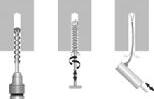
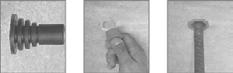
FIXINGS OF REBARS AND THREADED STUDS M8 TO M20 IN CEILING
USING CEILING CAP AND MEASURING CONNECTOR: USING SIEVE
Aerated
concrete
1 - Resin injection (EPOBAR for rebars or VIPER XTREM for studs) with measuring connector
2 - Cap introduction into drilled hole
3 - Installation : the rebar (or the stud) is maintained by the cap blades
d L
The design resistances for stud dimensions M8 to M20 in ceiling are reduced by 20 % for anchoring with resin.

1 - Drill a hole according to the diameter and the selected depth
2 - Carefully clean with metal brush
3 - Remove the dust by blowing with air pump
4 - Cut a length of screen corresponding to the length Lt of the table above and insert the cap
5 - Insert the threaded stud in the cap and push it into the sieve to the length lr of the table above
6 - Fill the remaining volume of sieve with resin
l
7 - Insert the assembly in the hole until the cap locks itself in the hole
8 - Push the stud by hand with a twisting motion through the cap to the bottom of the hole. A slight excess of resin should emerge
STUD DIMENSION MIN. SUPPORT THICKNESS HOLE DIAMETER HOLE DEPTH STUD LENGTH INSERTED INTO SIEVE INTERNAL DIAMETER OF THE SIEVE SIEVE LENGTH SIEVE CODES CAP TYPES CAP CODES (mm) d0 (mm) h0 (mm) lr (mm) dt (mm) lt (mm) M8 120 15 80 10 12,5 75 63400 W5 63460 M10 130 15 90 10 12,5 85 63400 W5 63460 M12 160 18 110 15 15 105 63410 W7 63470 M16 175 22 125 50 20,5 120 63420 W10 63480 M20 220 28 170 65 26 165 63430 W13 63490
Mvn
NF EN 771-3 NF
= 500 kg/m3
EN 771-4
Engineer clay bricks Murbric type T20, rendered or not rendered
9 - Observe loading and tightening torque times
Characteristics of these sieve and installation data :
10
OTHER SUBSTRATE/CEILING
STEEL PROPERTIES
Mechanical characteristics
The steel properties are determined by : - the tensile strength fuk (N/mm²), - the yield strength fyk (N/mm²).
Zinc coated steel: the standard NF EN 20898-1 gives the characteristics of studs and screws depending on the grade of steel. Stainless steel: the standard NF EN 25100-0 gives the stainless steel characteristics.
TORQUE WRENCH SOCKETS / NUTS / WASHERS
NUTS: dimensions for torque wrench sockets
WASHERS: dimensions of the washers used with SPIT Products (some products are available with large washers)
NOMINAL THREAD DIAMETER THREAD PITCH NOMINAL CROSS SECTION STEEL GRADE STAINLESS STEEL GRADE A4 3.6 4.6 4.8 5.6 5.8 6.8 8.8 10.9 12.9 50 70 80 (mm) (mm) As/mm² Minimum failure load Minimum failure load 1.6 0.35 1.27 0.42 0.51 0.53 0.64 0.66 0.76 1.02 1.32 1.55 0.64 0,89 1.02 2.0 0.4 2.07 0.68 0.83 0.87 1.04 1.08 1.24 1.66 2.15 2.53 1.04 1,45 1.66 2.5 0.45 3.39 1.12 1.36 1.42 1.70 1.76 2.03 2.71 3.53 4.14 1.70 2,37 2.71 3.0 0.5 5.03 1.66 2.01 2.11 2.51 2.62 3.02 4.02 5.23 6.14 2.51 3,52 4.02 3.5 0.6 6.78 2.24 2.71 2.85 3.39 3.53 4.07 5.42 7.05 8.27 3.39 4,74 5.42 4.0 0.7 8.78 2.90 3.51 3.69 4.39 4.57 5.27 7.02 9.13 10.70 4.39 6,15 7.02 5.0 0.8 14.2 4.69 5.68 5.96 7.10 7.38 8.52 11.35 14.80 17.30 7.10 9,94 11.35 6.0 1.0 20.1 6.63 8.04 8.44 10.00 10.40 12.10 16.10 20.90 24.50 10.00 14,07 16.10 7.0 1.0 28.9 9.54 11.60 12.10 14.40 15.00 17.30 23.10 30.10 35.30 14.40 20,23 23.10 8.0 1.25 36.6 12.10 14.60 15.40 18.30 19.00 22.00 29.20 38.10 44.60 18.30 25,62 29.20 10.0 1.5 58.0 19.10 23.20 24.40 29.00 30.20 34.80 46.40 60.30 70.80 29.00 40,60 46.40 12.0 1.75 84.3 27.80 33.70 35.40 42.20 43.80 50.60 67.40 87.70 103.00 42.20 59,01 67.40 14.0 2.0 115.0 38.00 46.00 48.30 57.50 59.80 69.00 92.00 120.00 140.00 57.50 80,50 92.00 16.0 2.0 157.0 51.80 62.80 65.90 78.50 81.60 94.00 125.00 163.00 192.00 78.50 109,90 125.00 18.0 2.5 192.0 63.40 76.80 80.60 96.00 99.80 115.00 159.00 200.00 234.00 96.00 134,40 159.00 20.0 2.5 245.0 80.80 98.00 103.00 122.00 127.00 147.00 203.00 255.00 299.00 122.00 171,50 203.00 22.0 2.5 303.0 100.00 121.00 127.00 152.00 158.00 182.00 252.00 315.00 370.00 152.00 212,10 252.00 24.0 3.0 353.0 116.00 141.00 148.00 176.00 184.00 212.00 293.00 367.00 431.00 176.00 247,10 293.00 27.0 3.0 459.0 152.00 184.00 193.00 230.00 239.00 275.00 381.00 477.00 560.00 230.00 321,30 381.00 30.0 3.5 561.0 185.00 224.00 236.00 280.00 292.00 337.00 466.00 583.00 684.00 280.00 392,70 466.00 33.0 3.5 694.0 229.00 278.00 292.00 347.00 361.00 416.00 576.00 722.00 847.00 347.00 485,80 576.00 36.0 4.0 817.0 270.00 327.00 343.00 408.00 425.00 490.00 678.00 885.00 997.00 408.00 571,90 678.00 39.0 4.0 976.0 322.00 390.00 410.00 488.00 508.00 586.00 810.00 1020.00 1200.00 488.00 683,20 810.00 Sw M Ø e d1 d2 s
WASHERS ACCORDING TO NF EN ISO 7091 SPECIAL WASHERS SPIT TRIGA Z XTREM WASHERS SPIT TRIGA Z A4 (mm) d2 d1 s d2 d1 s d2 d1 s M6 12 6,6 1,6 18 6,7 2 18 6,3 2 M8 16 9,0 1,6 20 8,7 2 22 8,2 2 M10 20 11,0 2 26 10,5 3 28 10,5 3 M12 24 13,5 2,5 30 12,5 3 30 12,3 3 M16 30 17,5 3 40 16,7 4 - -M20 37 22,0 3 45 20,7 4 - -M24 44 26,0 4 - - - - -M30 56 33,0 4 - - - - -NUTS ACCORDING TO DIN 934 NUTS ACCORDING TO NF EN ISO 4032 (mm) Sw e M Sw e M M6 10 11,5 5 10 11,05 5,2 M8 13 15 6,5 13 14,38 6,8 M10 17 19,6 8 16 17,77 8,4 M12 19 21,9 10 18 20,03 10,8 M16 24 27,7 13 24 26,75 14,8 M20 30 34,6 16 30 32,95 18 M24 36 41,6 19 36 39,55 21,5 M30 46 53,1 24 46 50,85 25,6
MECHANICAL CHARACTERISTICS STEEL GRADE STAINLESS STEEL GRADE* 3.6 4.6 4.8 5.6 5.8 6.8 8.8 10.9 12.9 50 70 80 Min. tensile strength fuk (N/mm²) 330 400 420 500 520 600 800 1040 1220 500 700 800 Min yield strength fyk (N/mm²) 190 240 340 300 420 480 640 940 1100 210 450 600 * Stainless steel grade A1, A2 & A4
Minimum failure loads (kN) - ISO metric thread to NF EN 20898-1
STEEL MECHANICAL PROPERTIES
11
CHOICE OF STEEL QUALITY ACCORDING TO ATMOSPHERE
Atmospheric corrosion is linked to ambient atmosphere. The agents combined themselves to air components. The mixture of oxygen, moisture and industrial pollutants, mainly chlorous and sulphurous, attacks and destroys metals and alloys. We can indicate 6 principal types of atmosphere.
DRY Clean rooms, heated in winter without condensation. Housing inside, air-conditioned rooms.
HUMID Rooms subjected to condensation, warehouses, stores, cellars...
RURAL Housing in temperate climate and a long way from large cites and factories (country).
URBAN Housing in towns with one or more factories emitting smoke creating atmospheric corrosion.
INDUSTRIAL Factories and their surroundings significant atmospheric corrosion (depending on industrial process).
SALT ATMOSPHERE Atmosphere of seaside or on sea. High corrosion due to presence of relatively high humidity combined with certain contents of sea salt in the air.
Source : NFA 91-102 - Metal surface Quality not suitable for the medium Get into touch with us Possible use
CHOICE OF STEEL QUALITY ACCORDING TO CONTACTS BETWEEN MATERIALS
Electrolytic corrosion may occur when two different metals are in contact with each other. This creates an electrolytic action which causes the gradual destruction of one of the elements.
TYPES OF ATMOSPHERE ZINC DEPOSIT 5-10 µm HOT DIP GALVANIZED 45 µm MINI STAINLESS STEEL A4
INSIDE
OUTSIDE
METAL OF THE PART TO BE FIXED METAL OF THE FIXING STAINLESS STEEL HOT DIP GALVANISED ZINC COATED STEEL ZINK ALLOY BRASS Stainless steel Hot dip galvanised steel Zinc coated steel Mild steel Aluminium alloy No corrosion of the fixing Moderated corrosion of the fixing Corrosion of the fixing
12
CORROSION
COATINGS AND CORROSION RESISTANCE
Type of coating
1600
1400
1200
1000
800
1800 > 5000 FRANCE NF EN 10088-1 ACCORDING TO NFA 35-573 1990 NFA 35-574 1990 (OR NFA 36-209 OR NFA 35-577)
600
Sherardisation (20 µm)
Hot dip galvanised (70 µm)
Electrogalvanised with thickness coating (5-7 µm)
TABLE OF PRINCIPAL AUSTENITIC STAINLESS GRADES
Sherardisation (35 µm)
steel (316L) 400
Stainless 200
USA GERMANY SWEEDEN U.K. ITALY QUALITY GRADE SYMBOL CODE AISI WERKSTOFF DIN SIS BS 970 UNI X2 CrNi 19-11 14306 Z3 CN 18-10 304 L 1.4306 X2 Cr Ni 18-09 2352 304-512 X2 CrNi 18-11 A2L Z3 CN 19-11 X5 CrNi 18-10 14301 Z6 CN 18-09 304 1.4301 X5 Cr Ni 18-09 2332 304-515 X5 CrNi 18-10 A2 Z7 CN 18-09 X10 CrNi 18-8 14310 Z11 CN 17-08 ≈ 302 1.4300 X12 Cr Ni 18-09 2330/31 302-525 X10 CrNi 18-09 A2 Z11 CN 18-08 Z12 CN 18-09 X4 CrNi 18-12 14303 Z5 CN 18-11 305 1.4303 X5 CrNi-19-11 305-519 X8 CrNi 18-12 A2 X6CrNiTi 18-10 14541 Z6 CND 18-10 321 1.4541 X10 CrNiTi 18-09 2337 321-512 A3 X5CrNiMo 17-12-2 14401 Z6 CND 17-12 316 1.4401 X5CrNiMo 18-10 2343 316-516 X5CrNiMo17-12 A4 X6 CrNiMoTi 17-12-2 14571 Z6 CNDT 17-11 316 Ti 1.4571 X10CrNiTi 18-10 2334 320-517 X6CrNiMoTi17-12 A5 X2 CrNiMo 17-13-3 14404 Z3 CND 17-12 316 L 1.4404 X2CrNiMo 18-10 2353 316-512 X2CrNiMo17-12 A4L X2CrNiMoN17-13-3 14406 Z3 CND 17-11 AZ A4L X3CrNiCu 18-9-3 14560 Z4 CNU 19-09 FF A2
CORROSION 13
Dacromet 500 grade A (5 - 7 µm)
Exposure time
saltspray (hours)
to
Dacromet 500 grade B (8 - 10 µm) 0
Length: 1 mm = 0,1 cm = 0,0394 in (pouce)
Force: 1 kN = 100 daN = 1000 N ~ 100 kg
1 kg = 9,81 N
1 N = 0,2248 lbf (livre-force)
Concrete compressive strength:
1 MPa = 1 N/mm² = 10 kg/cm²
1 MPa = 10 bars
1 N/mm² = 149,2 lbf/in² (pound-force per square inch)
METRIC IMPERIAL FACTOR CONVERSION UNITS SYMBOLS UNITS SYMBOLS IMPERIAL/METRIC METRIC/IMPERIAL Concrete strength newton per square mm N/mm2 (=MPa) livre-force per square inch lbf/in2 (=psi) 1 lbf/in2 = 0,00689 N/mm2 1 N/mm2 = 145,0 lbf/in2 Tightening torque newton-meter Nm pound-force foot lbf/ft 1 lbf ft = 1,356 Nm 1 Nm = 0,738 lbf ft Mass ton t pound Lb 1 lb = 0,00454 t 1 t = 220,26 lb ton t ton t 1 t = 1,016 t 1 t = 0,9842 t kilogram kg pound lb 1 lb = 0,4536 kg 1 kg = 2,204 lb Force kilonewton kN ton-force tf 1 tf = 0,10036 kN 1 kN = 9,9640 tf kilonewton kN pound-force lbf 1 lbf = 0,004448 kN 1 kN = 224,8 lbf newton N pound-force lbf 1 lbf = 4,448 N 1 N = 0,2248 lbf Length meter m foot ft 1 ft = 0,3048 m 1 m = 3,2808 ft centimeter cm inch in 1 in = 2,54 cm 1 cm = 0,3937 in millimeter mm inch in 1 in = 25,4 mm 1 mm = 0,03937 in Area square millimeter mm2 square inch in2 1 in2 = 645,16 mm2 1 mm² = 0,0015 in2 Temperature Celsius degree °C Fahrenheit degree °F 1°F = (9/5 °C + 32) 1°C = 5/9 (°F - 32) 0 °C = 32 °F 30 °C = 86 °F 10 °C = 50 °F 40 °C = 104 °F 20 °C = 68 °F 50 °C = 122 °F
UNITS 14
UNITS CONVERSION TABLE
TERMINOLOGY
Actions
Sk Action on the anchor at the serviceability limit state (ELS)
Sd Action on the anchor at the ultimate limit state (ELU)
Resistances of the anchor
Ru,m Mean ultimate resistance
Rk Characteristic resistance
Rd Design resistance
Frec Recommended resistance
Types of resistance
uncr Resistance for non-cracked concrete
cr Resistance for cracked concrete
C1 Resistance for seismic loads category C1
C2 Resistance for seismic loads category C2
fi,R Resistance for fire exposure
Types of load
N Tensile force (NSd, NRu,m, NRk, NRdp, NRds, NRdc, Nrec)
V Shear force (VSd, VRu,m, VRk, VRds, VRdc, Vrec)
F Oblique force (FSd, FRu,m, FRk, FRds, FRdc, Frec)
M Bending moment (MRk, MRec)
Anchor technical data
hef Effective anchorage depth
hnom Embedment depth in the concrete
h0 Drilling depth
d Thread diameter
d0 Drilling diameter
df
Clearance hole diameter in the part to be fixed
dnom External diameter of the anchor
L Total anchor length
l2
Threaded length
Tinst Required setting torque
tfix
hmin
Thickness of the part to be fixed
Minimum thickness of base material
Distances
S Distance between 2 anchors
Scr Spacing for ensuring the realisation of the characteristic resistance
Smin Minimum allowable spacing
Cmin Minimum allowable edge distance
Ccr,N Edge distance for ensuring the realisation of the characteristic tensile resistance
Concrete and steel
fcm Average concrete compression strength
fck
fuk
fyk
Characteristic concrete compression strength
Characteristic steel ultimate strength
Characteristic yield strength
SYMBOLS USED L d0 hef tfix df Tinst hmin h0 d N V F S C V C fck fcm fuk
15
TESTING
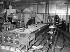
SPIT LABORATORY
At SPIT we have our own laboratory to test all types of fixings in any base material. This laboratory is used for new product development, approvals and quality control.
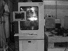
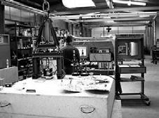
Our laboratory is accredited by COFRAC in accordance with programme 39.2 «testing of mechanical anchors - Part 2 : Expansion Anchors». Tests for metal anchors in concrete are carried out in accordance with TR048 and TR049.
To carry out these tests, the laboratory is equipped with high performance test benches able to apply pull out loads up to 80 tonnes. Shear tests, long term load tests, pulsating load tests, tests in static cracks from 0,3 mm to 0,5 mm, tests in dynamic cracks, and seismic tests for qualification of anchors C1 & C2 categories, are also carried out on these equipments. EQUIPMENT
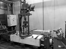
FOR TESTING IN CRACKED CONCRETE
PULL
OUT EQUIPMENT TEST
OVEN TO TEST THE BEHAVIOUR AT HIGH TEMPERATURE FOR CHEMICAL RESINS
SEISMIC TEST BENCH
16
I-calc
I-CALC App : Resin volume calculator for SPIT Adhesive cartridges


I-CALC App allows you to determine the number of SPIT Adhesive cartridges that you need on your jobsite for installation of reinforcement rebars or studs. The number of cartridges required can be easily adjusted based on the installation quality you choose.

Android app on Available on the
I-CALC APP
17
i-CALC APPLICATION
product selection chart
TYPE OF ANCHORS Anchor diameter Stainless steel Approvals Crack concrete Seismic HEAVY DUTY MECHANICAL ANCHORS TRIGA Z XTREM M6 - M20 ETA 05/0044 TRIGA Z XTREM A4 M8 - M16 GUARDIA - GUARDIA A4 M12 ETA 07/0047 FIX Z XTREM M8 - M20 ETA 15/0388 FIX Z XTREM A4 M8 - M16 ETA 15/0388 FIX3 M6 - M20 ETA 13/0005 TAPCON XTREM Ø8 - Ø14 ETA 16/0276 TAPCON XTREM LT A4 Ø6 - Ø10 ETA 22/0364 TAPCON Ø5 - Ø6 ETA 16/0373 (1) - ETA 16/0276 Ø6 GRIP+ L & GRIP+ A4 M6 - M16 ETA 21/0176 MEDIUM DUTY MECHANICAL ANCHORS PRIMA M6 - M12 SOCOTEC KX 0827 TRINEO/B M6 - M10 ETA 22/0628 - ETA 22/0883 DYNABOLT M6 - M12 CHEMICAL ANCHORS MAXIMA + Studs Zn & A4 M8 - M30 ETA 18/0197 EPCON C8 XTREM - Studs Zn & A4 M8 - M30 ETA 10/0309 - ETA 07/0189(2) EPCON C8 XTREM - Starter bars Ø8 - Ø30 ETA 10/0309 VIPER XTREM - Studs Zn & A4 M8 - M30 ETA 17/0514 - ETA 17/0513(2) VIPER XTREM - Multicone studs M12 - M20 ETA 17/0514 VIPER XTREM - Starter bars Ø8 - Ø20 ETA 17/0514 ATP - ATP A4 M8 - M20 MULTI-MAX - Studs Zn & A4 M8 - M24 ETA 13/0435 - ETA 13/0436(2) MULTI-MAX - Masonry M8 - M12 ETA 13/0437 C-MIX PLUS - Masonry M8 - M16 SOCOTEC 18056808000007 EASYMIX M8 - M10 SOCOTEC 18046808000010 LIGHT DUTY ANCHORS PROLONG Ø10 - Ø16 ETA 17/0202 B-LONG XTREM - B-LONG XTREM A4 Ø8 - Ø10 ETA 13/1068 - ETA 20/0542 HIT M - HIT M A2 Ø5 - Ø8 ETA 06/0032 (1) Non stuctural applications (2) For post-installed rebars applications European Technical Assessment ETA STAINLESS STEEL A4/A2 SOCOTEC
18


Fire resistance Waterproof Concrete Stone/Solid concrete block/ Solid brick Hollow concrete block/ Hollow brick Plasterboard Aerated concrete Beam slab Page 22 25 28 30 33 36 38 41 44 47 50 53 56 58 60 63 66 69 72 75 77 79 81 84 87 89 92 SUITABLE POSSIBLE USE WATERPROOF
chart 19
product selection
OTHER ANCHORS
Technical data sheets for the SPIT products listed below are available on our website: www.spitpaslode.com
TYPE OF ANCHORS Anchor diameter Approvals Crack concrete Fire resistance HEAVY DUTY MECHANICAL ANCHORS TAPCON PLUS Ø10 - Ø14 LIGHT DUTY ANCHORS L M10 ACS Ø10 UDZ Ø6 ETA 05/0038 (1) SDA Ø6 ETA 10/0166 (1) P6 & G8 Ø6 - Ø8 RM6 M6 LAITON M4 - M8 STELLIX M4 - M6 ZENTECH M4 - M6 CC M4 - M6 DRIVA & DRILL Ø4,5 - Ø3 DRIVA CLICK Ø4,5 PRO6 Ø5 - Ø14 COLORTECH Ø5 - Ø8 NYL Ø5 - Ø14 ARPON M6 - M8 INSULATION ANCHORS PTH-KZ Ø8 ETA 18/1103 PTH-S Ø8 ETA 18/1102 PTH-X Ø8 ETA 18/1095 PTH-SX Ø8 ETA 18/1101 ISO Ø10 ETA 04/0076 CB Ø8 ISOMET Ø8 SOCOTEC PT 3043 ISOWOOD Ø4,5 (1) Non stuctural applications European Technical Assessment ETA
SOCOTEC
20


 Concrete
Stone/Solid concrete block/ Solid brick
Concrete
Stone/Solid concrete block/ Solid brick
Base material : wood only SUITABLE POSSIBLE USE
21
Hollow concrete block/ Hollow brick Plasterboard Aerated concrete
OTHER ANCHORS
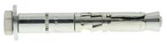
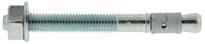
TRIGA Z XTREM
TECHNICAL DATA
RANGE Min. anchor depth Max. thick. of part to be fixed Min. thick. of base material Thread Ø Drilling depth Drilling Ø Clearance Ø Total anchor length Tighten torque Code (mm) (mm) (mm) (mm) (mm) (mm) (mm) (mm) (Nm) h ef t fix h min d h 0 d 0 df L T inst V6-10/5 50 5 100 M6 70 10 12 65 15 050673 V6-10/20 20 80 050674 V8-12/1* 60 1 120 M8 80 12 14 65 25 050677 V8-12/10 10 80 050678 V8-12/20 20 90 050679 V8-12/50 50 120 053001 E8-12/20 20 99 050681 E8-12/55 55 134 050684 V10-15/1* 70 1 140 M10 90 15 17 75 50 050687 V10-15/10 10 95 050688 V10-15/20 20 105 050689 V10-15/55 55 140 053003 E10-15/20 20 114 050691 E10-15/35 35 129 050692 E10-15/55 55 149 050693 V12-18/1* 80 1 160 M12 105 18 20 80 80 053905 V12-18/10 10 105 050696 V12-18/25 25 120 050697 V12-18/55 55 150 053004 E12-18/25 25 132 050698 E12-18/45 45 152 050699 E12-18/65 65 172 050701 E12-18/100 100 207 050702 V16-24/10 100 10 200 M16 131 24 26 130 120 050704 V16-24/25 25 145 050705 V16-24/50 50 170 050710 E16-24/25 25 159 050706 E16-24/55 55 189 050707 E16-24/100 100 234 050708 V20-28/25 125 25 250 M20 157 28 31 170 200 050711 E20-28/25 25 192 050712 E20-28/60 60 227 050713 E20-28/100 100 267 050714 TF V8-12/16 60 16 120 M8 80 12 14 85 25 050686 TF V8-12/26 60 26 120 M8 80 12 14 95 25 053002 TF V10-15/27 70 27 140 M10 90 15 17 105 50 050695 TF V12-18/40* 80 40 160 M12 105 18 20 130 80 050715 E12-18/A* 80 - 160 M12 105 18 - 162 80 050703 E12-18/QC* 80 - 160 M12 105 18 - 178 80 050671
Tinst L hmin L h0 hef Tinst tfix d0 df d d ETA - 05/0044 ETA ANCHOR MECHANICAL PROPERTIES SIZE M6 M8 M10 M12 M16 M20 fuk [N/mm2] Min. tensile strength 800 800 800 800 800 830 fyk [N/mm2] Yield strength 640 640 640 640 640 660 Seq,V [mm2] Equivalent stressed cross-section bolt version 39,2 76,1 108,8 175,3 335,1 520,2 Seq,E [mm2] Equivalent stressed cross-section threaded stud version 35,2 61,8 82,0 104,1 183,3 277,3 Wel [mm3] Elastic section modulus 12,7 31,2 62,3 109,2 277,5 541,0 M0Rk,s [Nm] Characteristic bending moment 12,2 30,0 59,8 104,8 266,4 538,8 M [Nm] Recommended bending moment 5,8 12,4 24,8 43,5 110,7 216,0 SW [mm] Key size 10 13 16 18 24 30
* Do not belong to ETA
INSTALLATION ⁃ Safety critical loads ⁃ Overhead crane rails ⁃ Steel columns and walkways ⁃ Wall plates ⁃ Safety rails APPLICATION CHARACTERISTICS ZINC COATED STEEL Zn
High security, high performance fixing for use in cracked and non-cracked concrete and seismic performance categories C1 & C2
22
MINIMUM THICKNESS OF CONCRETE, CHARATERISTIC & MINIMUM DISTANCES FOR SPACING, EDGE
CHARACTERISTIC RESISTANCES [kN]
Characteristic resistances are shown as informative, and have to be used by application of safety factors.
RECOMMENDED LOADS OF ONE ANCHOR WITHOUT INFLUENCE OF SPACING & CONCRETE EDGE [kN]
Recommended values are determined from performances given in the ETA, and are guaranteed for spacing ≥ Scr and edge distance ≥ Ccr
SIZE M6 M8 M10 M12 M16 M20 Anchorage depth hef [mm] 50 60 70 80 100 125 Minimum thickness of base material hmin [mm] 100 120 140 160 200 250 Characteristic edge and spacing distance for full anchor capacity Ccr ≥ [mm] 75 90 105 120 150 187,5 Scr ≥ [mm] 150 180 210 240 300 375 Minimum distances for cracked and non-cracked concrete Cmin [mm] 50 60 70 80 100 150 S ≥ [mm] 100 100 160 160 180 300 Smin [mm] 50 60 70 80 100 125 C ≥ [mm] 80 100 100 160 180 300 Nota: The values indicated in italics and underlined correspond to steel failure TENSILE NON-CRACKED CONCRETE ‒ C20/25 SIZE M6 M8 M10 M12 M16 M20 hef [mm] 50 60 70 80 100 125 NRec [kN] 7,6 9,5 13,7 16,8 23,4 32,7 CRACKED CONCRETE ‒ C20/25 SIZE M6 M8 M10 M12 M16 M20 hef [mm] 50 60 70 80 100 150 NRec [kN] 2,4 5,7 7,6 11,7 16,4 22,9 NRec = min [NRd,p ; NRd,c; NRd,s] / γF ; γF = 1,4 SHEAR CRACKED AND NON-CRACKED CONCRETE ‒ C20/25 to C50/60 SIZE M6 M8 M10 M12 M16 M20 hef [mm] 50 60 70 80 100 125 Type V/TF VRec [kN] 13,4 18,6 28,1 41,5 67,0 99,1 Type E VRec [kN] 8,2 10,9 17,7 27,1 53,2 62,8 VRec = VRd,s / γF ; γF = 1,4
TENSILE NON-CRACKED CONCRETE ‒ C20/25 SIZE M6 M8 M10 M12 M16 M20 hef [mm] 50 60 70 80 100 125 NRk,p [kN] 17,4 20,0 28,8 35,2 49,2 68,8 CRACKED CONCRETE ‒ C20/25 SIZE M6 M8 M10 M12 M16 M20 hef [mm] 50 60 70 80 100 125 NRk,p [kN] 5,0 12,0 16,0 24,6 34,4 48,1 SHEAR CRACKED AND NON-CRACKED CONCRETE ‒ C20/25 to C50/60 SIZE M6 M8 M10 M12 M16 M20 hef [mm] 50 60 70 80 100 125 Type V/TF VRk,s [kN] 23,4 32,6 49,1 72,7 117,2 173,5 Type E VRk,s [kN] 14,3 19,0 31,0 47,4 93,1 109,9
23
TRIGA Z XTREM
TRIGA Z XTREM
Design resistances for static, seismic and fire loads are determined from performances given in the ETA, and are guaranteed for spacing ≥ Scr and edge distance ≥ Ccr. For project with reduced spacing and edge distance, we recommend to use SPIT i-Expert software to design your project according to EN 1992-4.
DESIGN RESISTANCE FOR STATIC LOADS IN NON-CRACKED CONCRETE [kN]
DESIGN RESISTANCE FOR STATIC LOADS IN CRACKED CONCRETE [kN]
DESIGN RESISTANCE FOR SEISMIC LOADS CATEGORY C1 [kN]
DESIGN RESISTANCE FOR SEISMIC LOADS CATEGORY C2 [kN]
DESIGN RESISTANCE FOR FIRE EXPOSURE [kN]
TENSILE SIZE M6 M8 M10 M12 M16 M20 hef [mm] 50 60 70 80 100 125 NRd,uncr [kN] C20/25 10,7 13,3 19,2 23,5 32,8 45,8 C40/50 10,7 18,9 27,2 33,2 46,4 64,8 Distances Scr and Ccr must be fulfilled NRd,uncr = min[NRk,p,uncr / γMc ; NRk,s / γMs,N] γMc = 1,5 SHEAR SIZE M6 M8 M10 M12 M16 M20 hef [mm] 50 60 70 80 100 125 Type V/TF VRd,s [kN] ≥ C20/25 18,7 26,1 39,3 58,2 93,8 138,8 Type E VRd,s [kN] ≥ C20/25 11,4 15,2 24,8 37,9 74,5 87,9 VRd,s = VRk,s /γMs,V γMs,V = 1,25
TENSILE SIZE M6 M8 M10 M12 M16 M20 hef [mm] 50 60 70 80 100 125 NRd,fi R30 [kN] 0,9 2,8 4,5 17,6 32,8 51,1 NRd,fi R60 [kN] 0,6 2,1 3,3 11,4 21,3 33,2 NRd,fi R90 [kN] 0,4 1,3 2,1 5,3 9,8 15,3 NRd,fi R120 [kN] 0,3 0,9 1,5 2,2 4,1 6,4 NRd,fi = NRk,s,fi /γM,fi γM,fi = 1,0 SHEAR SIZE M8 M10 M12 M16 M20 hef [mm] 50 60 70 80 100 125 VRd,fi R30 [kN] 0,9 2,8 4,5 17,6 32,8 51,1 VRd,fi R60 [kN] 0,6 2,1 3,3 11,4 21,3 33,2 VRd,fi R90 [kN] 0,4 1,3 2,1 5,3 9,8 15,3 VRd,fi R120 [kN] 0,3 0,9 1,5 2,2 4,1 6,4 VRd,fi = VRk,s,fi /γM,fi γM,fi = 1,0 TENSILE SIZE M6 M8 M10 M12 M16 M20 hef [mm] 50 60 70 80 100 125 NRd,cr [kN] C20/25 3,3 8,0 10,7 16,4 23,0 32,1 C40/50 4,7 11,3 15,1 23,2 32,5 45,4 Distances Scr and Ccr must be fulfilled NRd,cr = min[NRk,p,cr / γMc ; NRk,s / γMs,N] γMc = 1,5
SHEAR SIZE M6 M8 M10 M12 M16 M20 hef [mm] 50 60 70 80 100 125 Type V/TF VRd,s [kN] ≥ C20/25 18,7 26,1 39,3 58,2 93,8 138,8 Type E VRd,s [kN] ≥ C20/25 11,4 15,2 24,8 37,9 74,5 87,9 VRd,s = VRk,s /γMs,V γMs,V = 1,25
TENSILE SIZE M6 M8 M10 M12 M16 M20 hef [mm] 50 60 70 80 100 125 NRd,C1 [kN] C20/25 - - 6,1 17,2 24,0C40/50 - - 8,7 24,3 33,9Distances Scr and Ccr must be fulfilled NRd,C1 = min[NRk,p,eq,C1 / γMc ; NRk,s,eq,C1 / γMs,N] γMc = 1,5 SHEAR SIZE M6 M8 M10 M12 M16 M20 hef [mm] 50 60 70 80 100 125 VRd,s [kN] ≥ C20/25 - - 13,7 22,7 48,4VRd,s,C1 = VRk,s,eq,C1 / γMs,V γMs,V = 1,25 TENSILE SIZE M6 M8 M10 M12 M16 M20 hef [mm] 50 60 70 80 100 125 NRd,C2 [kN] C20/25 - - 3,5 6,3 11,0C40/50 - - 5,0 8,9 15,6Distances Scr and Ccr must be fulfilled NRd,C2 = min[NRk,p,eq,C2 / γMc ; NRk,s,eq,C2 / γMs,N] γMc = 1,5
SHEAR SIZE M6 M8 M10 M12 M16 M20 hef [mm] 50 60 70 80 100 125 VRd,s,C2 [kN] ≥ C20/25 - - 11,6 22,7 46,5VRd,s,C2 = VRk,s,eq,C2 /γMs,V γMs,V = 1,25 Nota: The values indicated in italics and underlined correspond to steel failure
i-Expert
Software
24
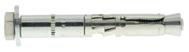
High security, high performance fixing for use in cracked and non-cracked concrete
TECHNICAL DATA
ANCHOR MECHANICAL PROPERTIES
RANGE Min. anchor depth Max. thick. of part to be fixed Min. thick. of base material Thread Ø Drilling depth Drilling Ø Clearance Ø Total anchor length Tighten torque Code (mm) (mm) (mm) (mm) (mm) (mm) (mm) (mm) (Nm) h ef t fix h min d h 0 d 0 df L T inst V6-10/10 50 10 100 M6 70 10 12 70 10 050694 V8-12/30 60 30 120 M8 80 12 14 100 25 050596 E8-12/45 45 124 050598 TF8-12/30 30 100 057902 V10-15/25 70 25 140 M10 90 15 17 115 50 050601 E10-15/45 45 139 050604 V12-18/25 80 25 160 M12 105 18 20 120 80 050605 E12-18/45 45 152 050608 E16-24/20 95 20 200 M16 130 24 26 157 170 052940 Tinst L hmin L h0 hef Tinst tfix d0 df d d ⁃ Safety critical loads ⁃ Overhead crane rails ⁃ Steel columns and walkways ⁃ Wall plates ⁃ Safety rails
SIZE M6 M8 M10 M12 M16 Type V Seq,V [mm2] Equivalent stressed cross-section bolt version 39,2 76,1 108,8 175,3 335,1 fuk [N/mm2] Min. tensile strength 800 800 800 800 800 fyk [N/mm2] Yield strength 600 600 600 600 600 M0Rk,s [mm2] Characteristic bending moment 12,2 30,0 59,8 104,8 266,4 M [mm2] Recommended bending moment 5,8 12,4 24,8 43,5 110,7 Type E Seq,E [mm2] Equivalent stressed cross-section threaded stud version 35,2 61,8 82,0 104,1 183,3 fuk [N/mm2] Min. tensile strength 700 700 700 700 700 fyk [N/mm2] Yield strength 350 350 350 350 350 M0Rk,s [mm2] Characteristic bending moment 10,6 26,2 52,3 91,7 233,1 M [mm2] Recommended bending moment 4,4 10,9 21,8 38,2 97,1 SW [mm] Key size 10 13 16 18 24
INSTALLATION APPLICATION CHARACTERISTICS STAINLESS STEEL
A4
25
TRIGA Z A4
TRIGA Z A4
MINIMUM THICKNESS OF CONCRETE, CHARATERISTIC & MINIMUM DISTANCES FOR SPACING, EDGE
CHARACTERISTIC RESISTANCES [kN]
Characteristic resistances are shown as informative, and have to be used by application of safety factors.
RECOMMENDED LOADS OF ONE ANCHOR WITHOUT INFLUENCE OF SPACING & CONCRETE EDGE [kN]
Recommended values are given for spacing ≥ Scr and edge distance ≥ Ccr
CONCRETE ‒ C20/25 to C50/60
TENSILE NON-CRACKED CONCRETE ‒ C20/25 SIZE M6 M8 M10 M12 M16 hef [mm] 50 60 70 80 100 Type V/E/TF NRk,p [kN] 17,4 16,0 20,0 25,0 50,0 CRACKED CONCRETE ‒ C20/25 SIZE M6 M8 M10 M12 M16 hef [mm] 50 60 70 80 100 Type V/E/TF NRk,p [kN] 5,0 9,0 16,0 24,6 34,4
SIZE M6 M8 M10 M12 M16 Anchorage depth hef [mm] 50 60 70 80 100 Minimum thickness of base material hmin [mm] 100 120 140 160 200 Characteristic edge and spacing distance for full anchor capacity Ccr ≥ [mm] 75 90 105 120 150 Scr ≥ [mm] 150 180 210 240 300 Minimum distances for cracked and non-cracked concrete Cmin [mm] 50 60 70 80 100 S ≥ [mm] 100 100 160 160 180 Smin [mm] 50 60 70 80 100 C ≥ [mm] 80 100 100 160 180 SHEAR CRACKED AND NON-CRACKED CONCRETE ‒ C20/25 to C50/60 SIZE M6 M8 M10 M12 M16 hef [mm] 50 60 70 80 100 Type V/TF VRk,s [kN] 21,5 31,4 49,1 60,1 89,4 Type E VRk,s [kN] 12,6 16,6 27,2 41,4 65,6 TENSILE NON-CRACKED CONCRETE ‒ C20/25 SIZE M6 M8 M10 M12 M16 hef [mm] 50 60 70 80 100 Type V/TF NRec [kN] 7,1 7,6 9,5 11,9 23,8 Type E NRec [kN] 4,8 7,6 9,5 11,9 23,8 CRACKED CONCRETE ‒ C20/25 SIZE M6 M8 M10 M12 M16 hef [mm] 50 60 70 80 100 Type V/E/TF NRec [kN] 2,4 4,3 7,6 11,7 16,4 NRec = min [NRd,p ; NRd,c; NRd,s] / γF ; γF = 1,4 SHEAR CRACKED AND NON-CRACKED
SIZE M6 M8 M10 M12 M16 hef [mm] 50 60 70 80 100 Type V/TF VRec [kN] 11,5 16,9 26,4 32,3 48,0 Type E VRec [kN] 4,5 5,9 9,7 14,8 37,5 VRec = VRd,s / γF ; γF = 1,4
Nota: The values indicated in italics and underlined correspond to steel failure
26
i-Expert Software
Design resistances for static loads are given for spacing ≥ Scr and edge distance ≥ Ccr For project with reduced spacing and edge distance, we recommend to use SPIT i-Expert software to design your project according to EN 1992-4.
DESIGN RESISTANCE FOR STATIC LOADS IN NON-CRACKED CONCRETE [kN]
DESIGN RESISTANCE FOR STATIC LOADS IN CRACKED CONCRETE [kN]
TENSILE SIZE M6 M8 M10 M12 M16 hef [mm] 50 60 70 80 100 Type V/TF NRd,uncr [kN] C20/25 10,0 10,7 13,3 16,7 33,3 C40/50 10,0 15,1 18,9 23,6 46,4 Type E NRd,uncr [kN] C20/25 6,7 10,7 13,3 16,7 33,3 C40/50 6,7 12,1 18,9 23,6 46,4 Distances Scr and Ccr must be fulfilled NRd,uncr = min[NRk,p,uncr / γMc ; NRk,s / γMs,N] γMc = 1,5 Type V/TF: γMs,N = 1,60 Type E: M6-M12 γMs,N = 2,40 ; M16 γMs,N = 1,50 SHEAR SIZE M6 M8 M10 M12 M16 hef [mm] 50 60 70 80 100 Type V/TF VRd,s [kN] ≥ C20/25 16,2 23,6 36,9 45,2 67,2 Type E VRd,s [kN] ≥ C20/25 6,3 8,3 13,6 20,7 52,5 VRd,s = VRk,s /γMs,V Type V/TF: γMs,V = 1,33 Type E: M6-M12 γMs,V = 2,00 ; M16 γMs,V = 1,25 TENSILE SIZE M6 M8 M10 M12 M16 hef [mm] 50 60 70 80 100 Type V/E/TF NRd,cr [kN] C20/25 3,3 6,0 10,7 16,4 23,0 C40/50 4,7 8,5 15,1 23,2 32,5 Distances Scr and Ccr must be fulfilled NRd,cr = min[NRk,p,cr / γMc ; NRk,s / γMs,N] γMc = 1,5 Type V/TF: γMs,N = 1,60 Type E: M6-M12 γMs,N = 2,40 ; M16 γMs,N = 1,50
SHEAR SIZE M6 M8 M10 M12 M16 hef [mm] 50 60 70 80 100 Type V/TF VRd,s [kN] ≥ C20/25 16,2 23,6 36,9 45,2 67,2 Type E VRd,s [kN] ≥ C20/25 6,3 8,3 13,6 20,7 52,5 VRd,s = VRk,s /γMs,V Type V/TF: γMs,V = 1,33 Type E: M6-M12 γMs,V = 2,00 ; M16 γMs,V = 1,25
Nota: The values indicated in italics and underlined correspond to steel failure
27
TRIGA Z A4
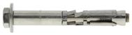
GUARDIA
ZINC COATED & STAINLESS STEEL A4
Mechanical anchor, dedicated for safety barriers fixings
CHARACTERISTICS ZINC COATED STEEL Zn STAINLESS STEEL
ETA - 07/0047 ETA ANCHOR MECHANICAL PROPERTIES SIZE 12X105/20 12X110/20 A4 Cone fuk [N/mm2] Min. tensile strength 1000 500 Body fuk [N/mm2] Min. tensile strength 550 700 Wel [mm3] Elastic section modulus 50 50 M0Rk,s [Nm] Characteristic bending moment 33 26 M [Nm] Recommended bending moment 13,7 10,8 SW [mm] Key size 16 13
A4
INSTALLATION ⁃ Safety barriers APPLICATION d0 hef tfix hmin h0 df L Tinst POSSIBLE 6 mm maxi. TECHNICAL DATA RANGE Min. anchor depth Max. thick. of part to be fixed Drilling depth Drilling diameter Min. thickness of base material Clearance diameter Total anchor length Tighten torque Code (mm) (mm) (mm) (mm) (mm) (mm) (mm) (Nm) h ef t fix h 0 d 0 h min df L T inst 12X105/20 70 20 95 12 150 14 104 35 051061 12X110/20 A4 70 20 100 12 150 14 110 25 055304
28
MINIMUM THICKNESS OF CONCRETE, CHARATERISTIC & MINIMUM DISTANCES FOR SPACING, EDGE
CHARACTERISTIC RESISTANCES [kN]
Characteristic resistances are shown as informative, and have to be used by application of safety factors.
RECOMMENDED LOADS OF ONE ANCHOR WITHOUT INFLUENCE OF SPACING & CONCRETE EDGE [kN]
Recommended values are determined from performances given in the ETA, and are guaranteed for spacing ≥ Scr and edge distance ≥ Ccr
Design resistances for static loads are determined from performances given in the ETA, and are guaranteed for spacing ≥ Scr and edge distance ≥ Ccr For project with reduced spacing and edge distance, we recommend to use SPIT i-Expert software to design your project according to EN 1992-4.
DESIGN RESISTANCE FOR STATIC LOADS IN NON CRACKED CONCRETE [kN]
SIZE 12X105/20 12X110/20 A4 Anchorage depth hef [mm] 70 70 Minimum thickness of base material hmin [mm] 150 150 Characteristic edge and spacing distance for full anchor capacity Ccr ≥ [mm] 105 105 Scr ≥ [mm] 210 210 Minimum distances for non-cracked concrete Smin [mm] 70 70 Cmin [mm] 50 50 TENSILE NON-CRACKED CONCRETE ‒ C20/25 SIZE 12X105/20 12X110/20 A4 hef [mm] 70 70 NRk,p [kN] 28,8 20,0
SHEAR NON-CRACKED CONCRETE ‒ C20/25 to C50/60 SIZE 12X105/20 12X110/20 A4 hef [mm] 70 70 VRk,s [kN] 14,3 12,8 TENSILE NON-CRACKED CONCRETE ‒ C20/25 SIZE 12X105/20 12X110/20 A4 hef [mm] 70 70 NRec [kN] 12,8 9,5 NRec = min [NRd,p ; NRd,c; NRd,s] / γF ; γF = 1,4
SHEAR NON-CRACKED CONCRETE ‒ C20/25 to C50/60 SIZE 12X105/20 12X110/20 A4 hef [mm] 70 70 VRec [kN] 6,8 5,9 VRec = VRd,s / γF ; γF = 1,4
TENSILE SIZE 12X105/20 12X110/20 A4 hef [mm] 70 70 NRd,uncr [kN] C20/25 17,9 13,3 C40/50 17,9 13,9 Distances Scr and Ccr must be fulfilled NRd,uncr = min[NRk,p,uncr / γMc ; NRk,s / γMs,N] γMc = 1,5 GUARDIA 12X105/20: γMs N = 1,4 GUARDIA 12X115/20 A4: γMs N = 1,87 SHEAR SIZE 12X105/20 12X110/20 A4 hef [mm] 70 70 VRd,s [kN] ≥ C20/25 9,5 8,2 VRd,s = VRk,s /γMs,V GUARDIA 12X105/20: γMs,V = 1,5 GUARDIA 12X115/20 A4: γMs,V = 1,56
i-Expert Software Nota: The values indicated in italics and underlined correspond to steel failure ZINC COATED & STAINLESS STEEL A4 GUARDIA 29
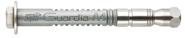
FIX Z XTREM
TECHNICAL DATA
RANGE Letter marking Maximum anchorage depth Minimum anchorage depth Thread Ø Drilling Ø Clearance Ø Total anchor length Tighten torque Code Max. anchor depth Embed. depth Max. thick. of part to be fixed Drilling depth Min. thick. of base material Min. anchor depth Embed. depth Max. thick. of part to be fixed Drilling depth Min. thick. of base material (mm) (mm) (mm) (mm) (mm) (mm) (mm) (mm) (mm) (mm) (mm) (mm) (mm) (mm) (Nm) h ef h nom t fix h 0 h min h ef h nom t fix h 0 h min d d 0 df L T inst 8X65/5 B 46 55 5 65 100 - - - - 8 8 9 65 20 057763 8X75/15 D 15 75 057764 8X90/30 E 30 - 90 057765 8X120/60 G 60 120 057766 10X85/25-5 D 60 68 5 75 120 40 48 25 55 100 10 10 12 85 45 057768 10X90/30-10 E 10 30 90 057769 10X100/40-20 F 20 40 100 057770 10X120/60-40 G 40 60 120 057771 10X140/80-60 I 60 80 140 057772 10X160/100-80 - 80 100 160 057773 12X105/30-10 F 70 80 10 90 140 50 60 30 70 100 12 12 14 105 60 057775 12X115/40-20 G 20 40 115 057776 12X135/60-40 I 40 60 135 057777 12X155/80-60 J 60 80 155 057796 12X180/105-85 L 85 105 180 057779 16X145/45-25 I 85 98 25 110 170 65 78 45 90 130 16 16 18 145 110 057781 16X170/70-50 K 50 70 170 057782 16X180/80-60 L 60 80 180 057783 20X170/30 K 100 113 30 130 200 - - - - 20 20 22 170 160 057785 20X200/60 M 60 - 200 057786 20X220/80 O 80 220 057787 Large Washer (LW) 8X65/5 B 46 55 5 65 100 - - - - - 8 8 9 65 20 057666 8X130/70 I 70 130 057667 10X160/100-80 J 60 68 80 75 120 40 48 100 55 100 10 10 12 160 45 057668 12X135/60-40 I 70 80 40 90 140 50 60 60 70 100 12 12 14 135 60 057669 12X155/80-60 J 60 80 155 057670 12X180/105-85 L 85 105 180 057671 12X220/123* O 123 - - - - - 220 057672 12X255/158* R 158 - - - - - 255 057673 16X180/80-60 L 85 98 60 105 170 65 78 80 105 170 16 16 18 180 110 057675 16X220/100* O 100 - - - - - 220 100 057676 16X250/130* Q 130 - - - - - 250 100 057677 d0 hef tfix hmin h0 df L d hnom Tinst ETA - 15/0388 * ETA - 17/0073 ETA
INSTALLATION ⁃ Steel and timber framework and beams ⁃ Lift guide rails ⁃ Industrial doors and gates ⁃ Brickwork support angles ⁃ Storage systems ⁃ Wall plates ⁃ Safety barriers ⁃ Cladding brackets ⁃ Curtain-walls APPLICATION ANCHOR MECHANICAL PROPERTIES SIZE M8 M10 M12 M12 L>220 M16 M16 L>220 M20 Cross-section above cone fuk [N/mm2] Min. tensile strength 900 830 830 830 720 720 600 fyk [N/mm2] Yield strength 800 670 670 670 580 580 580 As [mm2] Stressed cross-section 22,9 35,3 45,4 45,4 88,2 88,2 165,1 Threaded part fuk [N/mm2] Min. tensile strength 750 730 730 730 600 600 500 fyk [N/mm2] Yield strength 680 580 580 580 480 480 410 As [mm2] Stressed cross-section 36,6 58,0 84,3 84,3 156,0 156,0 245,0 Wel [mm3] Elastic section modulus 31,2 62,3 109,2 109,2 277,5 277,5 540,9 M0Rk,s [Nm] Characteristic bending moment 28,0 52,8 91,3 78,6 194,0 199,8 315,7 M [Nm] Recommended bending moment 8,7 14,7 25,8 22,4 54,4 57,0 90,5 SW [mm] Key size 13 17 19 19 24 24 30 Washer Standard (NF E 25513) Large (DIN 440 / ISO 7094) SIZE M8 M10 M12 M16 M20 M8 M10 M12 M16 Outer Ø [mm] 16 20 24 30 36 28 34 44 56 Thickness [mm] 1,6 2 2,5 3 3 3 3 4 5 ZINC COATED STEEL Zn CHARACTERISTICS Vds CEA 4001 M8 - M12
Torque controlled expansion anchor, for use in cracked and non-cracked concrete and seismic performance categories C1 & C2
30
MINIMUM THICKNESS OF CONCRETE, CHARATERISTIC & MINIMUM DISTANCES FOR SPACING, EDGE
CHARACTERISTIC RESISTANCES [kN]
Characteristic resistances are shown as informative, and have to be used by application of safety factors.
SHEAR
RECOMMENDED LOADS OF ONE ANCHOR WITHOUT INFLUENCE OF SPACING & CONCRETE EDGE [kN]
Recommended values are determined from performances given in the ETA, and are guaranteed for spacing ≥ Scr and edge distance ≥ Ccr
SIZE M8 M10 M10 M12 M12 M16 M16 M20 Anchorage depth hef [mm] 46 40 60 50 70 65 85 100 Minimum thickness of base material hmin [mm] 100 100 120 100 140 130 170 200 Characteristic edge and spacing distance for full anchor capacity Ccr ≥ [mm] 69 60 90 75 105 97,5 127,5 150 Scr ≥ [mm] 138 120 180 150 210 195 255 300 Minimum distances for non-cracked concrete Cmin [mm] 50 60 60 60 60 90 90 100 S ≥ [mm] 75 120 120 145 145 140 140 160 Smin [mm] 50 55 55 60 60 90 90 130 C ≥ [mm] 90 70 70 100 100 105 105 120 Minimum distances for cracked concrete Cmin [mm] 50 55 55 60 60 80 80 100 S ≥ [mm] 75 90 90 145 145 110 110 130 Smin [mm] 50 55 55 60 60 90 90 100 C ≥ [mm] 65 70 70 100 100 100 100 120
Nota: The values indicated in italics and underlined correspond to steel failure
TENSILE NON-CRACKED CONCRETE ‒ C20/25 SIZE M8 M10 M12 M12 L>220 M16 M16 L>220 M20 hef,1 [mm] 46 60 70 70 85 85 100 NRk,p [kN] 9,0 20,0 30,0 20,0 40,0 35,0 49,2 hef,2 [mm] - 40 50 - 65 -NRk,p [kN] - 12,4 17,4 - 25,8 -CRACKED CONCRETE ‒ C20/25 SIZE M8 M10 M12 M12 L>220 M16 M16 L>220 M20 hef,1 [mm] 46 60 70 70 85 85 100 NRk,p [kN] 5,0 9,0 16,0 12,0 20,0 25,0 30,0 hef,2 [mm] - 40 50 - 65 -NRk,p [kN] - 8,7 12,2 - 18,0 - -
CRACKED AND NON-CRACKED CONCRETE ‒ C20/25 to C50/60 SIZE M8 M10 M12 M12 L>220 M16 M16 L>220 M20 hef,1 [mm] 46 60 70 70 85 85 100 hef,2 [mm] - 40 50 - 65 -VRk,s [kN] 13,7 16,0 23,0 25,3 45,0 47,1 61,0 TENSILE NON-CRACKED CONCRETE ‒ C20/25 SIZE M8 M10 M12 M12 L>220 M16 M16 L>220 M20 hef,1 [mm] 46 60 70 70 85 85 100 NRec [kN] 4,3 9,5 14,3 9,5 19,0 16,6 23,4 hef,2 [mm] - 40 50 - 65 -NRec [kN] - 5,9 8,3 - 12,3 -CRACKED CONCRETE ‒ C20/25 SIZE M8 M10 M12 M12 L>220 M16 M16 L>220 M20 hef,1 [mm] 46 60 70 70 85 85 100 NRec [kN] 2,4 4,3 7,6 5,7 9,5 12,0 14,3 hef,2 [mm] - 40 50 - 65 -NRec [kN] - 4,1 5,8 - 8,6 -NRec = min [NRd,p ; NRd,c; NRd,s] / γF ; γF = 1,4
CRACKED AND NON-CRACKED CONCRETE ‒ C20/25 to C50/60 SIZE M8 M10 M12 M12 L>220 M16 M16 L>220 M20 hef,1 [mm] 46 60 70 70 85 85 100 hef,2 [mm] - 40 50 - 65 -VRec [kN] 6,5 9,0 12,9 14,4 25,7 26,9 29,0 VRec = VRd,s / γF ; γF = 1,4
XTREM 31
SHEAR
FIX Z
FIX Z XTREM
Design resistances for static, seismic and fire loads are determined from performances given in the ETA, and are guaranteed for spacing ≥ Scr and edge distance ≥ Ccr. For project with reduced spacing and edge distance, we recommend to use SPIT i-Expert software to design your project according to EN 1992-4.
DESIGN RESISTANCE FOR STATIC LOADS IN NON CRACKED CONCRETE [kN]
DESIGN RESISTANCE FOR STATIC LOADS IN CRACKED CONCRETE [kN]
DESIGN RESISTANCE FOR SEISMIC LOADS CATEGORY C1 [kN]
DESIGN RESISTANCE FOR SEISMIC LOADS CATEGORY C2 [kN]
DESIGN RESISTANCE FOR FIRE
[kN]
Nota: The values indicated in italics and underlined correspond to steel failure
TENSILE SIZE M8 M10 M12 M12 L>220 M16 M16 L>220 M20 hef,1 [mm] 46 60 70 70 85 85 100 NRd,uncr [kN] C20/25 6,0 13,3 20,0 13,3 26,7 23,3 32,8 C40/50 8,5 15,3 23,0 18,8 34,0 32,9 46,4 hef,2 [mm] - 40 50 - 65 -NRd,uncr [kN] C20/25 - 8,3 11,6 - 17,2 -C40/50 - 9,5 13,3 - 21,9 -Distances Scr and Ccr must be fulfilled NRd,uncr = min[NRk,p,uncr / γMc ; NRk,s / γMs,N] γMc = 1,5 ; M8 : γMs,N = 1,4 ; M10-M16 : γMs,N = 1,48 ; M20 : γMs,N = 1,5 SHEAR SIZE M8 M10 M12 M12 L>220 M16 M16 L>220 M20 hef,1 [mm] 46 60 70 70 85 85 100 hef,2 [mm] - 40 50 - 65 -VRd,s [kN] ≥ C20/25 9,1 12,6 18,1 20,2 36,0 37,7 40,7 VRd,s = VRk,s /γMs,V M8 : γMs,V = 1,5 ; M10-M16 : γMs,V = 1,27 ; M20 : γMs,V = 1,5; M12-M16 L>220 : γMs,V = 1,25
TENSILE SIZE M8 M10 M12 M12 L>220 M16 M16 L>220 M20 hef,1 [mm] 46 60 70 70 85 85 100 NRd,C1 [kN] C20/25 3,1 4,9 10,7 5,6 13,3 11,7 20,0 C40/50 4,4 7,0 15,1 7,9 18,9 16,5 28,3 Distances Scr and Ccr must be fulfilled NRd,C1 = min[NRk,p,eq,C1 / γMc ; NRk,s,eq,C1 / γMs,N] γMc = 1,5 ; M8 : γMs,N = 1,4 ; M10-M16 : γMs,N = 1,48 ; M20 : γMs,N = 1,5 SHEAR SIZE M8 M10 M12 M12 L>220 M16 M16 L>220 M20 hef,1 [mm] 46 60 70 70 85 85 100 VRd,s,C1 [kN] ≥ C20/25 4,0 12,6 18,1 14,2 36,0 26,4 40,7 VRd,s,C1 = VRk,s,eq,C1 / γMs,V M8 : γMs,V = 1,5 ; M10-M16 : γMs,V = 1,27 ; M20 : γMs,V = 1,5 M12-M16 L>220 : γMs,V = 1,25 TENSILE SIZE M8 M10 M12 M12 L>220 M16 M16 L>220 M20 hef,1 [mm] 46 60 70 70 85 85 100 NRd,cr [kN] C20/25 3,3 6,0 10,7 8,0 13,3 16,7 20,0 C40/50 4,7 6,9 12,3 11,3 17,0 23,5 28,3 hef,2 [mm] - 40 50 - 65 -NRd,cr [kN] C20/25 - 5,8 8,1 - 12,0 -C40/50 - 6,7 9,3 - 15,3 -Distances Scr and Ccr must be fulfilled NRd,cr = min[NRk,p,cr / γMc ; NRk,s / γMs,N] γMc = 1,5 ; M8 : γMs,N = 1,4 ; M10-M16 : γMs,N = 1,48 ; M20 : γMs,N = 1,5 SHEAR SIZE M8 M10 M12 M12 L>220 M16 M16 L>220 M20 hef,1 [mm] 46 60 70 70 85 85 100 hef,2 [mm] - 40 50 - 65 -VRd,s [kN] ≥ C20/25 9,1 12,6 18,1 20,2 36,0 37,7 40,7 VRd,s = VRk,s / γMs,V M8 : γMs,V = 1,5 ; M10-M16 : γMs,V = 1,27 ; M20 : γMs,V = 1,5 M12-M16 L>220 : γMs,V = 1,25
TENSILE SIZE M8 M10 M12 M12 L>220 M16 M16 L>220 M20 hef,1 [mm] 46 60 70 70 85 85 100 NRd,C2 [kN] C20/25 - 1,9 4,0 3,5 12,0 5,9 17,1 C40/50 - 2,1 4,6 4,9 15,3 8,4 24,1 Distances Scr and Ccr must be fulfilled NRd,C2 = min[NRk,p,eq,C2 / γMc ; NRk,s,eq,C2 / γMs,N] γMc = 1,5 ; M8 : γMs,N = 1,4 ; M10-M16 : γMs,N = 1,48 ; M20 : γMs,N = 1,5 SHEAR SIZE M8 M10 M12 M12 L>220 M16 M16 L>220 M20 hef,1 [mm] 46 60 70 70 85 85 100 VRd,s,C2 [kN] ≥ C20/25 - 7,6 11,0 14,2 27,1 26,4 29,8 VRd,s,C2 = VRk,s,eq,C2 /γMs,V M8 : γMs,V = 1,5 ; M10-M16 : γMs,V = 1,27 ; M20 : γMs,V = 1,5 M12-M16 L>220 : γMs,V = 1,25
EXPOSURE
TENSILE SIZE M8 M10 M12 M12 L>220 M16 M16 L>220 M20 hef,1 [mm] 46 60 70 70 85 85 100 NRd,fi R30 [kN] 0,9 2,8 3,6 1,7 6,6 3,1 10,4 NRd,fi R60 [kN] 0,7 2,3 3,1 1,3 5,7 2,4 9,0 NRd,fi R90 [kN] 0,5 1,8 2,6 1,1 4,9 2,0 7,6 NRd,fi R120 [kN] 0,4 1,6 2,4 0,8 4,4 1,6 6,9 NRd,fi = NRk,s,fi /γM,fi γM,fi = 1,0 SHEAR SIZE M8 M10 M12 M12 L>220 M16 M16 L>220 M20 hef,1 [mm] 46 60 70 70 85 85 100 VRd,fi R30 [kN] 0,9 2,8 3,6 1,7 6,6 3,1 10,4 VRd,fi R60 [kN] 0,7 2,3 3,1 1,3 5,7 2,4 9,0 VRd,fi R90 [kN] 0,5 1,8 2,6 1,1 4,9 2,0 7,6 VRd,fi R120 [kN] 0,4 1,6 2,4 0,8 4,4 1,6 6,9 VRd,fi = VRk,s,fi /γM,fi γM,fi = 1,0
i-Expert Software
32
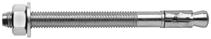
Torque controlled expansion anchor, for use in cracked and non-cracked concrete and seismic performance categories C1 & C2
CHARACTERISTICS
A4
TECHNICAL DATA RANGE marking Maximum anchorage depth Minimum anchorage depth Thread Ø Drilling Ø Clearance Ø Total anchor length Tighten torque Code Max. anchor depth Embed. depth Max. thick. of part to be fixed Drilling depth Min. thick. of base material Min. anchor depth Embed. depth Max. thick. of part to be fixed Drilling depth Min. thick. of base material (mm) (mm) (mm) (mm) (mm) (mm) (mm) (mm) (mm) (mm) (mm) (mm) (mm) (mm) (Nm) h ef h nom t fix h 0 h min h ef h nom t fix h 0 h min d d 0 df L T inst 8X55/5 0 4 8 5565 100 35 42 5 52 100 8 8 9 56 20 058616 8X70/20-7 1 7 20 71 058617 8X90/40 -27 3 27 40 91 058618 10X70/10 1 60 6875 120 40 48 10 55 100 10 10 12 70 45 058619 10X95/35-15 2 15 35 95 058620 10X105/45-25 3 25 4 5 105 058621 10X130/70-50 4 50 70 130 058622 12X95/20 1 70 8090 140 50 60 20 70 100 12 12 14 95 75 058623 12X110/35-15 2 15 35 110 058624 12X120/45-25 3 25 45 120 058625 12X140/65-45 4 45 65 140 058626 16X120/20 1 85 98110 170 65 78 20 90 130 16 16 18 120 110 058627 16X140/40-20 2 20 40 140 058628 d0 hef tfix hmin h0 df L d hnom Tinst ⁃ Safety barriers ⁃ Cladding brackets ⁃ Curtain-walls ⁃ Steel and timber framework and beams ⁃ Lift guide rails ⁃ Industrial doors and gates ⁃ Brickwork support angles ⁃ Storage systems ETA - 15/0388 ETA ANCHOR MECHANICAL PROPERTIES SIZE M8 M10 M12 M16 Cross-section above cone fuk [N/mm2] Min. tensile strength 900 830 720 720 fyk [N/mm2] Yield strength 800 670 580 580 As [mm2] Stressed cross-section 22,9 35,3 52,8 103,8 Threaded part fuk [N/mm2] Min. tensile strength 750 730 730 600 fyk [N/mm2] Yield strength 680 580 580 480 As [mm2] Stressed cross-section 36,6 58,0 84,3 156,0 Wel [mm3] Elastic section modulus 31,2 62,3 109,2 277,5 M0Rk,s [Nm] Characteristic bending moment 25,0 44,9 77,5 187,5 M [Nm] Recommended bending moment 10,0 18,0 31,0 75,0 SW [mm] Key size 13 17 19 24 INSTALLATION APPLICATION STAINLESS STEEL
Vds CEA 4001 M8 - M12
33
FIX Z XTREM a4
MINIMUM THICKNESS OF CONCRETE, CHARATERISTIC & MINIMUM DISTANCES FOR SPACING, EDGE
CHARACTERISTIC RESISTANCES [kN]
Characteristic resistances are shown as informative, and have to be used by application of safety factors.
RECOMMENDED LOADS OF ONE ANCHOR WITHOUT INFLUENCE OF SPACING & CONCRETE EDGE [kN]
Recommended values are determined from performances given in the ETA, and are guaranteed for spacing ≥ Scr and edge distance ≥ Ccr
SHEAR
SIZE M8 M10 M10 M12 M12 M16 M16 Anchorage depth hef [mm] 48 40 60 50 70 65 85 Minimum thickness of base material hmin [mm] 100 100 120 100 140 130 170 Characteristic edge and spacing distance for full anchor capacity Ccr ≥ [mm] 72 60 90 75 105 97,5 127,5 Scr ≥ [mm] 144 120 180 150 210 195 255 Minimum distances for non-cracked concrete Cmin [mm] 60 60 60 60 60 90 90 S ≥ [mm] 50 120 120 100 145 105 140 Smin [mm] 50 55 55 60 60 90 90 C ≥ [mm] 60 65 65 100 100 105 105 Minimum distances for cracked concrete Cmin [mm] 60 55 55 60 60 80 80 S ≥ [mm] 60 90 90 145 145 110 110 Smin [mm] 60 55 55 60 60 90 90 C ≥ [mm] 60 65 65 100 100 100 100 TENSILE NON-CRACKED CONCRETE ‒ C20/25 SIZE M8 M10 M12 M16 hef,1 [mm] 35 40 50 65 NRec [kN] 4,3 5,9 8,3 12,3 hef,2 [mm] 48 60 70 85 NRec [kN] 5,7 9,5 14,3 19,0 CRACKED CONCRETE ‒ C20/25 SIZE M8 M10 M12 M16 hef,1 [mm] 35 40 50 65 NRec [kN] 1,4 4,1 5,8 8,6 hef,2 [mm] 48 60 70 85 NRec [kN] 1,9 4,3 7,6 9,5 NRec = min [NRd,p ; NRd,c; NRd,s] / γF ; γF = 1,4
CRACKED AND NON-CRACKED CONCRETE ‒ C20/25 to C50/60 SIZE M8 M10 M12 M16 hef,1 [mm] 35 40 50 65 hef,2 [mm] 48 60 70 85 VRec [kN] 8,2 12,7 19,2 29,7 VRec = VRd,s / γF ; γF = 1,4 TENSILE NON-CRACKED CONCRETE ‒ C20/25 SIZE M8 M10 M12 M16 hef,1 [mm] 35 40 50 65 NRk,p [kN] 9,0 12,4 17,4 25,8 hef,2 [mm] 48 60 70 85 NRk,p [kN] 12,0 20,0 30,0 40,0 CRACKED CONCRETE ‒ C20/25 SIZE M8 M10 M12 M16 hef,1 [mm] 35 40 50 65 NRk,p [kN] 3,0 8,7 12,2 18,0 hef,2 [mm] 48 60 70 85 NRk,p [kN] 4,0 9,0 16,0 20,0 SHEAR CRACKED AND NON-CRACKED CONCRETE ‒ C20/25 to C50/60 SIZE M8 M10 M12 M16 hef,1 [mm] 35 40 50 65 hef,2 [mm] 48 60 70 85 VRk,s [kN] 12,4 18,7 28,2 51,9
Nota: The values indicated in italics and underlined correspond to steel failure
34
FIX Z XTREM a4
FIX Z XTREM a4
Design resistances for static, seismic and fire loads are determined from performances given in the ETA, and are guaranteed for spacing ≥ Scr and edge distance ≥ Ccr. For project with reduced spacing and edge distance, we recommend to use SPIT i-Expert software to design your project according to EN 1992-4.
DESIGN RESISTANCE FOR STATIC LOADS IN NON CRACKED CONCRETE [kN]
DESIGN RESISTANCE FOR STATIC LOADS IN CRACKED CONCRETE [kN]
DESIGN RESISTANCE FOR SEISMIC LOADS CATEGORY C1 [kN]
DESIGN
TENSILE SIZE M8 M10 M12 M16 hef,1 [mm] 35 40 50 65 NRd,uncr [kN] C20/25 6,0 8,3 11,6 17,2 C40/50 8,5 9,5 13,3 21,8 hef,2 [mm] 48 60 70 85 NRd,uncr [kN] C20/25 8,0 13,3 20,0 26,7 C40/50 9,2 15,3 22,1 32,6 Distances Scr and Ccr must be fulfilled NRd,uncr = min[NRk,p,uncr / γMc ; NRk,s / γMs,N] γMc = 1,5 ; M8 : γMs,N = 1,4 ; M10-M16 : γMs,N = 1,48 ; M20 : γMs,N = 1,5 SHEAR SIZE M8 M10 M12 M16 hef,1 [mm] 35 40 50 65 hef,2 [mm] 48 60 70 85 VRd,s [kN] ≥ C20/25 8,2 12,7 19,2 29,7 VRd,s = VRk,s /γMs,V M8 : γMs,V = 1,5 ; M10-M16 : γMs,V = 1,27 ; M20 : γMs,V = 1,5
TENSILE SIZE M8 M10 M12 M16 hef,2 [mm] 48 60 70 85 NRd,C1 [kN] C20/25 2,7 4,9 10,7 13,3 C40/50 3,8 5,7 12,3 16,9 Distances Scr and Ccr must be fulfilled NRd,C1 = min[NRk,p,eq,C1 / γMc ; NRk,s,eq,C1 / γMs,N] γMc = 1,5 ; M8 : γMs,N = 1,4 ; M10-M16 : γMs,N = 1,48 ; M20 : γMs,N = 1,5 SHEAR SIZE M8 M10 M12 M16 hef,2 [mm] 48 60 70 85 VRd,s,C1 [kN] ≥ C20/25 3,8 8,3 12,1 19,3 VRd,s,C1 = VRk,s,eq,C1 / γMs,V M8 : γMs,V = 1,5 ; M10-M16 : γMs,V = 1,27 ; M20 : γMs,V = 1,5 TENSILE SIZE M8 M10 M12 M16 hef,1 [mm] 60 55 60 80 NRd,cr [kN] C20/25 2,0 5,8 8,1 12,0 C40/50 2,8 6,7 9,3 15,2 hef,2 [mm] 48 60 70 85 NRd,cr [kN] C20/25 2,7 6,0 10,7 13,3 C40/50 3,8 6,9 12,3 16,9 Distances Scr and Ccr must be fulfilled NRd,cr = min[NRk,p,cr / γMc ; NRk,s / γMs,N] γMc = 1,5 ; M8 : γMs,N = 1,4 ; M10-M16 : γMs,N = 1,48 ; M20 : γMs,N = 1,5 SHEAR SIZE M8 M10 M12 M16 hef,1 [mm] 35 40 50 65 hef,2 [mm] 48 60 70 85 VRd,s [kN] ≥ C20/25 8,2 12,7 19,2 29,7 VRd,s = VRk,s / γMs,V M8 : γMs,V = 1,5 ; M10-M16 : γMs,V = 1,27 ; M20 : γMs,V = 1,5
TENSILE SIZE M8 M10 M12 M16 hef,2 [mm] 48 60 70 85 NRd,C2 [kN] C20/25 - 1,7 4,0 9,7 C40/50 - 2,0 4,6 12,4 Distances Scr and Ccr must be fulfilled NRd,C2 = min[NRk,p,eq,C2 / γMc ; NRk,s,eq,C2 / γMs,N] γMc = 1,5 ; M8 : γMs,N = 1,4 ; M10-M16 : γMs,N = 1,48 ; M20 : γMs,N = 1,5 SHEAR SIZE M8 M10 M12 M16 hef,2 [mm] 48 60 70 85 VRd,s,C2 [kN] ≥ C20/25 - 5,0 7,3 14,5 VRd,s,C2 = VRk,s,eq,C2 /γMs,V M8 : γMs,V = 1,5 ; M10-M16 : γMs,V = 1,27 ; M20 : γMs,V = 1,5
RESISTANCE FOR SEISMIC LOADS CATEGORY C2 [kN]
FOR FIRE EXPOSURE [kN] TENSILE SIZE M8 M10 M12 M16 hef,2 [mm] 48 60 70 85 NRd,fi R30 [kN] 4,9 9,9 9,2 16,1 NRd,fi R60 [kN] 3,2 6,3 6,5 11,3 NRd,fi R90 [kN] 1,5 2,6 3,7 6,5 NRd,fi R120 [kN] 0,7 0,8 2,3 4,1 NRd,fi = NRk,s,fi /γM,fi γM,fi = 1,0 SHEAR SIZE M8 M10 M12 M16 hef,2 [mm] 48 60 70 85 VRd,fi R30 [kN] 4,9 9,9 9,2 16,1 VRd,fi R60 [kN] 3,2 6,3 6,5 11,3 VRd,fi R90 [kN] 1,5 2,6 3,7 6,5 VRd,fi R120 [kN] 0,7 0,8 2,3 4,1 VRd,fi = VRk,s,fi /γM,fi γM,fi = 1,0
DESIGN RESISTANCE
i-Expert Software Nota: The values indicated in italics and underlined correspond to steel failure
35
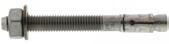
Torque controlled expansion anchor, for use in non-cracked concrete
TECHNICAL DATA
PROPERTIES
RANGE Letter marking Maximum anchorage depth Minimum anchorage depth Thread Ø Drilling Ø Clearance Ø Total anchor length Tighten torque Code Max anchor depth Embed. depth Max. thick. of part to be fixed Drilling depth Min. thick. of base material Min anchor depth Embed. depth Max. thick. of part to be fixed Drilling depth Min. thick. of base material (mm) (mm) (mm) (mm) (mm) (mm) (mm) (mm) (mm) (mm) (mm) (mm) (mm) (mm) (Nm) h ef h nom t fix h 0 h min h ef h nom t fix h 0 h min d d 0 df L T inst 6X45/5*35 4551 100 25,6 35 5 41 100 6 6 8 45 10 050510 6X55/15* - 5 15 55 050520 6X85/45* - 35 45 85 050530 8X55/540 4860 80 30 38 5 50 80 8 8 9 55 15 057450 8X70/20-10 C 10 20 70 057451 8X90/40-30 E 30 40 90 057452 8X100/50-40 F 40 50 100 057453 8X115/65-55 G 55 65 115 057454 8X130/80-70 H 70 80 130 057455 8X160/110-100 J 100 110 160 057456 10X65/550 6070 100 40 50 5 60 100 10 10 12 65 30 057460 10X75/15-5 C 5 15 75 057461 10X85/25-15 D 15 25 85 057462 10X95/36-26 E 26 36 95 057463 10X110/50-40 F 40 50 110 057464 10X125/65-55 G 55 65 125 057465 10X140/80-70 I 70 80 140 057466 10X160/100-90 J 90 100 160 057467 12X80/565 7790 130 50 62 5 75 100 12 12 14 80 50 057470 12X100/25-10 F 10 25 100 057471 12x115/40-25 G 25 40 115 057472 12x125/50-35 H 35 50 125 057473 12X140/65-50 I 50 65 140 057474 12X160/85-70 J 70 85 160 057664 12X180/105-90 L 90 105 180 057576 12X220/145-130 O 130 145 220 057477 16X100/580 95110 160 65 80 5 95 130 16 16 18 100 100 057480 16X125/30-15 G 15 30 125 057481 16X150/55-40 I 40 55 150 057482 16X170/75-60 K 60 75 170 057483 16X185/90-75 L 75 90 185 057484 16X235/140-125* - 125 140 235 057485 20X150/10 - - 10 150 057490 20X170/30 K - - - - - 100 113 30 130 200 20 20 22 170 160 057491 20X220/80 0 - 80 220 057492 Large Washer (LW) 12X300/200 * - 70 80 200 90 140 - - - - - 12 12 14 300 60 057673 16X300/205 -190* - 85 98 205 110 170 65 78 190 90 130 16 16 18 300 110 057675 * Do not belong to ETA d0 hef tfix hmin h0 df L d hnom Tinst ETA - 13/0005 ETA ANCHOR
SIZE M6 M8 M10 M12 M16 M20 Cross-section above cone fuk [N/mm2] Min. tensile strength 700 750 750 750 700 600 fyk [N/mm2] Yield strength 580 600 600 600 570 580 As [mm2] Stressed cross-section - 23,8 34,7 56,1 103,9 165,1 Threaded part fuk [N/mm2] Min. tensile strength 600 650 650 650 600 500 fyk [N/mm2] Yield strength 420 420 420 420 480 410 As [mm2] Stressed cross-section 20,1 36,6 58 84,3 157 245 Wel [mm3] Elastic section modulus 12,7 31,2 62,3 109,2 277,5 540,9 M0Rk,s [Nm] Characteristic bending moment 9 24 49 85 200 315,7 M [Nm] Recommended bending moment 3,7 9,8 20,0 34,7 81,6 90,5 SW [mm] Key size 10 13 17 19 24 30
MECHANICAL
INSTALLATION ⁃ Steel and timber framework and beams ⁃ Lift guide rails ⁃ Industrial doors and gates ⁃ Brickwork support angles ⁃ Storage systems APPLICATION Washer Standard (NF E 25513) Large (DIN 440 / ISO 7094) SIZE M8 M10 M12 M16 M20 M12 M16 Outer Ø [mm] 16 20 24 30 37 44 56 Thickness [mm] 1,6 2,0 2,5 3,0 3,0 4,0 5,0 ZINC COATED STEEL
FIX3 36
Zn CHARACTERISTICS
MINIMUM THICKNESS OF CONCRETE, CHARATERISTIC & MINIMUM DISTANCES FOR SPACING, EDGE
CHARACTERISTIC RESISTANCES [kN]
Characteristic resistances are shown as informative, and have to be used by application of safety factors.
RECOMMENDED LOADS OF ONE ANCHOR WITHOUT INFLUENCE OF SPACING & CONCRETE
values are determined from performances given in the ETA, and are guaranteed for spacing ≥ Scr and edge distance ≥
SHEAR
EDGE [kN]
NON-CRACKED CONCRETE ‒ C20/25 to C50/60
Design resistances for static loads are determined from performances given in the ETA, and are guaranteed for spacing ≥ Scr and edge distance ≥ Ccr For project with reduced spacing and edge distance, we recommend to use SPIT i-Expert software to design your project according to EN 1992-4.
DESIGN RESISTANCE FOR STATIC LOADS IN NON CRACKED CONCRETE [kN]
SIZE M8 M10 M10 M12 M12 M16 M16 M20 Anchorage depth hef [mm] 40 40 50 50 65 65 80 100 Minimum thickness of base material hmin [mm] 100 100 100 100 130 130 160 200 Characteristic edge and spacing distance for full anchor capacity Ccr ≥ [mm] 60 60 75 75 97,5 97,5 120 150 Scr ≥ [mm] 120 120 150 150 195 195 240 300 Minimum distances for non-cracked concrete Smin [mm] 45 50 60 100 70 100 90 130 Cmin [mm] 55 65 65 100 70 100 105 120 TENSILE NON-CRACKED CONCRETE ‒ C20/25 SIZE M6 M8 M10 M12 M16 M20 hef,1 [mm] 25 30 40 50 65NRk,p [kN] 5,7 7,5 12,4 17,4 25,8hef,2 [mm] 35 40 50 65 80 100 NRk,p [kN] 5,7 12,4 17,4 25,8 35,2 49,2
SHEAR NON-CRACKED CONCRETE ‒ C20/25 to C50/60 SIZE M6 M8 M10 M12 M16 M20 hef,1 [mm] 25 30 40 50 65hef,2 [mm] 35 40 50 65 80 100 VRk,s [kN] 3,6 10,0 13,7 27,4 36,5 61,0 TENSILE NON-CRACKED CONCRETE ‒ C20/25 SIZE M6 M8 M10 M12 M16 M20 hef,1 [mm] 25 30 40 50 65NRec [kN] 1,7 3,6 5,9 8,3 12,3hef,2 [mm] 35 40 50 65 80 100 NRec [kN] 2,7 5,9 8,3 12,3 16,8 23,4 NRec = min [NRd,p ; NRd,c; NRd,s] / γF ; γF = 1,4
Recommended
Ccr
SIZE M6 M8 M10 M12 M16 M20 hef,1 [mm] 25 30 40 50 65hef,2 [mm] 35 40 50 65 80 100 VRec [kN] 1,7 5,7 7,8 15,7 20,9 29,0 VRec = VRd,s / γF ; γF = 1,4
TENSILE SIZE M6 M8 M10 M12 M16 M20 hef,1 [mm] 25 30 40 50 65NRd,uncr [kN] C20/25 2,4 5,0 8,3 11,6 17,2C40/50 2,4 7,1 11,7 16,4 24,3hef,2 [mm] 35 40 50 65 80 100 NRd,uncr [kN] C20/25 3,8 8,3 11,6 17,2 23,5 32,8 C40/50 3,8 11,7 16,4 24,3 33,2 46,4 Distances Scr and Ccr must be fulfilled NRd,uncr = min[NRk,p,uncr / γMc ; NRk,s / γMs,N] γMc = 1,5 ; M8-M12 : γMs,N = 1,5 ; M16 : γMs,N = 1,47 ; M20 : γMs,N = 1,5 SHEAR SIZE M6 M8 M10 M12 M16 M20 hef,1 [mm] 25 30 40 50 65hef,2 [mm] 35 40 50 65 80 100 VRd,s [kN] 2,4 8,0 11,0 21,9 29,2 40,7 VRd,s = VRk,s /γMs,V M8-M16 : γMs,V = 1,25 ; M20 : γMs,V = 1,5
i-Expert Software Nota: The values indicated in italics and underlined correspond to steel failure FIX3 37
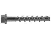
Concrete screw anchor for use in cracked and non-cracked concrete and seismic performance categories C1 & C2
TECHNICAL DATA VERSION
RANGE Minimum anchorage depth Maximum anchorage depth Thread Ø Drilling Ø Total anchor length Tighten torque Code Embed. depth Max. thick. of part to be fixed Drilling depth Min. thick. of base material Embed. depth Max. thick. of part to be fixed Drilling depth Min. thick. of base material (mm) (mm) (mm) (mm) (mm) (mm) (mm) (mm) (mm) (mm) (mm) (Nm) h nom,1 t fix h 0 h min h nom,2 t fix h 0 h min d d 0 L T inst HFL 6X50/15 40 10 40 80 - - -7,5 6 50 10 058730 6X80/45-25 40 55 25 60 100 80 058731 6X100/65-45 60 55 45 60 100 100 058732 8X50/5 45 5 55 100 - - -10,6 8 50 20 058733 8X60/15 15 - - - - 60 058734 8X70/25-5 25 65 5 75 120 70 058735 8X80/35-15 35 65 15 75 120 80 058736 8X100/55-35 55 65 35 75 120 100 058737 8X120/75-55 75 65 55 75 120 120 058738 8X140/95-75 95 65 75 75 120 140 058739 10X60/5 55 5 65 100 - - -12,6 10 60 40 058740 10X70/15 15 - - - - 70 058741 10X90/35-5 35 85 5 95 130 90 058742 10X100/45-15 45 85 15 95 130 100 058743 10X120/65-35 65 85 35 95 130 120 058744 10X140/85-55 85 85 55 95 130 140 058745 10X160/105-75 105 85 75 95 130 160 058746 12X80/15 65 15 75 120 - - -14,6 12 80 60 058747 12X110/45-10 45 100 10 110 150 110 058748 14X130/55-15 75 55 85 130 115 15 125 170 16,6 14 130 80 058768 14X150/75-35 75 115 35 125 170 150 058769 CSK 6X60/25-5 40 20 40 80 55 5 60 100 7,5 6 60 10 058773 6X80/45-25 40 25 80 058774 6X100/65-45 60 45 100 058775 6X120/85-65 80 65 120 058776 6X140/105-85 100 85 140 058777 8X80/35-15 45 35 55 80 65 15 75 120 10,5 8 80 20 05 8653 ETA - 16/0276 ETA
df HFL CSK d0 tfix hmin h0 L d hnom Tinst ANCHOR MECHANICAL PROPERTIES SIZE Ø6 Ø8 Ø10 Ø12 Ø14 As [mm2] Stressed cross-section 20,4 39,6 65,0 97,7 134,0 Wel [mm3] Elastic section modulus 13,0 35,1 74,0 134,0 220,0 M0Rk,s [Nm] Characteristic bending moment 10,9 26,0 56,0 113,0 185,0 M [Nm] Recommended bending moment 5,0 13,0 28,0 56,5 92,5 SW [mm] Key size 13 13 15 17 21 INSTALLATION ⁃ Channel, cable tray ⁃ Brackets ⁃ E-Clips, cowhorn ⁃ TRH clip, rod hanging ⁃ Trunking ⁃ Push-pull bars ⁃ Formwork / shuttering APPLICATION CHARACTERISTICS ZINC COATED STEEL Zn
38
TAPCON XTREM
MINIMUM THICKNESS OF CONCRETE, CHARATERISTIC & MINIMUM DISTANCES FOR SPACING, EDGE
CHARACTERISTIC RESISTANCES [kN]
Characteristic resistances are shown as informative, and have to be used by application of safety factors.
SHEAR
RECOMMENDED LOADS OF ONE ANCHOR WITHOUT INFLUENCE OF SPACING & CONCRETE EDGE [kN]
Recommended values are determined from performances given in the ETA, and are guaranteed for spacing ≥ Scr and edge distance ≥ Ccr
SIZE Ø6 Ø6 Ø8 Ø8 Ø10 Ø10 Ø12 Ø12 Ø14 Ø14 Embedment depth hnom [mm] 40 55 45 65 55 85 65 100 75 115 Minimum thickness of base material hmin [mm] 100 80 80 80 80 102 80 120 87 138 Characteristic edge and spacing distances for full anchor capacity Ccr ≥ [mm] 60 82,5 67,5 97,5 82,5 127,5 97,5 150 112,5 172,5 Scr ≥ [mm] 120 165 135 195 165 255 195 300 225 345 Minimum distances for non-cracked concrete Cmin [mm] 35 40 35 50 40 50 50 70 70 70 S ≥ [mm] Smin [mm] 35 40 35 50 40 50 50 70 70 70 C ≥ [mm] Minimum distances for cracked concrete Cmin [mm] 35 40 35 50 40 50 50 70 70 70 S ≥ [mm] Smin [mm] 35 40 35 50 40 50 50 70 70 70 C ≥ [mm]
TENSILE NON-CRACKED CONCRETE ‒ C20/25 SIZE Ø6 Ø8 Ø10 Ø12 Ø14 hnom,1 [mm] 40 45 55 65 75 NRk,p [kN] 4,0 7,5 12,0 16,0 21,7 hnom,2 [mm] 55 65 85 100 115 NRk,p [kN] 9,0 16,0 26,0 35,2 43,4 CRACKED CONCRETE ‒ C20/25 DIMENSIONS Ø6 Ø8 Ø10 Ø12 Ø14 hnom,1 [mm] 40 45 55 65 75 NRk,p [kN] 2,0 5,0 9,0 12,0 15,2 hnom,2 [mm] 55 65 85 100 115 NRk,p [kN] 4,0 12,0 19,3 24,6 30,4
CRACKED AND NON-CRACKED CONCRETE ‒ C20/25 to C50/60 SIZE Ø6 Ø8 Ø10 Ø12 Ø14 hnom,1 [mm] 40 45 55 65 75 VRk,s [kN] 7,0 13,5 22,5 33,5 56,0 hnom,2 [mm] 55 65 85 100 115 VRk,s [kN] 7,0 17,0 34,0 42,0 56,0
TENSILE NON-CRACKED CONCRETE ‒ C20/25 SIZE Ø6 Ø8 Ø10 Ø12 Ø14 hnom,1 [mm] 40 45 55 65 75 NRec [kN] 1,9 3,6 5,7 7,6 10,3 hnom,2 [mm] 55 65 85 100 115 NRec [kN] 4,3 7,6 12,4 16,8 20,7 CRACKED CONCRETE ‒ C20/25 DIMENSIONS Ø6 Ø8 Ø10 Ø12 Ø14 hnom,1 [mm] 40 45 55 65 75 NRec [kN] 1,0 2,4 4,3 5,7 10,7 hnom,2 [mm] 55 65 85 100 115 NRec [kN] 1,9 5,7 9,2 11,7 14,5 NRec = min [NRd,p ; NRd,c; NRd,s] / γF ; γF = 1,4 SHEAR CRACKED AND NON-CRACKED CONCRETE ‒ C20/25 to C50/60 SIZE Ø6 Ø8 Ø10 Ø12 Ø14 hnom,1 [mm] 40 45 55 65 75 VRec [kN] 4,0 7,7 12,9 19,1 32,0 hnom,2 [mm] 55 65 85 100 115 VRec [kN] 4,0 9,7 19,4 24,0 32,0 VRec = VRd,s / γF ; γF = 1,4 Nota: The values indicated in italics and underlined correspond to steel failure TAPCON
39
XTREM
TAPCON XTREM
Design resistances for static, seismic and fire loads are determined from performances given in the ETA, and are guaranteed for spacing ≥ Scr and edge distance ≥ Ccr. For project with reduced spacing and edge distance, we recommend to use SPIT i-Expert software to design your project according to EN 1992-4.
DESIGN RESISTANCE FOR STATIC LOADS IN NON CRACKED CONCRETE [kN]
DESIGN RESISTANCE FOR STATIC LOADS IN CRACKED CONCRETE [kN]
DESIGN RESISTANCE FOR SEISMIC LOADS CATEGORY C1 [kN]
DESIGN RESISTANCE FOR SEISMIC LOADS CATEGORY C2 [kN]
DESIGN RESISTANCE FOR FIRE EXPOSURE [kN]
TENSILE SIZE Ø6 Ø8 Ø10 Ø12 Ø14 hnom,1 [mm] 40 45 55 65 75 NRd,uncr [kN] C20/25 2,7 5,0 8,0 10,7 14,5 C40/50 3,8 7,1 11,3 15,1 20,5 hnom,2 [mm] 55 65 85 100 115 NRd,uncr [kN] C20/25 6,0 10,7 17,3 23,5 28,9 C40/50 8,5 15,1 24,5 33,2 40,9 Distances Scr and Ccr must be fulfilled NRd,uncr = min[NRk,p,uncr / γMc ; NRk,s / γMs,N] γMc = 1,5 ; γMs,N = 1,5 SHEAR SIZE Ø6 Ø8 Ø10 Ø12 Ø14 hnom,1 [mm] 40 45 55 65 75 VRd,s [kN] ≥ C20/25 5,6 10,8 18,0 26,8 44,8 hnom,2 [mm] 55 65 85 100 115 VRd,s [kN] ≥ C20/25 5,6 13,6 27,2 33,6 44,8 VRd,s = VRk,s /γMs,V γMs,V = 1,25 TENSILE SIZE Ø6 Ø8 Ø10 Ø12 Ø14 hnom,1 [mm] 40 45 55 65 75 NRd,cr [kN] C20/25 1,3 3,3 6,0 8,0 10,1 C40/50 1,9 4,7 8,5 11,3 14,3 hnom,2 [mm] 55 65 85 100 115 NRd,cr [kN] C20/25 2,7 8,0 12,9 16,4 20,3 C40/50 3,8 11,3 18,2 23,2 28,6 Distances Scr and Ccr must be fulfilled NRd,cr = min[NRk,p,cr / γMc ; NRk,s / γMs,N] γMc = 1,5 ; γMs,N = 1,5 SHEAR SIZE Ø6 Ø8 Ø10 Ø12 Ø14 hnom,1 [mm] 40 45 55 65 75 VRd,s [kN] ≥ C20/25 5,6 10,8 18,0 26,8 44,8 hnom,2 [mm] 55 65 85 100 115 VRd,s [kN] ≥ C20/25 5,6 13,6 27,2 33,6 44,8 VRd,s = VRk,s / γMs,V γMs,V = 1,25
TENSILE SIZE Ø6 Ø8 Ø10 Ø12 Ø14 hnom,2 [mm] 55 65 85 100 115 NRd,fi R30 [kN] 0,9 2,4 4,4 7,3 10,3 NRd,fi R60 [kN] 0,8 1,7 3,3 5,8 8,2 NRd,fi R90 [kN] 0,6 1,1 2,3 4,2 5,9 NRd,fi R120 [kN] 0,4 0,7 1,7 3,4 4,8 NRd,fi = NRk,s,fi /γM,fi γM,fi = 1,0 SHEAR SIZE Ø6 Ø8 Ø10 Ø12 Ø14 hnom,2 [mm] 55 65 85 100 115 VRd,fi R30 [kN] 0,9 2,4 4,4 7,3 10,3 VRd,fi R60 [kN] 0,8 1,7 3,3 5,8 8,2 VRd,fi R90 [kN] 0,6 1,1 2,3 4,2 5,9 VRd,fi R120 [kN] 0,4 0,7 1,7 3,4 4,8 VRd,fi = VRk,s,fi /γM,fi ; γM,fi = 1,0 γM,fi = 1,0
SHEAR SIZE Ø6 Ø8 Ø10 Ø12 Ø14 hnom,1 [mm] 40 45 55 65 75 VRd,s,C1 [kN] ≥ C20/25 3,8 - 10,8 -hnom,2 [mm] 55 65 85 100 115 VRd,s,C1 [kN] ≥ C20/25 4,4 6,8 12,2 16,8 17,9 VRd,s,C1 = VRk,s,eq,C1 / γMs,V γMs,V = 1,25 TENSILE SIZE Ø6 Ø8 Ø10 Ø12 Ø14 hnom,1 [mm] 40 45 55 65 75 NRd,C1 [kN] C20/25 1,3 - 6,0 -C40/50 1,9 - 8,5 -hnom,2 [mm] 55 65 85 100 115 NRd,C1 [kN] C20/25 2,7 8,0 12,9 16,4 20,3 C40/50 3,8 11,3 18,2 23,2 28,6 Distances Scr and Ccr must be fulfilled NRd,C1 = min[NRk,p,eq,C1 / γMc ; NRk,s,eq,C1 / γMs,N] γMc = 1,5 ; γMs,N = 1,5
i-Expert
Software
SHEAR SIZE Ø6 Ø8 Ø10 Ø12 Ø14 hnom,2 [mm] 55 65 85 100 115 VRd,s,C2 [kN] ≥ C20/25 - 7,9 14,8 25,3 32,6 VRd,s,C2 = VRk,s,eq,C2 / γMs,V γMs,V = 1,25 TENSILE SIZE Ø6 Ø8 Ø10 Ø12 Ø14 hnom,2 [mm] 55 65 85 100 115 NRd,C2 [kN] C20/25 - 1,6 3,6 4,7 7,0 C40/50 - 2,3 5,1 6,7 9,9 Distances Scr and Ccr must be fulfilled NRd,C2 = min[NRk,p,eq,C2 / γMc ; NRk,s,eq,C2 / γMs,N] γMc = 1,5 ; γMs,N = 1,5 Nota: The values indicated in italics and underlined correspond to steel failure
40
Concrete screw anchor for use in cracked and non-cracked concrete and seismic performance category C1
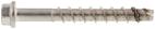
TECHNICAL DATA VERSION
CHARACTERISTICS
A4
RANGE Minimum anchorage depth Maximum anchorage depth Thread Ø Drilling Ø Total anchor length Tighten torque Code Embed. depth Max. thick. of part to be fixed Drilling depth Min. thick. of base material Embed. depth Max. thick. of part to be fixed Drilling depth Min. thick. of base material (mm) (mm) (mm) (mm) (mm) (mm) (mm) (mm) (mm) (mm) (mm) (Nm) h nom,1 t fix h 0 h min h nom,2 t fix h 0 h min d d 0 L T inst HFL 6X50/15 35 15 45 80 45 5 55 80 7,6 6 50 10 05 8651 6X60/25-5 25 15 60 058652 8X70/25-5 4 5 25 55 80 65 5 75 120 10,5 8 70 20 05 8655 8X80/35-15 35 15 80 058656 10X90/35-5 55 35 65 100 85 5 95 130 12,5 10 90 40 05 8657 10X100/45-15 45 15 100 05 8658 10X120/65-35 65 35 120 05 8659 CSK 8X80/35-15 45 35 55 80 65 15 75 120 10,5 8 80 20 05 8653 10X90/35-5 45 35 65 100 85 5 95 130 12,5 10 90 40 05 8654 df HFL CSK d0 tfix hmin h0 L d hnom Tinst ⁃ Channel, cable tray ⁃ Brackets ⁃ E-Clips, cowhorn ⁃ TRH clip, rod hanging ⁃ Trunking ⁃ Push-pull bars ⁃ Formwork / shuttering ⁃ Safety barriers ⁃ Stadium seats ETA - 22/0364 ETA ANCHOR MECHANICAL PROPERTIES SIZE Ø6 Ø8 Ø10 As [mm2] Stressed cross-section 20,4 36,3 60,8 Wel [mm3] Elastic section modulus 13,0 30,8 66,9 M0Rk,s [Nm] Characteristic bending moment 10,9 26,0 56,0 M [Nm] Recommended bending moment 5,0 13,0 28,0 SW [mm] Key size 13 13 15
APPLICATION
INSTALLATION
STAINLESS STEEL
XTREM
41
TAPCON
LT a4
TAPCON XTREM LT a4
MINIMUM THICKNESS OF CONCRETE, CHARATERISTIC & MINIMUM DISTANCES FOR SPACING, EDGE
CHARACTERISTIC RESISTANCES [kN]
Characteristic resistances are shown as informative, and have to be used by application of safety factors.
RECOMMENDED LOADS OF ONE ANCHOR WITHOUT INFLUENCE OF SPACING & CONCRETE EDGE [kN]
SHEAR
CRACKED
SIZE Ø6 Ø6 Ø8 Ø8 Ø10 Ø10 Embedment depth hnom [mm] 35 (1) 45 45 65 55 85 Minimum thickness of base material hmin [mm] 80 80 80 120 100 130 Characteristic edge and spacing distance for full anchor capacity Ccr ≥ [mm] 37,5 51,0 48,0 73,5 60,0 97,5 Scr ≥ [mm] 75 102 96 147 120 195 Minimum distances for cracked and non-cracked concrete Cmin [mm] 35 35 35 35 40 40 S ≥ [mm] Smin [mm] 35 35 35 35 40 40 C ≥ [mm] TENSILE NON-CRACKED CONCRETE ‒ C20/25 SIZE Ø6 Ø8 Ø10 hnom,1 [mm] 35 (1) 45 55 NRk,p [kN] 3,5 9,0 11,0 hnom,2 [mm] 45 65 85 NRk,p [kN] 4,0 17,0 25,0 CRACKED CONCRETE ‒ C20/25 SIZE Ø6 Ø8 Ø10 hnom,1 [mm] 35 (1) 45 55 NRk,p [kN] 2,5 3,0 6,0 hnom,2 [mm] 45 65 85 NRk,p [kN] 1,5 8,0 17,0
SHEAR CRACKED AND NON-CRACKED CONCRETE ‒ C20/25 to C50/60 SIZE Ø6 Ø8 Ø10 hnom,1 [mm] 35 (1) 45 55 VRk,s [kN] 7,0 13,5 22,5 hnom,2 [mm] 45 65 85 VRk,s [kN] 7,0 17,0 34,0 TENSILE NON-CRACKED CONCRETE ‒ C20/25 SIZE Ø6 Ø8 Ø10 hnom,1 [mm] 35 (1) 45 55 NRec [kN] 1,7 4,3 5,2 hnom,2 [mm] 45 65 85 NRec [kN] 1,9 8,1 11,9 CRACKED CONCRETE ‒ C20/25 SIZE Ø6 Ø8 Ø10 hnom,1 [mm] 35 (1) 45 55 NRec [kN] 1,2 1,4 2,9 hnom,2 [mm] 45 65 85 NRec [kN] 0,7 3,8 8,1 NRec = min [NRd,p ; NRd,c; NRd,s] / γF ; γF = 1,4 Recommended values are determined from performances given in the ETA, and are guaranteed for spacing ≥ Scr and edge distance ≥ Ccr
AND NON-CRACKED CONCRETE ‒ C20/25
C50/60 SIZE Ø6 Ø8 Ø10 hnom,1 [mm] 35 (1) 45 55 VRec [kN] 4,0 7,7 12,9 hnom,2 [mm] 45 65 85 VRec [kN] 4,0 9,7 19,4 VRec = VRd,s / γF ; γF = 1,4 (1) Only for statically indeterminate non-structural systems (multiple use) Nota: The values indicated in italics and underlined correspond to steel failure
to
42
XTREM LT a4
i-Expert
Software
DESIGN RESISTANCE FOR STATIC LOADS IN NON CRACKED CONCRETE [kN]
DESIGN RESISTANCE FOR STATIC LOADS IN CRACKED CONCRETE [kN]
DESIGN RESISTANCE FOR SEISMIC LOADS CATEGORY C1 [kN]
DESIGN RESISTANCE FOR FIRE EXPOSURE [kN]
TENSILE SIZE Ø6 Ø8 Ø10 hnom,1 [mm] 35 (1) 45 55 NRd,uncr [kN] C20/25 2,3 6,0 7,3 C40/50 3,3 8,4 10,4 hnom,2 [mm] 45 65 85 NRd,uncr [kN] C20/25 2,7 11,3 16,7 C40/50 3,8 15,9 23,6 Distances Scr and Ccr must be fulfilled NRd,uncr = min[NRk,p,uncr / γMc ; NRk,s / γMs,N] γMc = 1,5 ; γMs,N = 1,5 SHEAR SIZE Ø6 Ø8 Ø10 hnom,1 [mm] 35 (1) 45 55 VRd,s [kN] ≥ C20/25 5,6 10,8 18,0 hnom,2 [mm] 45 65 85 VRd,s [kN] ≥ C20/25 5,6 13,6 27,2 VRd,s = VRk,s /γMs,V γMs,V = 1,25 TENSILE SIZE Ø6 Ø8 Ø10 hnom,1 [mm] 35 (1) 45 55 NRd,cr [kN] C20/25 1,7 2,0 4,0 C40/50 2,4 2,8 5,7 hnom,2 [mm] 45 65 85 NRd,cr [kN] C20/25 1,0 5,3 11,3 C40/50 1,4 7,5 16,0 Distances Scr and Ccr must be fulfilled NRd,cr = min[NRk,p,cr / γMc ; NRk,s / γMs,N] γMc = 1,5 ; γMs,N = 1,5 SHEAR SIZE Ø6 Ø8 Ø10 hnom,1 [mm] 35 (1) 45 55 VRd,s [kN] ≥ C20/25 5,6 10,8 18,0 hnom,2 [mm] 45 65 85 VRd,s [kN] ≥ C20/25 5,6 13,6 27,2 VRd,s = VRk,s / γMs,V γMs,V = 1,25
TENSILE SIZE Ø6 Ø8 Ø10 hnom,2 [mm] 45 65 85 NRd,fi R30 [kN] 0,9 2,4 4,4 NRd,fi R60 [kN] 0,8 1,7 3,3 NRd,fi R90 [kN] 0,6 1,1 2,3 NRd,fi R120 [kN] 0,4 0,7 1,7 NRd,fi = NRk,s,fi /γM,fi γM,fi = 1,0 SHEAR SIZE Ø6 Ø8 Ø10 hnom,2 [mm] 45 65 85 VRd,fi R30 [kN] 0,9 2,4 4,4 VRd,fi R60 [kN] 0,8 1,7 3,3 VRd,fi R90 [kN] 0,6 1,1 2,3 VRd,fi R120 [kN] 0,4 0,7 1,7 VRd,fi = VRk,s,fi /γM,fi γM,fi = 1,0
SHEAR SIZE Ø6 Ø8 Ø10 hnom,1 [mm] - 45 55 hnom,2 [mm] 45 65 85 VRd,s,C1 [kN] ≥ C20/25 2,8 8,0 11,2 VRd,s,C1 = VRk,s,eq,C1 / γMs,V γMs,V = 1,25 TENSILE SIZE Ø6 Ø8 Ø10 hnom,1 [mm] - 45 55 NRd,C1 [kN] C20/25 - 2,0 4,0 C40/50 - 2,8 5,7 hnom,2 [mm] 45 65 85 NRd,C1 [kN] C20/25 1,0 5,7 11,3 C40/50 1,4 8,0 16,0 Distances Scr and Ccr must be fulfilled NRd,C1 = min[NRk,p,eq,C1 / γMc ; NRk,s,eq,C1 / γMs,N] γMc = 1,5 ; γMs,N = 1,5 Nota: The values indicated in italics and underlined correspond to steel failure
(1) Only for statically indeterminate non-structural systems (multiple use) TAPCON
Design resistances for static, seismic and fire loads are determined from performances given in the ETA, and are guaranteed for spacing ≥ Scr and edge distance ≥ Ccr. For project with reduced spacing and edge distance, we recommend to use SPIT i-Expert software to design your project according to EN 1992-4. 43
TAPCON
Concrete screw anchor, for use in cracked and non-cracked concrete, and hollow concrete slab
TECHNICAL DATA VERSION RANGE Embed ment depth Max. thick. of part to be fixed Drilling depth Min. thick. of base material Thread Ø Drilling Ø Total anchor length Tighten torque Code (mm) (mm) (mm) (mm) (mm) (mm) (mm) (Nm) h nom t fix h 0 h min d d 0 L T inst HFL 5X40/5 35 5 40 80 6,5 5 40 8 058726 5X50/15 15 50 058727 5X60/25 25 60 058728 6X40/5 35 5 40 80 7,5 6 40 10 058729 CSK 5X40/5 35 5 40 80 6,5 5 40 8 058770 5X60/25 25 60 058771 6X40/5 35 5 40 80 7,5 6 40 10 058772 PAN 5X40/5 35 5 40 80 5 40 058779 5X50/15 15 6,5 50 8 058780 5X60/25 25 60 058781 6X30/5* 25 3 28 80 7,0 6 28 10 058787 6X40/5 35 5 40 7,5 40 058782 DOME 6X40/5 35 5 40 80 7,5 6 40 10 058783 6X60/5 25 60 058784 ROD 6X35/M6-M8 35 - 40 80 7,5 6 35 10 058788 6X35/M8-M10 35 - 40 80 35 058785 6X55/M8-M10 55 - 60 100 55 058786 ETA - 16/0373 * ETA - 17/0174 ETA
HFL CSK DOME ROD PAN df d0 tfix hmin h0 L d hnom Tinst ANCHOR MECHANICAL PROPERTIES SIZE Ø5 Ø6 As [mm2] Stressed cross-section 33,0 44,2 Wel [mm3] Elastic section modulus 27,0 41,4 M0Rk,s [Nm] Characteristic bending moment 5,3 10,0 M [Nm] Recommended bending moment 7,2 5,0 SW [mm] Key size 10 13 INSTALLATION ⁃ Channel, cable tray ⁃ Brackets ⁃ E-Clips, cowhorn ⁃ Rod hanging APPLICATION CHARACTERISTICS ZINC COATED STEEL Zn
44
MINIMUM THICKNESS OF CONCRETE, CHARATERISTIC & MINIMUM DISTANCES FOR SPACING, EDGE
CHARACTERISTIC RESISTANCES [kN]
Characteristic resistances are shown as informative, and have to be used by application of safety factors.
RECOMMENDED LOADS OF ONE ANCHOR WITHOUT INFLUENCE OF SPACING & CONCRETE EDGE [kN]
Recommended values are determined from performances given in the ETA, and are guaranteed for spacing ≥ Scr and edge distance ≥ Ccr
SIZE Ø5 Ø6X30 Ø6 Ø6 Embedment depth hnom [mm] 35 25 35 55 Minimum thickness of base material hmin [mm] 80 80 80 100 Characteristic edge and spacing distances for full anchor capacity Ccr ≥ [mm] 52,5 150 52,5 82,5 Scr ≥ [mm] 105 200 105 165 Minimum distances for cracked and non-cracked concrete Cmin [mm] 35 150 35 40 S ≥ [mm] Smin [mm] 35 200 35 40 C ≥ [mm] Minimum distances for hollow concrete slab Cmin [mm] - - 100 100 S ≥ [mm] Smin [mm] - - 100 100 C ≥ [mm]
TENSILE CRACKED AND NON-CRACKED CONCRETE ‒ C20/25 SIZE Ø5 Ø6X30 Ø6 Ø6 hnom [mm] 35 25 35 55 NRk,p [kN] 1,5 0,9 3,0 7,5 HOLLOW CONCRETE SLAB DIMENSIONS Ø5 Ø6X30 Ø6 Ø6 Bottom flange [mm] - - ≥ 25 ≥ 35 thickness NRk,p [kN] - - 1,0 3,0
CRACKED AND NON-CRACKED CONCRETE ‒ C20/25 to C50/60 SIZE Ø5 Ø6X30 Ø6 Ø6 hnom [mm] 35 25 35 55 VRk,s [kN] 4,4 0,9 7,0 7,0 HOLLOW CONCRETE SLAB DIMENSIONS Ø5 Ø6X30 Ø6 Ø6 Bottom flange [mm] - - ≥ 25 ≥ 35 thickness VRk,p [kN] - - 1,0 3,0
SHEAR
TENSILE CRACKED AND NON-CRACKED CONCRETE ‒ C20/25 SIZE Ø5 Ø6X30 Ø6 Ø6 hnom [mm] 35 25 35 55 NRec [kN] 0,6 0,4 1,4 3,6 NRec = min [NRd,p ; NRd,c; NRd,s] / γF ; γF = 1,4 HOLLOW CONCRETE SLAB DIMENSIONS Ø5 Ø6X30 Ø6 Ø6 Bottom flange [mm] - - ≥ 25 ≥ 35 thickness NRec [kN] - - 0,5 1,4 NRec = min [NRd,p ; NRd,c; NRd,s] / γF ; γF = 1,4 SHEAR CRACKED AND NON-CRACKED CONCRETE ‒ C20/25 to C50/60 SIZE Ø5 Ø6X30 Ø6 Ø6 hnom [mm] 35 25 35 55 VRec [kN] 2,5 0,4 4,0 4,0 VRec = VRd,s / γF ; γF = 1,4 HOLLOW CONCRETE SLAB DIMENSIONS Ø5 Ø6X30 Ø6 Ø6 Bottom flange [mm] - - ≥ 25 ≥ 35 thickness VRec [kN] - - 0,5 1,4 VRec = VRd,s / γF ; γF = 1,4 Nota: The values indicated in italics and underlined correspond to steel failure TAPCON 45
TAPCON
i-Expert Software
Design resistances for static and fire loads are determined from performances given in the ETA, and are guaranteed for spacing ≥ Scr and edge distance ≥ Ccr. For project with reduced spacing and edge distance, we recommend to use SPIT i-Expert software to design your project according to EN 1992-4.
DESIGN RESISTANCE FOR STATIC LOADS IN CRACKED AND NON CRACKED CONCRETE [kN]
DESIGN RESISTANCE FOR STATIC LOADS IN HOLLOW CONCRETE SLAB [kN]
DESIGN RESISTANCE FOR FIRE EXPOSURE [kN]
TENSILE SIZE Ø5 Ø6X30 Ø6 Ø6 hnom [mm] 35 25 35 55 NRd,uncr [kN] C20/25 0,8 0,6 2,0 5,0 C40/50 1,2 0,6 2,8 7,1 Distances Scr and Ccr must be fulfilled NRd,uncr = min[NRk,p,uncr / γMc ; NRk,s / γMs,N] γMc = 1,5 ; γMs,N = 1,5 SHEAR SIZE Ø5 Ø6X30 Ø6 Ø6 hnom [mm] 35 25 35 55 VRd,s [kN] ≥ C20/25 3,5 0,6 5,6 5,6 VRd,s = VRk,s /γMs,V γMs,V = 1,25 ; Ø6X30: γMs,V = 1,5 TENSILE SIZE Ø5 Ø6X30 Ø6 Ø6 Bottom flange [mm] - - ≥ 25 ≥ 35 thickness NRd [kN] - - 0,7 2,0 Distances Scr and Ccr must be fulfilled NRd = min[NRk,p / γMc ; NRk,s / γMs,N] γMc = 1,5 ; γMs,N = 1,5 SHEAR SIZE Ø5 Ø6X30 Ø6 Ø6 Bottom flange [mm] - - ≥ 25 ≥ 35 thickness VRd,s [kN] - - 0,7 2,0 VRd,s = VRk,s / γMs,V γMs,V = 1,25
TENSILE SIZE Ø5 Ø6X30 Ø6 Ø6 hnom [mm] 35 25 35 55 NRd,fi R30 [kN] - 0,27 0,75 0,90 NRd,fi R60 [kN] - 0,27 0,75 0,80 NRd,fi R90 [kN] - 0,22 0,60 0,60 NRd,fi R120 [kN] - 0,17 0,40 0,40 NRd,fi = NRk,s,fi /γM,fi γM,fi = 1,0 SHEAR SIZE Ø5 Ø6X30 Ø6 Ø6 hnom [mm] 35 25 35 55 VRd,fi R30 [kN] - 0,27 0,75 0,90 VRd,fi R60 [kN] - 0,27 0,75 0,80 VRd,fi R90 [kN] - 0,22 0,60 0,60 VRd,fi R120 [kN] - 0,17 0,40 0,40 VRd,fi = VRk,s,fi /γM,fi ; γM,fi = 1,0 γM,fi = 1,0
Nota: The values indicated in italics and underlined correspond to steel failure
46
Deformation-controlled expansion female anchor for use in cracked and non-cracked concrete and hollow concrete slab
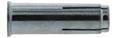
d0 L = hef Tinst h1 LS d hmin ⁃ Ventilation ducts ⁃ Suspended ceilings ⁃ Cable trays ⁃ Sprinkler system ETA - 21/0176 ETA ANCHOR MECHANICAL PROPERTIES DIMENSIONS M6 M8 M10 M12 M16 Zinc coated steel M0Rk,s [Nm] Characteristic bending moment (grade 4.6/4.8) 6,1 15,0 29,9 52,4 133,3 (grade 5.6/5.8) 7,6 18,8 37,4 65,5 166,6 (grade 6.8) 9,2 22,5 44,9 78,7 199,9 (grade 8.8) 12,2 30.0 59,9 104,9 266,6 Stainless steel A4 M0Rk,s [Nm] Characteristic bending moment (grade A4-50) 7,6 18,8 37,4 65,5 166,6 (grade A4-70) 10,6 26,3 52,4 91,8 233,1 (grade A4-80) 12,2 30.0 59,9 104,9 266,6
INSTALLATION APPLICATION TECHNICAL DATA RANGE Min. anchor depth Thread diameter Thread length Drilling depth Drilling diameter Min. thick of base material Total anchor length Tighten torque Code Zinc coated steel Code stainless steel A4 Setting tool (mm) (mm) (mm) (mm) (mm) (mm) (mm) (Nm) h ef d L s h1 d 0 h min L T inst M6X25 25 6 10 27 8 100 25 4 058581 058589 ST-M M6x25 058596 M8X30 30 8 13 33 10 100 30 11 058583 058591 ST-M M8x30 058597 M10X25* 25 10 13 28 12 80 25 17 058584 - ST-M M10x25 058598 M10X40 40 10 17 43 12 100 40 17 058585 058592 ST-M M10x40 058599 M12X50 50 12 21 54 15 100 50 38 058586 058593 ST-M M12x50 058601 M16X65 65 16 27 70 20 130 65 60 058587 058594 ST-M M16x65 058602 * Zinc coated steel only CHARACTERISTICS ZINC COATED STEEL Zn STAINLESS STEEL A4 Vds CEA 4001 M8 - M16 GRIP+L/GRIP+A4 47
GRIP+L/GRIP+a4
MINIMUM THICKNESS OF CONCRETE, CHARATERISTIC & MINIMUM DISTANCES FOR SPACING, EDGE
CHARACTERISTIC RESISTANCES [kN]
Characteristic resistances are shown as informative, and have to be used by application of safety factors.
CRACKED
NON-CRACKED CONCRETE ‒ C20/25 to C50/60
‒ C20/25 to C50/60
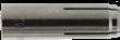
HOLLOW CONCRETE SLAB Zinc
RECOMMENDED LOADS OF ONE ANCHOR WITHOUT INFLUENCE OF SPACING & CONCRETE EDGE [kN]
Recommended values are determined from performances given in the ETA, and are guaranteed for spacing ≥ Scr and edge distance ≥ Ccr TENSILE
SHEAR
CRACKED AND NON-CRACKED CONCRETE ‒ C20/25 to C50/60
HOLLOW CONCRETE SLAB Zinc
Zinc coated steel SIZE M6 M8 M10 M10 M12 M16 Anchorage depth hef [mm] 25 30 25 40 50 65 Minimum thickness of base material hmin [mm] 100 100 80 100 100 130 Characteristic edge and spacing distance for full anchor capacity Ccr ≥ [mm] 37,5 45 60 60 75 97,5 Scr ≥ [mm] 75 90 120 120 150 195 Minimum distances for cracked and non-cracked concrete Cmin [mm] 60 60 75 80 100 130 Smin [mm] 105 105 60 140 175 230 Stainless steel A4 SIZE M6 M8 M10 M10 M12 M16 Anchorage depth hef [mm] 25 30 - 40 50 65 Minimum thickness of base material hmin [mm] 80 80 - 80 100 130 Characteristic edge and spacing distance for full anchor capacity Ccr ≥ [mm] 150 150 - 60 150 195 Scr ≥ [mm] 200 200 - 120 200 260 Minimum distances for cracked and non-cracked concrete Cmin [mm] 60 60 - 100 100 130 Smin [mm] 65 80 - 100 130 175 TENSILE
Zinc coated steel SIZE M6 M8 M10 M10 M12 M16 hef [mm] 25 30 25 40 50 65 NRk,cr [kN] 1,5 3,0 4,0 5,0 7,5 12,0 Stainless steel A4 SIZE M6 M8 M10 M10 M12 M16 hef [mm] 25 30 25 40 50 65 NRk,cr [kN] 2,5 3,5 - 3,5 6,5 12,5 HOLLOW CONCRETE SLAB Zinc coated steel SIZE M6 M8 M10 M10 M12 M16 Bottom flange [mm] ≥ 25 ≥ 25 ≥ 35 - -thickness NRk,p [kN] 6,0 6,0 8,0 -
-
AND
-
SHEAR CRACKED AND
CONCRETE
Zinc coated steel SIZE M6 M8 M10 M10 M12 M16 hef [mm] 25 30 25 40 50 65 VRk,cr [kN] 1,5 3,0 4,0 5,0 7,5 12,0 Stainless steel A4 SIZE M6 M8 M10 M10 M12 M16 hef [mm] 25 30 25 40 50 65 VRk,cr [kN] 2,5 3,5 - 3,5 6,5 12,5
NON-CRACKED
coated steel SIZE M6 M8 M10 M10 M12 M16 Bottom flange [mm] ≥ 25 ≥ 25 ≥ 35 - -thickness VRk [kN] 3,6 6,7 10,5 -
- -
CRACKED AND NON-CRACKED CONCRETE ‒ C20/25 to C50/60 Zinc coated steel SIZE M6 M8 M10 M10 M12 M16 hef [mm] 25 30 25 40 50 65 NRec [kN] 0,6 1,2 1,6 1,7 2,6 4,1 Stainless steel A4 SIZE M6 M8 M10 M10 M12 M16 hef [mm] 25 30 25 40 50 65 NRec [kN] 0,9 1,2 - 1,2 2,2 4,3
CONCRETE SLAB Zinc coated steel SIZE M6 M8 M10 M10 M12 M16 Bottom flange [mm] ≥ 25 ≥ 25 ≥ 35 - -thickness NRk,p [kN] 2,0 2,0 2,7 - -NRec = NRd,cr / γF ; γF = 1,4
HOLLOW
Zinc coated steel SIZE M6 M8 M10 M10 M12 M16 hef [mm] 25 30 25 40 50 65 VRec [kN] 0,6 1,2 1,6 1,7 2,6 4,1 Stainless steel A4 SIZE M6 M8 M10 M10 M12 M16 hef [mm] 25 30 25 40 50 65 VRec [kN] 0,9 1,2 - 1,2 2,2 4,3
SIZE M6 M8 M10 M10 M12 M16 Bottom flange [mm] ≥ 25 ≥ 25 ≥ 35 - -thickness VRec [kN] 2,0 2,0 2,7 - -VRec = VRd / γF ; γF = 1,4
coated steel
48
Design resistances for static and fire loads are determined from performances given in the ETA, and are guaranteed for spacing ≥ Scr and edge distance ≥ Ccr. For project with reduced spacing and edge distance, we recommend to use SPIT i-Expert software to design your project according to EN 1992-4.
DESIGN RESISTANCE FOR STATIC LOADS IN CRACKED & NON-CRACKED CONCRETE [kN]
DESIGN RESISTANCE FOR STATIC LOADS IN HOLLOW CONCRETE SLAB [kN]
DESIGN RESISTANCE FOR FIRE EXPOSURE [kN]
TENSILE CRACKED AND NON-CRACKED CONCRETE ‒ C20/25 to C50/60 Zinc coated steel SIZE M6 M8 M10 M10 M12 M16 hef [mm] 25 30 25 40 50 65 NRd,cr [kN] 0,83 1,7 2,2 2,4 3,6 5,7 Stainless steel A4 SIZE M6 M8 M10 M10 M12 M16 hef [mm] 25 30 25 40 50 65 NRd,cr [kN] 1,2 1,7 - 1,7 3,1 6,0 Distances Scr and Ccr must be fulfilled NRd,cr = NRk,p,cr / γMc Zinc coated steel: M6-M8-M10x25 : γMc = 1,8 ; M10x40-M12-M16 : γMc = 2,1 Stainless steel A4 : γMc = 2,1 SHEAR CRACKED AND NON-CRACKED CONCRETE ‒ C20/25 to C50/60 Zinc coated steel SIZE M6 M8 M10 M10 M12 M16 hef [mm] 25 30 25 40 50 65 VRd,cr [kN] 0,83 1,7 2,2 2,4 3,6 5,7 Stainless steel A4 SIZE M6 M8 M10 M10 M12 M16 hef [mm] 25 30 25 40 50 65 VRd,cr [kN] 1,2 1,7 - 1,7 3,1 6,0 VRd,cr = VRk,cr / γMc Zinc coated steel: M6-M8-M10x25 : γMc = 1,8 ; M10x40-M12-M16 : γMc = 2,1 Stainless steel A4 : γMc = 2,1
TENSILE Zinc coated steel SIZE M6 M8 M10 M10 M12 M16 hef [mm] 25 30 25 40 50 65 NRd,fi R30 [kN] 0,2 0,4 0,54 0,9 1,7 3,1 NRd,fi R60 [kN] 0,2 0,3 0,54 0,6 1,3 2,4 NRd,fi R90 [kN] 0,1 0,3 0,54 0,6 1,1 2,0 NRd,fi R120 [kN] 0,1 0,2 0,43 0,5 0,8 1,6 Stainless steel A4 SIZE M6 M8 M10 M10 M12 M16 hef [mm] 25 30 25 40 50 65 NRd,fi R30 [kN] 0,20 0,73 - 0,87 1,63 2,19 NRd,fi R60 [kN] 0,18 0,59 - 0,87 1,63 3,19 NRd,fi R90 [kN] 0,14 0,44 - 0,87 1,63 3,14 NRd,fi R120 [kN] 0,10 0,37 - 0,69 1,30 2,51 NRd,fi = NRk,s,fi /γM,fi γM,fi = 1,0 SHEAR Zinc coated steel SIZE M6 M8 M10 M10 M12 M16 hef [mm] 25 30 25 40 50 65 VRd,fi R30 [kN] 0,2 0,4 0,54 0,9 1,7 3,1 VRd,fi R60 [kN] 0,2 0,3 0,54 0,6 1,3 2,4 VRd,fi R90 [kN] 0,1 0,3 0,54 0,6 1,1 2,0 VRd,fi R120 [kN] 0,1 0,2 0,43 0,5 0,8 1,6 Stainless steel A4 SIZE M6 M8 M10 M10 M12 M16 hef [mm] 25 30 25 40 50 65 VRd,fi R30 [kN] 0,20 0,73 - 0,87 1,63 2,19 VRd,fi R60 [kN] 0,18 0,59 - 0,87 1,63 3,19 VRd,fi R90 [kN] 0,14 0,44 - 0,87 1,63 3,14 VRd,fi R120 [kN] 0,10 0,37 - 0,69 1,30 2,51 VRd,fi = VRk,s,fi /γM,fi γM,fi = 1,0
TENSILE Zinc coated steel SIZE M6 M8 M10 M10 M12 M16 Bottom flange [mm] ≥ 25 ≥ 25 ≥ 35 - -thickness NRd [kN] 2,9 2,9 3,8 - -NRd = NRk,p / γMc γMc = 2,1 SHEAR Zinc coated steel SIZE M6 M8 M10 M10 M12 M16 Bottom flange [mm] ≥ 25 ≥ 25 ≥ 35 - -thickness VRd [kN] 1,75 3,2 5,0 - -VRd = VRk / γMc γMc = 2,1 i-Expert Software GRIP+L/GRIP+A4 49
PRIMA
High expansion shield anchor, for use in concrete and solid & hollow masonries and hollow concrete slab
MINIMUM THICKNESS OF CONCRETE, CHARATERISTIC & MINIMUM DISTANCES FOR SPACING, EDGE
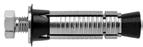
MASONRIES d0 hef Tinst hmin h0 L d tfix df Technical Assessment SOCOTEC N° KX 0827
INSTALLATION ⁃ Industrial doors ⁃ Storage racking ⁃ Signs ⁃ Security shutters ⁃ Gate & fence posts ⁃ Spiral staircase APPLICATION CHARACTERISTICS TECHNICAL DATA RANGE Min. anchor depth Max.thick of part to be fixed Thread diameter Drilling depth Drilling diameter Min. thick of base material Clearance diameter Total anchor length Tighten torque Code Concrete Bricks screw 5.8 screw 8.8 (mm) (mm) (mm) (mm) (mm) (mm) (mm) (mm) (Nm) (Nm) (Nm) h ef t fix d h 0 d 0 h min df L T inst T inst T inst SHIELD ONLY M6X50 37 - M6 60 12 100 8 50 8 10 5 050399 M8X55 42 - M8 65 14 100 10 55 15 25 7,5 050401 M10X65 52 - M10 75 16 100 12 65 30 50 13 050402 M12X80 62 - M12 90 20 125 14 80 50 80 23 073560 TYPE B (SUPPLIED WITH SCREW GRADE 8.8 AND PREMOUNTED WASHER) M6X50/10 B 37 10 M6 60 12 100 8 60 - 10 5 050404 M6X50/25 B 25 70 050405 M8X55/10 B 42 10 M8 65 14 100 10 60 - 25 7,5 050406 M8X55/25 B 25 80 050407 M8X55/40 B 40 90 050408 M10X65/10 B 52 10 M10 75 16 100 12 75 - 50 13 073640 M10X65/25 B 25 90 073650 M10X65/50 B 50 110 073660 M12X80/10 B 62 10 M12 90 20 125 14 90 - 80 23 073680 M12X80/25 B 25 110 073690
MECHANICAL PROPERTIES SIZE M6 M8 M10 M12 Screw grade 5.8 fuk [N/mm2] Min. tensile strength 520 520 520 520 fyk [N/mm2] Yield strength 420 420 420 420 M0Rk,s [Nm] Characteristic bending moment 7,9 19,5 38,9 68,1 M [Nm] Recommended bending moment 3,2 7,8 15,6 28,4 As [mm2] Stressed cross-section 20,1 36,6 58 84,3 Wel [mm2] Elastic section modulus 12,7 31,2 62,3 109,2 Screw grade 8.8 fuk [N/mm2] Min. tensile strength 800 800 800 800 fyk [N/mm2] Yield strength 640 640 640 640 M0Rk,s [Nm] Characteristic bending moment 12,2 30,0 59,8 104,8 M [Nm] Recommended bending moment 5,0 12,4 24,8 43,7 As [mm2] Stressed cross-section 20,1 36,6 58 84,3 Wel [mm2] Elastic section modulus 12,7 31,2 62,3 109,2 SW [mm] Key size 10 13 17 19
ANCHOR
SIZE M6 M8 M10 M12 Embedment depth hnom [mm] 37 42 52 62 Minimum thickness of base material hmin [mm] 100 100 100 100 Characteristic edge and spacing distance for full anchor capacity NON CRACKED CONCRETE Ccr ≥ [mm] 55 63 78 93 Scr ≥ [mm] 110 126 156 186 MASONRIES Ccr ≥ [mm] 200 200 200 200 Scr ≥ [mm] 200 200 200 200 Minimum distances NON CRACKED CONCRETE Cmin [mm] 50 55 60 65 Smin [mm] 60 70 80 110 ZINC COATED STEEL Zn
50
CHARACTERISTIC RESISTANCES [kN]
Characteristic resistances are shown as informative, and have to be used by application of safety factors.
RECOMMENDED LOADS OF ONE ANCHOR WITHOUT INFLUENCE OF SPACING & CONCRETE EDGE [kN]
SLAB (type DSL 20)
HOLLOW CONCRETE SLAB (type DSL 20)
TENSILE NON-CRACKED CONCRETE ‒ C20/25 SIZE M6 M8 M10 M12 hef [mm] 37 42 52 62 NRk,p [kN] 10,5 13,4 18,4 24,0 MASONRIES SIZE M6 M8 M10 M12 hef [mm] 37 42 52 62 Engineering clay bricks BP 300 (fb > 30 N/mm²) NRk [kN] 7,6 9,6 12,0 12,0 Clay bricks (fb = 11 N/mm²) NRk [kN] 2,8 4,4 4,4 8,0 Solid concrete blocks B 120 (fb = 13,5 N/mm²) NRk [kN] 1,6 3,8 5,0 7,6 Hollow clay bricks not rendered NRk [kN] 0,6 0,6 -Hollow clay bricks rendered NRk [kN] 4,8 4,8 4,8 4,8 Hollow concrete blocks not rendered NRk [kN] 0,8 0,8 -Hollow concrete blocks rendered NRk [kN] 5,0 7,0 7,4 8,8
SHEAR NON-CRACKED CONCRETE ‒ C20/25 to C50/60 SIZE M6 M8 M10 M12 hef [mm] 37 42 52 62 Screw grade 8.8 8,1 14,6 23,3 33,0 VRk,s [kN] Screw grade 5.8 5,2 9,5 15,1 21,9 VRk,s [kN] MASONRIES SIZE M6 M8 M10 M12 hef [mm] 37 42 52 62 Engineering clay bricks BP 300 (fb > 30 N/mm²) VRk [kN] 4,0 7,6 12,0 17,6 Clay bricks (fb = 11 N/mm²) VRk [kN] 3,4 7,6 12,0 17,6 Solid concrete blocks B 120 (fb = 13,5 N/mm²) VRk [kN] 2,0 7,0 8,8 12,6 Hollow clay bricks not rendered VRk [kN] 2,0 2,0 -Hollow clay bricks rendered VRk [kN] 6,4 8,0 10,0 12,0 Hollow concrete blocks not rendered VRk [kN] 3,2 3,2 -Hollow concrete blocks rendered VRk [kN] 6,4 8,0 10,0 12,0
Recommended values are given for spacing ≥ Scr and edge distance ≥ Ccr TENSILE NON-CRACKED CONCRETE ‒ C20/25 SIZE M6 M8 M10 M12 hef [mm] 37 42 52 62 NRec [kN] 3,6 4,6 6,3 8,2 NRec = NRd,uncr / γF ; γF = 1,5 MASONRIES SIZE M6 M8 M10 M12 hef [mm] 37 42 52 62 Engineering clay bricks BP 300 (fb > 30 N/mm²) NRec [kN] 1,90 2,40 3,00 3,00 Clay bricks (fb = 11 N/mm²) NRec [kN] 0,70 1,10 1,10 2,00 Solid concrete blocks B 120 (fb = 13,5 N/mm²) NRec [kN] 0,40 0,95 1,25 1,90 Hollow clay bricks not rendered NRec [kN] 0,15 0,15 -
Hollow clay bricks rendered NRec [kN] 1,20 1,20 1,20 1,20 Hollow concrete blocks not rendered NRec [kN] 0,20 0,20
Hollow concrete blocks rendered NRec [kN] 1,25 1,75 1,85 2,20 NRec = NRd / γF ; γF = 1,5
CONCRETE
SIZE M6 M8 M10 M12 hef [mm] 37 42 52 62 NRec [kN] 2,50 2,75 3,00NRec = NRd / γF ; γF = 1,5 SHEAR NON-CRACKED CONCRETE ‒ C20/25 to C50/60 SIZE M6 M8 M10 M12 hef [mm] 37 42 52 62 Screw grade 8.8 4,6 8,4 13,3 18,9 VRec [kN] Screw grade 5.8 2,5 4,5 7,2 10,4 VRec [kN] VRec = VRd,s / γF ; γF = 1,25 MASONRIES SIZE M6 M8 M10 M12 hef [mm] 37 42 52 62 Engineering clay bricks BP 300 (fb > 30 N/mm²) VRec [kN] 1,00 1,90 3,00 4,40 Clay bricks (fb = 11 N/mm²) VRec [kN] 0,85 1,90 3,00 4,40 Solid concrete blocks B 120 (fb = 13,5 N/mm²) VRec [kN] 0,50 1,75 2,20 3,15 Hollow clay bricks not rendered VRec [kN] 0,50 0,50 -Hollow clay bricks rendered VRec [kN] 1,60 2,00 2,50 3,00 Hollow concrete blocks not rendered VRec [kN] 0,80 0,80 -Hollow concrete blocks rendered VRec [kN] 1,60 2,00 2,50 3,00 VRec = VRd / γF ; γF = 1,25
-
- -
HOLLOW
SIZE M6 M8 M10 M12 hef [mm] 37 42 52 62 Screw grade 8.8 2,10 3,90 6,20 - VRec [kN] Screw grade 5.8 1,40 2,50 4,00 - VRec [kN] VRec = VRd,s / γF ; γF = 1,25
Nota: The values indicated in italics and underlined correspond to steel failure PRIMA 51
PRIMA
Design resistances for static and fire loads are given for spacing ≥ Scr and edge distance ≥ Ccr For project with reduced spacing and edge distance, we recommend to use SPIT i-Expert software to design your project according to EN 1992-4.
DESIGN RESISTANCE FOR STATIC LOADS IN NON-CRACKED CONCRETE [kN]
DESIGN RESISTANCE FOR STATIC LOADS IN MASONRIES [kN]
DESIGN RESISTANCE FOR STATIC LOADS IN HOLLOW CONCRETE SLAB [kN]
DESIGN RESISTANCE FOR FIRE EXPOSURE [kN]
TENSILE SIZE M6 M8 M12 M16 hef [mm] 37 42 52 62 NRd,fi R30 [kN] - 1,09 1,20 1,20 NRd,fi R60 [kN] - 0,89 1,10 1,10 NRd,fi R90 [kN] - 0,68 1,04 1,04 NRd,fi R120 [kN] - 0,58 1,00 1,00 NRd,fi = NRk,s,fi /γM,fi γM,fi = 1,0 SHEAR SIZE M6 M8 M12 M16 hef [mm] 37 42 52 62 VRd,fi R30 [kN] - 1,09 1,20 1,20 VRd,fi R60 [kN] - 0,89 1,10 1,10 VRd,fi R90 [kN] - 0,68 1,04 1,04 VRd,fi R120 [kN] - 0,58 1,00 1,00 VRd,fi = VRk,s,fi /γM,fi γM,fi = 1,0
TENSILE SIZE M6 M8 M12 M16 hef [mm] 37 42 52 62 NRd,uncr [kN] C20/25 5,0 6,4 8,8 11,4 C40/50 5,1 9,0 12,4 16,2 Distances Scr and Ccr must be fulfilled NRd,uncr = min[NRk,p,uncr / γMc ; NRk,s / γMs,N] γMc = 2,1 ; γMs,N = 1,5 SHEAR SIZE M6 M8 M12 M16 hef [mm] 37 42 52 62 Screw grade 8.8 6,5 11,7 18,6 26,4 VRd,s [kN] Screw grade 5.8 4,2 7,6 12,1 17,5 VRd,s [kN] VRd,s = VRk,s /γMs,V γMs,V = 1,25 Nota: The values indicated in italics and underlined correspond to steel failure TENSILE SIZE M6 M8 M10 M12 hef [mm] 37 42 52 62 Engineering clay bricks BP 300 (fb > 30 N/mm²) NRd [kN] 2,60 3,30 4,20 4,20 Clay bricks (fb = 11 N/mm²) NRd [kN] 1,00 1,50 1,50 2,80 Solid concrete blocks B 120 (fb = 13,5 N/mm²) NRd [kN] 0,55 1,30 1,30 2,60 Hollow clay bricks not rendered NRd [kN] 0,20 0,20 -Hollow clay bricks rendered NRd [kN] 1,70 1,70 1,70 1,70 Hollow concrete blocks not rendered NRd [kN] 0,28 0,28 -Hollow concrete blocks rendered NRd [kN] 1,75 2,45 2,60 3,10 Distances Scr and Ccr must be fulfilled NRd = NRk / γM γM = 2,5 SHEAR SIZE M6 M8 M10 M12 hef [mm] 37 42 52 62 Engineering clay bricks BP 300 (fb > 30 N/mm²) VRd [kN] 1,40 2,60 4,20 6,20 Clay bricks (fb = 11 N/mm²) VRd [kN] 1,20 2,60 4,20 6,20 Solid concrete blocks B 120 (fb = 13,5 N/mm²) VRd [kN] 0,70 2,45 3,10 4,20 Hollow clay bricks not rendered VRd [kN] 0,70 0,70 -Hollow clay bricks rendered VRd [kN] 2,20 2,80 3,50 4,20 Hollow concrete blocks not rendered VRd [kN] 1,10 1,10 -Hollow concrete blocks rendered VRd [kN] 2,20 2,80 3,50 4,20 VRd = VRk / γM ; γM = 2,5
TENSILE SIZE M6 M8 M10 M12 hef [mm] 37 42 52 62 NRd [kN] 2,50 2,75 3,00Distances Scr and Ccr must be fulfilled NRec = NRd / γF ; γF = 1,5 SHEAR SIZE M6 M8 M10 M12 hef [mm] 37 42 52 62 Screw grade 8.8 2,10 3,90 6,20 - VRd [kN] Screw grade 5.8 1,40 2,50 4,00 - VRd [kN] VRd = VRk / γM ; γM = 2,5
i-Expert Software
52
ETA-22/0628 ETA-22/0883
High expansion shield anchor, for use in cracked and non-cracked concrete and solid & hollow masonries
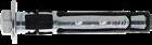
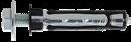
CHARACTERISTICS
MINIMUM THICKNESS OF CONCRETE, CHARATERISTIC & MINIMUM DISTANCES FOR SPACING, EDGE
TECHNICAL
RANGE Embed. depth Max. anchor depth Max. thick. of part to be fixed Thread Ø Drilling depth Drilling Ø Min. thick. of base material Clearance Ø Total screw length Tighten torque Code Concrete Masonry (mm) (mm) (mm) (mm) (mm) (mm) (mm) (mm) (mm) (Nm) (Nm) h nom h ef t fix d h 0 d 0 h min df L T inst T inst Type B (female version) M6x55/B 55 43 10 6 65 10 90 7 66 20 4-6 566476 M8x58/B 58 46 10 8 70 12 100 9 69 35 4-6 566477 M10x73/B 73 57 15 10 85 15 120 11 89 50 8-10 566478 Type P * (pass through version) M6x65/B-P 55 43 10 6 65 10 90 12 65 20 4-6 566479 M6x80/B-P 25 80 566480 M8x70/B-P 58 46 10 8 70 12 100 14 70 35 4-6 566481 M8x85/B-P 25 85 566482 d0 Tinst hmin h0 hef d tfix h nom L df TRINEO/B TRINEO/B-P ANCHOR MECHANICAL PROPERTIES SIZE M6 M8 M10 Screw grade 8.8 fuk [N/mm2] Min. tensile strength 800 800 800 fyk [N/mm2] Yield strength 640 640 640 M0Rk,s [Nm] Characteristic bending moment 12,2 30,0 59,8 M [Nm] Recommended bending moment 5,0 12,4 24,8 As [mm2] Stressed cross-section 20,1 36,6 58,0 Wel [mm3] Elastic section modulus 12,7 31,2 62,3 SW [mm] Key size 10 13 17
DATA
SIZE M6 M8 M10 Embedment depth hnom [mm] 55 58 73 Minimum thickness of base material hmin [mm] 90 100 120 Characteristic edge and spacing distance for full anchor capacity CRACKED & NON CRACKED CONCRETE Ccr ≥ [mm] 64,5 69 85,5 Scr ≥ [mm] 129 138 171 MASONRIES Ccr ≥ [mm] 200 200 200 Scr ≥ [mm] 200 200 200 Minimum distances CRACKED & NON CRACKED CONCRETE Cmin [mm] 55 60 120 for S ≥ [mm] 90 95 115 Smin [mm] 90 95 115 for C ≥ [mm] 55 60 120 SOLID MASONRIES Cmin [mm] 120 120 180 Smin // [mm] 480 480 720 Smin Ʇ [mm] 240 240 360 HOLLOW MASONRIES Cmin [mm] 100 100 100 Smin // [mm] 400 400 400 Smin Ʇ [mm] 200 200 200
INSTALLATION ⁃ Water heater ⁃ Lighting ⁃ Cable trays ⁃ Electrical swithboard ⁃ Pipes, collars ⁃ Cladding brackets APPLICATION
ZINC COATED STEEL Zn MASONRIES
ETA TRINEO/B 53
TRINEO/B
CHARACTERISTIC RESISTANCES [kN]
Characteristic resistances are shown as informative, and have to be used by application of safety factors.
RECOMMENDED LOADS OF ONE ANCHOR WITHOUT INFLUENCE OF SPACING & CONCRETE EDGE [kN]
Recommended values are determined from performances given in the ETA, and are guaranteed for spacing ≥ Scr and edge distance ≥ Ccr
Hollow clay brick Optibric PV 3+ (fb ≥ 8,75 N/mm²)
-Hollow clay brick Porotherm GF R20 Th+ (fb ≥ 10 N/mm²)
TENSILE CRACKED & NON CRACKED CONCRETE ‒ C20/25 SIZE M6 M8 M10 hnom [mm] 55 58 73 NRk,p [kN] 5,0 5,5 10,0 MASONRIES SIZE M6 M8 M10 hnom [mm] 55 58 73 Hollow concrete block B40 (fb ≥ 7,5 N/mm²) NRk [kN] 0,90 1,20 1,20 Hollow concrete block B40 (fb ≥ 5,4 N/mm²) NRk [kN] 0,75 0,90 0,90 Hollow concrete block BC20 (fb ≥ 8 N/mm²) NRk [kN] 1,50 1,50 2,00 Solid clay brick (fb ≥ 18 N/mm²) NRk [kN] 2,00 2,00 2,50 Hollow clay brick Poroton (fb ≥ 6 N/mm²) NRk [kN] 0,75 1,50 1,50 Hollow clay brick Optibric PV 3+ (fb ≥ 8,75 N/mm²) NRk [kN] 0,75 -Hollow clay brick Porotherm GF R20 Th+ (fb ≥ 10 N/mm²) NRk [kN] 0,75 -Hollow clay brick Porotherm R30 (fb ≥ 8 N/mm²) NRk [kN] 0,75 1,50 1,50
SHEAR CRACKED & NON CRACKED CONCRETE ‒ C20/25 to C50/60 SIZE M6 M8 M10 hnom [mm] 55 58 73 VRk,s [kN] 8,0 13,7 23,2 MASONRIES SIZE M6 M8 M10 hnom [mm] 55 58 73 Hollow
VRk [kN] 0,90 1,20 1,20 Hollow concrete block B40 (fb ≥ 5,4 N/mm²) VRk [kN] 0,75 0,90 0,90 Hollow concrete block BC20 (fb ≥ 8 N/mm²) VRk [kN] 1,50 1,50 2,00 Solid clay brick (fb ≥ 18 N/mm²) VRk [kN] 2,00 2,00 2,50 Hollow clay brick Poroton (fb ≥ 6 N/mm²) VRk [kN] 0,75 1,50 1,50 Hollow clay brick Optibric PV 3+ (fb ≥ 8,75 N/mm²) VRk [kN] 0,75 -Hollow clay brick Porotherm GF R20 Th+ (fb ≥ 10 N/mm²) VRk [kN] 0,75 -Hollow clay brick Porotherm R30 (fb ≥ 8 N/mm²) VRk [kN] 0,75 1,50 1,50
concrete block B40 (fb ≥ 7,5 N/mm²)
TENSILE CRACKED & NON CRACKED CONCRETE ‒ C20/25 SIZE M6 M8 M10 hnom [mm] 55 58 73 NRec [kN] 2,4 2,6 4,8 NRec = NRd,uncr / γF ; γF = 1,4 MASONRIES SIZE M6 M8 M10 hnom [mm] 55 58 73 Hollow concrete block B40 (fb ≥ 7,5 N/mm²) NRec [kN] 0,25 0,34 0,34 Hollow concrete block B40 (fb ≥ 5,4 N/mm²) NRec [kN] 0,21 0,26 0,26 Hollow concrete block BC20 (fb ≥ 8 N/mm²) NRec [kN] 0,43 0,57 0,57 Solid clay brick (fb ≥ 18 N/mm²) NRec [kN] 0,57 0,57 0,70 Hollow clay brick Poroton (fb ≥ 6 N/mm²) NRec [kN] 0,21 0,43 0,43 Hollow clay brick Optibric PV 3+ (fb ≥ 8,75 N/mm²) NRec [kN] 0,21 -Hollow clay brick Porotherm GF R20 Th+ (fb ≥ 10 N/mm²) NRec [kN] 0,21 -Hollow clay brick Porotherm R30 (fb ≥ 8 N/mm²) NRec [kN] 0,21 0,43 0,43 NRec = NRd / γF ; γF = 1,4
CRACKED
CONCRETE ‒ C20/25 to C50/60 SIZE M6 M8 M10 hnom [mm] 55 58 73 VRec [kN] 4,6 7,8 13,3 VRec = VRd,s / γF ; γF = 1,4 MASONRIES SIZE M6 M8 M10 hnom [mm] 55 58 73 Hollow concrete
N/mm²) VRec [kN] 0,25 0,34 0,34 Hollow
N/mm²) VRec [kN] 0,21 0,26 0,26 Hollow concrete
N/mm²) VRec [kN] 0,43 0,57 0,57 Solid clay brick (fb ≥
N/mm²) VRec [kN] 0,57 0,57 0,70 Hollow clay
(fb
N/mm²) VRec [kN] 0,21 0,43 0,43
VRec [kN]
VRec [kN]
Hollow
N/mm²) VRec [kN] 0,21 0,43 0,43 VRec = VRd / γF ; γF =
Nota: The values indicated in italics and underlined correspond to steel failure
SHEAR
& NON CRACKED
block B40 (fb ≥ 7,5
concrete block B40 (fb ≥ 5,4
block BC20 (fb ≥ 8
18
brick Poroton
≥ 6
0,21
0,21 - -
clay brick Porotherm R30 (fb ≥ 8
1,4
54
Design resistances for static loads are determined from performances given in the ETA, and are guaranteed for spacing ≥ Scr and edge distance ≥ Ccr. For project with reduced spacing and edge distance, we recommend to use SPIT i-Expert software to design your project according to EN 1992-4.
DESIGN RESISTANCE FOR STATIC LOADS IN MASONRIES [kN]
TENSILE SIZE M6 M8 M10 hnom [mm] 55 58 73 Hollow concrete block B40 (fb ≥ 7,5 N/mm²) NRd [kN] 0,36 0,48 0,48 Hollow concrete block B40 (fb ≥ 5,4 N/mm²) NRd [kN] 0,30 0,36 0,36 Hollow concrete block BC20 (fb ≥ 8 N/mm²) NRd [kN] 0,60 0,80 0,80 Solid clay brick (fb ≥ 18 N/mm²) NRd [kN] 0,80 0,80 0,98 Hollow clay brick Poroton (fb ≥ 6 N/mm²) NRd [kN] 0,29 0,60 0,60 Hollow clay brick Optibric PV 3+ (fb ≥ 8,75 N/mm²) NRd [kN] 0,29 -Hollow clay brick Porotherm GF R20 Th+ (fb ≥ 10 N/mm²) NRd [kN] 0,29 -Hollow clay brick Porotherm R30 (fb ≥ 8 N/mm²) NRd [kN] 0,29 0,60 0,60 Distances Scr and Ccr must be fulfilled NRd = NRk / γM γM = 2,5 SHEAR SIZE M6 M8 M10 hnom [mm] 55 58 73 Hollow concrete block B40 (fb ≥ 7,5 N/mm²) VRd [kN] 0,36 0,48 0,48 Hollow concrete block B40 (fb ≥ 5,4 N/mm²) VRd [kN] 0,30 0,36 0,36 Hollow concrete block BC20 (fb ≥ 8 N/mm²) VRd [kN] 0,60 0,80 0,80 Solid clay brick (fb ≥ 18 N/mm²) VRd [kN] 0,80 0,80 0,98 Hollow clay brick Poroton (fb ≥ 6 N/mm²) VRd [kN] 0,29 0,60 0,60 Hollow clay brick Optibric PV 3+ (fb ≥ 8,75 N/mm²) VRd [kN] 0,29 -Hollow clay brick Porotherm GF R20 Th+ (fb ≥ 10 N/mm²) VRd [kN] 0,29 -Hollow clay brick Porotherm R30 (fb ≥ 8 N/mm²) VRd [kN] 0,29 0,60 0,60 VRd = VRk / γM γM = 2,5
i-Expert
Nota: The values indicated in italics and underlined correspond to steel failure DESIGN RESISTANCE FOR STATIC LOADS IN CRACKED AND NON CRACKED CONCRETE [kN] TENSILE SIZE M6 M8 M10 hnom [mm] 55 58 73 NRd [kN] C20/25 3,3 3,7 6,7 C40/50 7,4 8,2 11,3 Distances Scr and Ccr must be fulfilled NRd,uncr = min[NRk,p,uncr / γMc ; NRk,s / γMs,N] γMc = 1,5 SHEAR SIZE M6 M8 M10 hnom [mm] 55 58 73 VRd,s [kN] ≥ C20/25 6,4 11,0 18,6 VRd,s = VRk,s /γMs,V γMs,V = 1,25 TRINEO/B 55
Software
DYNABOLT
Sleeve type expansion anchor for use in concrete, solid masonries and beam slab
CHARACTERISTIC RESISTANCES [kN]
Characteristic resistances are shown as informative, and have to be used by application of safety factors.
RANGE Mini anchor depth Max. thick. of part to be fixed Thread diameter Drilling depth Drilling diameter Min. thick. of base material Total screw length Tighten torque Code (mm) (mm) (mm) (mm) (mm) (mm) (mm) (Nm) h ef t fix d h 0 d 0 h min L T inst M6X45/8 HB 25 8 6 45 8 55 45 9 050252 M6X70/30 HB 30 30 70 050253 M8X55/10 HB 28 8 8 50 10 65 55 20 050255 M8X80/35 HB 34 35 80 050256 M10X65/10 HB 44 12 10 65 12 80 65 40 050258 M10X75/20 HB 18 75 050259 M10X105/45 HB 46 105 050260 M12X110/50 HB 44 49 12 65 16 95 110 70 050262 ANCHOR
SIZE M6 M8 M10 M12 Threaded part fuk [N/mm2] Min. tensile strength 600 600 600 600 fyk [N/mm2] Yield strength 480 480 480 480 M0Rk,s [Nm] Characteristic bending moment 9,15 22,5 44,8 72,0 M [Nm] Recommended bending moment 4,5 11,2 22,4 36,0 Wel [mm3] Elastic section modulus 12,7 31,2 62,3 109,2 SW [mm] Key size 10 13 17 19
TECHNICAL DATA
MECHANICAL PROPERTIES
⁃ Wall plates ⁃ Porches ⁃ Signs ⁃ Angle rion ⁃ hand rails APPLICATION INSTALLATION d0 hhef tfix Tinst h0 d hmin L TENSILE NON CRACKED CONCRETE ‒ C20/25 SIZE M6 M8 M10 M12 hef [mm] 30 34 44 46 NRk [kN] 5,7 8,1 12,9 13,7 ENGINEERING CLAY BRICK BP400 SIZE M6 M8 M10 M12 hef [mm] 30 34 44 46 NRk [kN] 5,7 8,2 12,8 13,6 HOLLOW CONCRETE BEAM SLAB SIZE M12 Cmin [mm] 50 100 200 Smin [mm] 125 125 125 NRk [kN] 8,6 9,5 14,1
SHEAR NON CRACKED CONCRETE ‒ C20/25 to C50/60 SIZE M6 M8 M10 M12 hef [mm] 30 34 44 46 VRk [kN] 6,1 11,0 17,4 23,3 ENGINEERING CLAY BRICK BP400 SIZE M6 M8 M10 M12 hef [mm] 30 34 44 46 VRk [kN] 6,1 11,0 17,4 23,3 HOLLOW CONCRETE BEAM SLAB SIZE M12 Cmin [mm] 50 100 200 Smin [mm] 125 125 125 VRk [kN] 8,6 9,5 14,1
56
RECOMMENDED LOADS OF ONE ANCHOR WITHOUT INFLUENCE OF SPACING & CONCRETE EDGE [kN]
Design resistances for static loads are given for spacing ≥ Scr and edge distance ≥ Ccr For project with reduced spacing and edge distance, we recommend to use SPIT i-Expert software to design your project.
DESIGN RESISTANCE FOR STATIC LOADS IN NON CRACKED CONCRETE [kN]
DESIGN RESISTANCE FOR STATIC LOADS IN ENGINEERING CLAY BRICK BP400 [kN]
DESIGN RESISTANCE FOR STATIC LOADS IN HOLLOW CONCRETE SLAB [kN]
Recommended values are given for spacing ≥ Scr and edge distance ≥ Ccr
TENSILE NON CRACKED CONCRETE ‒ C20/25 SIZE M6 M8 M10 M12 hef [mm] 30 34 44 46 NRec [kN] 1,9 2,8 4,4 4,7 ENGINEERING CLAY BRICK BP400 SIZE M6 M8 M10 M12 hef [mm] 30 34 44 46 NRec [kN] 2,2 2,9 5,3 5,9 HOLLOW CONCRETE BEAM SLAB SIZE M12 Cmin [mm] 50 100 200 Smin [mm] 125 125 125 NRec [kN] 2,9 3,2 4,8 NRec = NRd / γF ; γF = 1,4 SHEAR NON CRACKED CONCRETE ‒ C20/25 to C50/60 SIZE M6 M8 M10 M12 hef [mm] 30 34 44 46 VRec [kN] 2,7 4,9 7,8 11,3 ENGINEERING CLAY BRICK BP400 SIZE M6 M8 M10 M12 hef [mm] 30 34 44 46 VRec [kN] 2,8 5,1 8,1 11,8 HOLLOW CONCRETE BEAM SLAB SIZE M12 Cmin [mm] 50 100 200 Smin [mm] 125 125 125 VRec [kN] 2,9 3,2 4,8 VRec = VRd / γF ; γF = 1,4
TENSILE SIZE M6 M8 M10 M12 hef [mm] 30 34 44 46 NRd [kN] 2,7 3,9 6,1 6,5 Distances Scr and Ccr must be fulfilled NRd = NRk / γMc ; γMc = 2,1 SHEAR SIZE M6 M8 M10 M12 hef [mm] 30 34 44 46 VRd [kN] 3,8 6,9 10,9 15,8 VRd = VRk / γMs ; γMs = 1,6
TENSILE SIZE M6 M8 M10 M12 hef [mm] 30 34 44 46 NRd [kN] 3,1 4,1 7,4 8,2 Distances Scr and Ccr must be fulfilled NRd = NRk / γM ; γM = 2,1 SHEAR SIZE M6 M8 M10 M12 hef [mm] 30 34 44 46 VRd [kN] 3,8 6,9 10,9 15,8 VRd = VRk / γMs ; γMs = 1,6
TENSILE SIZE M12 Cmin [mm] 50 100 200 Smin [mm] 125 125 125 NRd [kN] 4,1 4,5 6,7 Distances Scr and Ccr must be fulfilled NRd = NRk / γMc ; γMc = 2,1 SHEAR SIZE M12 Cmin [mm] 50 100 200 Smin [mm] 125 125 125 VRd [kN] 4,1 4,5 6,7 VRd = VRk / γMc ; γMc = 2,1 i-Expert Software DYNABOLT 57
Bonded anchor in glass capsule - heavy loads, for use in non-cracked concrete
⁃ Fixing steel framed structures
⁃ Fixing machinery (resistant to vibration)
⁃ Fixing of storage silos, refinery pipework supports
⁃ Fixing motorway signs
⁃ Fixing safety barriers
ANCHOR MECHANICAL PROPERTIES
SIZE M8 M10 M12 M16 M20 M24 M30 AS [mm2] Stressed cross-section 36,6 58,0 84,3 157,0 227,0 330,0 530,0 Wel [mm2] Elastic section modulus 31,2 62,3 109,2 277,5 482,4 845,5 1721,0 SPIT studs fuk [N/mm2] Min. tensile strength 520 520 520 520 520 520 520 fyk [N/mm2] Yield strength 420 420 420 420 420 420 420 M0Rk,s [Nm] Characteristic bending moment 19,5 39,0 68,0 173,0 301,0 528,0 1074,0 M [Nm] Recommended bending moment 8,0 15,9 27,8 70,7 122,9 215,4 438,3 Studs grade A4-70 fuk [N/mm2] Min. tensile strength 700 700 700 700 700 700fyk [N/mm2] Yield strength 350 350 350 350 350 350M0Rk,s [Nm] Characteristic bending moment 26,2 52,3 91,7 233,1 405,2 710,3M [Nm] Recommended bending moment 10,7 21,4 37,4 95,1 165,4 289,9ETA - 18/0197 ETA
APPLICATION x2 x2 x2 INSTALLATION CURING TIME TEMPERATURE CURING TIME DRY CONCRETE WET CONCRETE ≤ 0°C 5 hours 10 hours 0°C ‣ 5°C 1 hour 2 hours 5°C ‣ 20°C 20 min. 40 min. ≥ 30°C 10 min. 20 min. TECHNICAL DATA RANGE Min. anchor depth Max. thick. of part to be fixed Min. thick of base material Thread diameter Drilling depth Drilling diameter Clearance diameter Total anchor length Tighten torque Code SPIT stud Code capsule (mm) (mm) (mm) (mm) (mm) (mm) (mm) (mm) (Nm) zinc coated stainless h ef t fix h min d h 0 d 0 df L T inst steel steel A4 M8X110 80 15 110 8 80 10 9 110 10 060215 060222 060204 M10X130 90 20 120 10 90 12 12 130 20 060216 060223 060205 M12X160 110 25 140 12 110 14 14 160 30 060217 060224 060206 M16X190 125 35 160 16 125 18 18 190 60 060218 060225 060207 M20X260 170 65 220 20 170 25 22 260 120 060219 060226 060208 M24X300 210 63 265 24 210 28 26 300 200 060220 060227 060209 M30X380 280 70 350 30 280 32 33 380 300 060221 - 060210 CHARACTERISTICS ZINC COATED STEEL Zn STAINLESS STEEL A4 L p d0 hmin L d hef = h0 df tfix Tinst
58
MAXIMA+
CHARACTERISTIC RESISTANCES [kN]
Characteristic resistances are shown as informative, and have to be used by application of safety factors. In tensile loads, the table below shows bond strength in N/mm². The characteristic tensile load is determined with the formular :
RECOMMENDED LOADS OF ONE ANCHOR WITHOUT INFLUENCE OF SPACING & CONCRETE EDGE [kN]
Recommended values are determined from performances given in the ETA, and are guaranteed for spacing ≥ Scr and edge distance ≥ Ccr
Design resistances for static loads are determined from performances given in the ETA, and are guaranteed for spacing ≥ Scr and edge distance ≥ Ccr For project with reduced spacing and edge distance, we recommend to use SPIT i-Expert software to design your project according to EN 1992-4.
DESIGN RESISTANCE FOR STATIC LOADS IN NON CRACKED CONCRETE [kN]
Nota: The values indicated in italics and underlined correspond to steel failure
THICKNESS OF CONCRETE, CHARATERISTIC & MINIMUM DISTANCES FOR SPACING, EDGE SIZE M8 M10 M12 M16 M20 M24 M30 Anchorage depth hef [mm] 80 90 110 125 170 210 280 Minimum thickness of base material hmin [mm] 110 120 140 160 220 265 350 Characteristic edge and spacing distance for full anchor capacity Ccr ≥ [mm] 120 135 165 187,5 255 315 420 Scr ≥ [mm] 240 270 330 375 510 630 840 Minimum distances for non-cracked concrete Cmin [mm] 40 45 55 65 85 105 140 S ≥ [mm] 40 45 55 65 85 105 140 Smin [mm] 40 45 55 65 85 105 140 C ≥ [mm] 40 45 55 65 85 105 140
MINIMUM
N0Rk,p = Π.d
ef
Rk
h
τ
TENSILE NON-CRACKED CONCRETE ‒ C20/25 SIZE M8 M10 M12 M16 M20 M24 M30 hef min [mm] 80 90 110 125 170 210 280 τRk,uncr [N/mm2] 12,0 12,0 12,0 12,0 11,0 11,0 10,0 SHEAR NON-CRACKED CONCRETE ‒ C20/25 to C50/60 SIZE M8 M10 M12 M16 M20 M24 M30 hef [mm] 80 90 110 125 170 210 280 SPIT studs 9,0 15,0 21,0 39,0 61,0 88,0 140,0 VRks [kN] Studs grade A4-70 13,0 20,0 30,0 55,0 86,0 124,0 140,0 VRks [kN]
TENSILE NON-CRACKED CONCRETE ‒ C20/25 SIZE M8 M10 M12 M16 M20 M24 M30 hef [mm] 80 90 110 125 170 210 280 SPIT studs NRec [kN] 12,2 19,3 28,1 45,8 72,7 99,8 128,0 Studs grade A4-70 NRec [kN] 9,9 15,7 22,5 27,3 43,3 59,4 70,2 NRec = min [NRd,p ; NRd,c; NRd,s] / γF ; γF = 1,4 SHEAR NON-CRACKED CONCRETE ‒ C20/25 to C50/60 SIZE M8 M10 M12 M16 M20 M24 M30 hef [mm] 80 90 110 125 170 210 280 SPIT studs 5,1 8,6 12,0 22,3 34,9 50,3 80,0 VRec [kN] Studs grade A4-70 6,0 9,2 13,7 25,2 39,4 56,8 64,1 VRec [kN] VRec = VRd,s / γF ; γF = 1,4 TENSILE SIZE M8 M10 M12 M16 M20 M24 M30 hef [mm] 80 90 110 125 170 210 280 SPIT studs C20/25 12,2 19,3 28,1 45,8 72,7 99,8 128,0 NRd,uncr [kN] C40/50 12,2 19,3 28,1 52,3 81,3 117,3 181,1 Studs grade A4-70 C20/25 13,9 21,9 31,6 45,8 72,7 99,8 98,3 NRd,uncr [kN] C40/50 13,9 21,9 31,6 58,8 92,0 132,1 98,3 Distances Scr and Ccr must be fulfilled γγ Studs M8-M24: γMC = 1,5 ; Studs M30: γMC = 1,8 SPIT Studs : γMS,N = 1,5 ; Studs Grade A4-70 : γMS,N = 1,87 SHEAR SIZE M8 M10 M12 M16 M20 M24 M30 hef [mm] 80 90 110 125 170 210 280 SPIT studs 7,2 12,0 16,8 31,2 48,8 70,4 112,0 VRd,s [kN] ≥C20/25 Studs grade A4-70 8,3 12,8 19,2 35,3 55,1 79,5 89,7 VRd,s [kN] ≥C20/25 VRd,s = VRk,s /γMS,V SPIT Studs : γMS,V = 1,25 ; Studs Grade A4-70 : γMS,V = 1,56
i-Expert Software MAXIMA+ 59
High performance pure epoxy resin for use in cracked and non-cracked concrete and seismic performance category C1
TECHNICAL DATA
⁃ Steel profiles
⁃ Fixing machinery (resistant to vibration)
⁃ Storage tanks, pipes
⁃ Electrical insulated fixings
⁃ Signs
⁃ Guard rails
* ETA - 07/0189: for post-installed rebars applications
FIELD OF USE
Shelf life : 36 months
Installation temperature: 0°C / +40°C
In-Service temperature range:
⁃ Range 1: -40°C / +40°C
⁃ Range 2: -40°C /+80°C
Installation conditions:
⁃ Category 1: Dry or wet concrete
⁃ Category 2: Flooded holes
CHEMICAL RESISTANCE OF THE SPIT EPCON C8
Resistant (+): the samples in contact with the substances did not show any Screwible damage such as cracks, attacked surfaces, burst corners nor large swelling. Sensitive (o): use with care regarding exposure of the field of usage, precautions to be taken. The samples in contact with the substance slightly attacked the material.
RANGE Min. anchor depth Max. thick. of part to be fixed Min. thick of base material Thread diameter Drilling depth Drilling diameter Clearance diameter Total anchor length Tighten torque Code(1) SPIT stud (mm) (mm) (mm) (mm) (mm) (mm) (mm) (mm) (Nm) zinc coated stainless h ef t fix h min d h 0 d 0 df L T inst steel steel A4 M8X110 80 15 110 8 80 10 9 110 10 060215 060222 M10X130 90 20 120 10 90 12 12 130 20 060216 060223 M12X160 110 25 140 12 110 14 14 160 30 060217 060224 M16X190 125 35 160 16 125 18 18 190 60 060218 060225 M20X260 170 65 220 20 170 25 22 260 120 060219 060226 M24X300 210 63 265 24 210 28 26 300 200 060220 060227 M30X380 280 70 350 30 280 35 33 380 400 060221EPCON C8 XTREM cartridge 450 ml 055887 (1)These are SPIT Studs, for standard Studs (zinc coated or stainless steel versions) see catalogue. ETA - 10/0309 * ETA - 07/0189 ETA ANCHOR MECHANICAL
SIZE M8 M10 M12 M16 M20 M24 M30 SPIT Studs fuk [N/mm2] Min. tensile strength 600 600 600 600 520 520 520 fyk [N/mm2] Yield strength 420 420 420 420 420 420 420 M0Rk,s [Nm] Characteristic bending moment 22 45 79 200 301 520 1052 Studs Grade 8.8 fuk [N/mm2] Min. tensile strength 800 800 800 800 800 800 800 fyk [N/mm2] Yield strength 640 640 640 640 640 640 640 M0Rk,s [Nm] Characteristic bending moment 30 60 105 266 519 898 1799 Studs Grade A4-70 fuk [N/mm2] Min. tensile strength 700 700 700 700 700 700fyk [N/mm2] Yield strength 350 350 350 350 350 350M0Rk,s [Nm] Characteristic bending moment 26 52 92 233 454 786 -
PROPERTIES
APPLICATION d0 hmin L d hef = h0 df tfix Tinst INSTALLATION x2 x2 x2 SETTING TIME TEMPERATURE MAX. TIME FOR INSTALLATION WAITING TIME FOR 45 % LOAD CURING TIME 5°C 26 min. 15 h 26 h 10°C 20 min. 12 h 23 h 20°C 14 min. 6 h 12 h 30°C 8 min. 5 h 8 h 40°C 5 min. 3 h 6 h
CHEMICAL SUBSTANCES CONCENTRATION % RESISTANCE CHEMICAL SUBSTANCES CONCENTRATION % RESISTANCE Sulfuric acid 10 (o) Toluene (o) Hydrochloric acid 10 (o) Ethanol (o) Nitric acid 10 (o) Methyl-ethyl-ketone (MEK) (-) Acetic acid 10 (o) Methanol (-) Ammonium hydroxide 10 (o) Demineralized water (+) Sodium Hypochlorite 5 (o) Sea water 100 (+) Sodium hydroxide 50 (o) Engine Petrol 100 (+) Acetone (-) Motor oil 100 (+)
ZINC COATED STEEL Zn STAINLESS STEEL A4 APPROVED PRODUCT
60
CHARACTERISTICS EPCON C8 XTREM
MINIMUM THICKNESS OF CONCRETE, CHARATERISTIC & MINIMUM DISTANCES FOR SPACING, EDGE
CHARACTERISTIC RESISTANCES [kN]
Characteristic resistances are shown as informative, and have to be used by application of safety factors . In tensile loads, the table below shows bond strength in N/mm². All dimensions can be installed with embedment length between 4d to
characteristic tensile load is determined with the formular :
RECOMMENDED LOADS OF ONE ANCHOR WITHOUT INFLUENCE OF SPACING & CONCRETE EDGE [kN]
Recommended values are determined from performances given in the ETA, and are guaranteed for spacing ≥ Scr and edge distance ≥ Ccr
SIZE M8 M10 M12 M16 M20 M24 M30 Anchorage depth hef [mm] 80 90 110 125 170 210 280 Minimum thickness of base material hmin [mm] 110 120 140 160 220 265 350 Characteristic edge and spacing distance for full anchor capacity Ccr ≥ [mm] 120 135 165 187,5 255 315 420 Scr ≥ [mm] 240 270 330 375 510 630 840 Minimum distances for cracked and non-cracked concrete Cmin [mm] 40 50 60 80 100 120 150 S ≥ [mm] 40 50 60 80 100 120 150 Smin [mm] 40 50 60 80 100 120 150 C ≥ [mm] 40 50 60 80 100 120 150 TENSILE NON-CRACKED CONCRETE ‒ C20/25 SIZE M8 M10 M12 M16 M20 M24 M30 hef min [mm] 40 40 48 64 80 96 120 hef max [mm] 160 200 240 320 400 480 600 τRk,uncr [N/mm2] 16 16 16 15 14 13 13 CRACKED CONCRETE ‒ C20/25 SIZE M8 M10 M12 M16 M20 M24 M30 hef min [mm] 40 40 48 64 80 96 120 hef max [mm] 160 200 240 320 400 480 600 τRk,cr [N/mm2] 9 9 9 8,5 8 7,5 7
20d. The
N0Rk,p = Π.d hef τRk
CRACKED AND NON-CRACKED CONCRETE ‒ C20/25 to C50/60 SIZE M8 M10 M12 M16 M20 M24 M30 hef min [mm] 40 40 48 64 80 96 120 hef max [mm] 160 200 240 320 400 480 600 SPIT studs 9,2 15,0 21,0 39,0 61,0 88,0 140,0 VRk,s [kN] Studs Grade 8.8 15,0 23,0 34,0 63,0 98,0 141,0 224,0 VRk,s [kN] Studs Grade A4-70 13,0 20,0 30,0 55,0 86,0 124,0 140,0 VRk,s [kN]
SHEAR
TENSILE NON-CRACKED CONCRETE ‒ C20/25 SIZE M8 M10 M12 M16 M20 M24 M30 hef [mm] 80 90 110 125 170 210 280 SPIT Studs 8,7 13,8 20,1 27,3 43,3 59,4 91,5 NRec [kN] Studs Grade 8.8 12,8 16,7 22,5 27,3 43,3 59,4 91,5 NRec [kN] Studs Grade A4-70 9,9 15,7 22,5 27,3 43,3 59,4 70,2 NRec [kN] CRACKED CONCRETE ‒ C20/25 SIZE M8 M10 M12 M16 M20 M24 M30 hef [mm] 80 90 110 125 170 210 280 SPIT Studs 7,2 10,1 14,8 19,1 30,3 41,6 64,0 NRec [kN] Studs Grade 8.8 7,2 10,1 14,8 19,1 30,3 41,6 64,0 NRec [kN] Studs Grade A4-70 7,2 10,1 14,8 19,1 30,3 41,6 64,0 NRec [kN] NRec = min [NRd,p ; NRd,c; NRd,s] / γF ; γF = 1,4 SHEAR CRACKED AND NON-CRACKED CONCRETE ‒ C20/25 to C50/60 SIZE M8 M10 M12 M16 M20 M24 M30 hef [mm] 80 90 110 125 170 210 280 SPIT studs 5,1 8,6 12,0 22,3 34,9 50,3 80,0 VRec [kN] Studs Grade 8.8 8,6 13,1 19,4 36,0 56,0 80,6 128,0 VRec [kN] Studs Grade A4-70 6,0 9,2 13,7 25,2 39,4 56,8 64,1 VRec [kN] VRec = VRd,s / γF ; γF = 1,4 Nota: The values indicated in italics and underlined correspond to steel failure EPCON C8 XTREM 61
Design resistances for static and seismic loads are determined from performances given in the ETA, and are guaranteed for spacing ≥ Scr and edge distance ≥ Ccr. For project with reduced spacing and edge distance, we recommend to use SPIT i-Expert software to design your project according to EN 1992-4.
DESIGN RESISTANCE FOR STATIC LOADS IN NON CRACKED CONCRETE [kN]
DESIGN RESISTANCE FOR STATIC LOADS IN CRACKED CONCRETE [kN]
DESIGN RESISTANCE FOR SEISMIC LOADS CATEGORY C1 [kN]
SHEAR SIZE M8 M10 M12 M16 M20 M24 M30 hef [mm] 80 90 110 125 170 210 280 SPIT studs VRd,s [kN] ≥C20/25 7,2 12,0 16,8 31,2 48,8 70,4 112,0 Studs grade 8.8 VRd,s [kN] ≥C20/25 12,0 18,4 27,2 50,4 78,4 112,8 179,2 Studs grade A4-70 VRd,s [kN] ≥C20/25 8,3 12,8 19,2 35,3 55,1 79,5 89,7 VRd,s = VRk,s /γMs,V SPIT studs & Studs grade 8.8 : γMs,V = 1,25 ; Studs grade A4-70 : γMs,V = 1,56 TENSILE SIZE M8 M10 M12 M16 M20 M24 M30 hef [mm] 80 90 110 125 170 210 280 SPIT studs C20/25 12,2 19,3 28,1 38,2 60,6 83,2 128,0 NRd,uncr [kN] C40/50 12,2 19,3 28,1 52,3 81,3 117,3 181,1 Studs grade 8.8 C20/25 17,9 23,3 31,5 38,2 60,6 83,2 128,0 NRd,uncr [kN] C40/50 19,3 28,1 42,4 54,0 85,7 117,6 181,1 Studs grade A4-70 C20/25 13,9 21,9 31,5 38,2 60,6 83,2 98,3 NRd,uncr [kN] C40/50 13,9 21,9 31,6 54,0 85,7 117,6 98,3 Distances Scr and Ccr must be fulfilled NRd,uncr = min[NRk,p,uncr / γMc ; NRk,s / γMs,N] γMc = 1,8 SPIT studs & Studs grade 8.8 : γMs,N = 1,5 ; Studs grade A4-70 : γMs,N = 1,87 SHEAR SIZE M8 M10 M12 M16 M20 M24 M30 hef [mm] 80 90 110 125 170 210 280 SPIT studs VRd,s [kN] ≥C20/25 7,2 12,0 16,8 31,2 48,8 70,4 112,0 Studs grade 8.8 VRd,s [kN] ≥C20/25 12,0 18,4 27,2 50,4 78,4 112,8 179,2 Studs grade A4-70 VRd,s [kN] ≥C20/25 8,3 12,8 19,2 35,3 55,1 79,5 89,7 VRd,s = VRk,s /γMs,V SPIT studs & Studs grade 8.8 : γMs,V = 1,25 ; Studs grade A4-70 : γMs,V = 1,56 TENSILE SIZE M8 M10 M12 M16 M20 M24 M30 hef [mm] 80 90 110 125 170 210 280 SPIT studs / Studs grade ≥ 5.8 / Studs grade A4-70 NRd,uncr [kN] ≥C20/25 10,1 14,1 20,7 26,7 42,4 58,2 89,6 Distances Scr and Ccr must be fulfilled NRd,cr = min[NRk,p,cr / γMc ; NRk,s / γMs,N] γMc = 1,8 SPIT studs & Studs grade 8.8 : γMs,N = 1,5 ; Studs grade A4-70 : γMs,N = 1,87 SHEAR SIZE M8 M10 M12 M16 M20 M24 M30 hef [mm] 80 90 110 125 170 210 280 SPIT studs VRd,s,C1 [kN] ≥C20/25 - 8,4 11,8 22,0 - -Studs grade 8.8 VRd,s,C1 [kN] ≥C20/25 - 12,9 18,8 35,0 - -Studs grade A4-70 VRd,s,C1 [kN] ≥C20/25 - 9,0 13,2 24,7 - -VRd,s,C1 = VRk,s,eq,C1 / γMs,V SPIT studs & Studs grade 8.8 : γMs,V = 1,25 ; Studs grade A4-70 : γMs,V = 1,56 TENSILE SIZE M8 M10 M12 M16 M20 M24 M30 hef [mm] 80 90 110 125 170 210 280 SPIT studs / Studs grade ≥ 5.8 / Studs grade A4-70 NRd,C1 [kN] C20/25 - 9,7 13,1 22,7 - -Distances Scr and Ccr must be fulfilled NRd,C1 = min[NRk,p,eq,C1 / γMc ; NRk,s,eq,C1 / γMs,N] γMc = 1,8 SPIT studs & Studs grade 8.8 : γMs,N = 1,5 ; Studs grade A4-70 : γMs,N = 1,87 Nota: The values indicated in italics and underlined correspond to steel failure i-Expert Software
XTREM 62
EPCON C8
CHARACTERISTICS
APPROVED PRODUCT
High performance pure epoxy resin for starter bar fastenings, for use in cracked and non-cracked concrete
* PREMIUM CLEANING:
⁃ 2 blowing with compressed air
⁃ 2 brushing with brushed fitted on a drilling machine
⁃ 2 blowing with compressed air
MECHANICAL CHARACTERISTICS
The
standards.
characteristics of the high adhesion rebars are defined in the
CHEMICAL RESISTANCE OF THE SPIT EPCON C8
(+): the samples in contact with the substances did not show any Screwible damage such as cracks, attacked surfaces, burst corners nor large swelling. Sensitive (o): use with care regarding exposure of the field of usage, precautions to be taken. The samples in contact with the substance slightly attacked the material.
OF USE Shelf life : 36 months Installation temperature: 0°C
+40°C In-Service temperature range: ⁃ Range 1: -40°C / +40°C ⁃ Range 2: -40°C /+80°C Installation conditions: ⁃ Category 1: Dry or wet concrete ⁃ Category 2: Flooded holes TECHNICAL DATA SIZE Minimum anchor depth Maximum anchor depth Minimum thickness of base material Drilling diameter (mm) (mm) (mm) (mm) h ef min h ef max h min d 0 Ø8 40 160 hef + 30 mm ≥ 100 mm 10 Ø10 60 200 12 Ø12 70 240 15 Ø14 70 240 hef + 2d0 18 Ø16 80 320 20 Ø20 90 400 25 Ø25 100 500 30 Ø32 128 640 40 EPCON C8 XTREM cartridge 450 ml 055887
ETA
FIELD
/
ETA - 10/0309 * ETA - 07/0189
⁃ Starter bar fastenings in non-reinforced concrete ⁃ Connections for shear loads APPLICATION d0 hmin hef = h0 INSTALLATION x2 x2 x2 SETTING TIME TEMPERATURE MAX. TIME FOR INSTALLATION WAITING TIME FOR 45 % LOAD CURING TIME 5°C 26 min. 15 h 26 h 10°C 20 min. 12 h 23 h 20°C 14 min. 6 h 12 h 30°C 8 min. 5 h 8 h 40°C 5 min. 3 h 6 h
CHEMICAL SUBSTANCES CONCENTRATION % RESISTANCE CHEMICAL SUBSTANCES CONCENTRATION % RESISTANCE Sulfuric acid 10 (o) Toluene (o) Hydrochloric acid 10 (o) Ethanol (o) Nitric acid 10 (o) Methyl-ethyl-ketone (MEK) (-) Acetic acid 10 (o) Methanol (-) Ammonium hydroxide 10 (o) Demineralized water (+) Sodium Hypochlorite 5 (o) Sea water 100 (+) Sodium hydroxide 50 (o) Engine Petrol 100 (+) Acetone (-) Motor oil 100 (+)
Resistant
NOMINAL DIAMETER Ø8 Ø10 Ø12 Ø14 Ø16 Ø20 Ø25 Ø32 Sections [cm2] 0,503 0,785 1,13 1,54 2,01 3,14 4,91 8,04 Min. resistance to failure [kN] Fe E400 21,13 32,97 47,46 64,68 84,42 131,88 206,22 337,68 Fe E500 25,90 40,43 58,20 79,31 103,52 161,71 252,87 414,06 Ultimate limit load NRd [kN] Fe E500 21,85 34,15 49,17 66,93 87,42 136,59 213,43 349,56
NFA 35-017
mechanical
NFA 35-016 and
63
EPCON C8 XTREM
EPCON C8 XTREM
MINIMUM THICKNESS OF
CHARATERISTIC & MINIMUM DISTANCES FOR SPACING, EDGE
CHARACTERISTIC RESISTANCES [kN]
Characteristic resistances are shown as informative, and have to be used by application of safety factors . In tensile loads, the table below shows bond strength in N/mm². All dimensions can be installed with embedment length between 7d to 20d. The characteristic tensile load is determined with the formular : N0Rk,p = Π.d hef τRk
SHEAR
RECOMMENDED LOADS OF ONE ANCHOR WITHOUT INFLUENCE OF SPACING & CONCRETE EDGE [kN]
Recommended values are determined from performances given in the ETA, and are guaranteed for spacing ≥ Scr and edge distance ≥ Ccr
SHEAR
SIZE Ø8 Ø10 Ø12 Ø16 Ø20 Ø25 Ø32 Anchorage depth hef [mm] 80 100 120 160 200 250 320 Minimum thickness of base material hmin [mm] 110 130 150 200 250 310 400 Characteristic edge and spacing distance for full anchor capacity Ccr ≥ [mm] 120 150 180 240 300 375 480 Scr ≥ [mm] 240 300 360 480 600 750 960 Minimum distances for cracked and non-cracked concrete Cmin [mm] 40 50 60 80 100 125 160 S ≥ [mm] 40 50 60 80 100 125 160 Smin [mm] 40 50 60 80 100 125 160 C ≥ [mm] 40 50 60 80 100 125 160 TENSILE NON-CRACKED CONCRETE ‒ C20/25 SIZE Ø8 Ø10 Ø12 Ø16 Ø20 Ø25 Ø32 hef min [mm] 40 60 70 80 90 100 128 hef max [mm] 160 200 240 320 400 500 640 Rebar Fe E500 τRk,uncr [N/mm2] 14,0 14,0 14,0 14,0 13,0 13,0 12,0 CRACKED CONCRETE ‒ C20/25 SIZE Ø8 Ø10 Ø12 Ø16 Ø20 Ø25 Ø32 hef min [mm] 40 60 70 80 90 100 128 hef max [mm] 160 200 240 320 400 500 640 Rebar Fe E500 τRk,cr [N/mm2] 8,0 8,0 7,5 7,5 7,5 7,0 7,0
CONCRETE,
CRACKED AND NON-CRACKED CONCRETE ‒ C20/25
C50/60 SIZE Ø8 Ø10 Ø12 Ø16 Ø20 Ø25 Ø32 hef min [mm] 40 60 70 80 90 100 128 hef max [mm] 160 200 240 320 400 500 640 Rebar Fe E500 14,0 22,0 31,0 55,0 86,0 135,0 221,0 VRks [kN]
to
TENSILE NON-CRACKED CONCRETE ‒ C20/25 SIZE Ø8 Ø10 Ø12 Ø16 Ø20 Ø25 Ø32 hef [mm] 80 100 120 160 200 250 320 Rebar Fe E500 11,2 17,5 25,1 39,5 55,2 77,2 111,7 NRec [kN] CRACKED CONCRETE ‒ C20/25 SIZE Ø8 Ø10 Ø12 Ø16 Ø20 Ø25 Ø32 hef [mm] 80 100 120 160 200 250 320 Rebar Fe E500 6,4 10,0 13,5 23,9 37,4 54,0 78,2 NRec [kN] NRec = min [NRd,p ; NRd,c; NRd,s] / γF ; γF = 1,4
CRACKED AND NON-CRACKED CONCRETE ‒ C20/25 to C50/60 SIZE Ø8 Ø10 Ø12 Ø16 Ø20 Ø25 Ø32 hef [mm] 80 100 120 160 200 250 320 Rebar Fe E500 6,7 10,5 14,8 26,2 41,0 64,3 105,2 VRec [kN] VRec = VRd,s / γF ; γF = 1,4 Nota: The values indicated in italics and underlined correspond to steel failure
64
i-Expert Software
Design resistances for static loads are determined from performances given in the ETA, and are guaranteed for spacing ≥ Scr and edge distance ≥ Ccr. For project with reduced spacing and edge distance, we recommend to use SPIT i-Expert software to design your project according to EN 1992-4.
DESIGN RESISTANCE FOR STATIC LOADS IN NON CRACKED CONCRETE [kN]
DESIGN
RESISTANCE
FOR STATIC LOADS IN CRACKED CONCRETE [kN]
SHEAR SIZE Ø8 Ø10 Ø12 Ø16 Ø20 Ø25 Ø32 hef [mm] 80 100 120 160 200 250 320 Rebar Fe E500 VRd,s [kN] ≥C20/25 9,3 14,7 20,7 36,7 57,3 90,0 147,3 VRd,s = VRk,s /γMs,V Rebar Fe E500: γMs,V = 1,5 TENSILE SIZE Ø8 Ø10 Ø12 Ø16 Ø20 Ø25 Ø32 hef [mm] 80 100 120 160 200 250 320 Rebar Fe E500 NRd,uncr [kN] C20/25 15,6 24,4 35,2 55,3 77,3 108,0 156,4 NRd,uncr [kN] C40/50 17,2 27,4 40,5 75,1 109,3 152,8 221,2 Distances Scr and Ccr must be fulfilled NRd,uncr = min[NRk,p,uncr / γMc ; NRk,s / γMs,N] γMc = 1,8 Rebar Fe E500: γMs,N = 1,4 SHEAR SIZE Ø8 Ø10 Ø12 Ø16 Ø20 Ø25 Ø32 hef [mm] 80 100 120 160 200 250 320 Rebar Fe E500 VRd,s [kN] ≥C20/25 9,3 14,7 20,7 36,7 57,3 90,0 147,3 VRd,s = VRk,s /γMs,V Rebar Fe E500: γMs,V = 1,5 TENSILE SIZE Ø8 Ø10 Ø12 Ø16 Ø20 Ø25 Ø32 hef [mm] 80 100 120 160 200 250 320 Rebar Fe E500 NRd,cr [kN] ≥C20/25 8,9 14,0 18,8 33,5 52,4 75,6 109,5 Distances Scr and Ccr must be fulfilled NRd,cr = min[NRk,p,cr / γMc ; NRk,s / γMs,N] γMc = 1,8 Rebar Fe E500: γMs,N = 1,4
EPCON C8 XTREM 65
VIPER XTREM
Vinylester resin, for use in cracked and non-cracked concrete and seismic performance category C1
CHARACTERISTICS
ZINC COATED STEEL
Zn STAINLESS STEEL
A4 TROPICAL VERSION
TR APPROVED PRODUCT
Steel profiles
⁃ Fixing machinery (resistant to vibration)
⁃ Storage tanks, pipes
⁃ Signs
⁃ Guard rails
⁃ Electrical insulated fixings * ETA - 17/0513: for post-installed rebars applications
ANCHOR MECHANICAL PROPERTIES
Category 1: Dry or wet concrete
Category 2: Flooded holes
OF THE SPIT VIPER RESIN
TECHNICAL DATA RANGE Min. anchor depth Max. thick. of part to be fixed Min. thick of base material Thread diameter Drilling depth Drilling diameter Clearance diameter Total anchor length Tighten torque Code(1) SPIT stud (mm) (mm) (mm) (mm) (mm) (mm) (mm) (mm) (Nm) zinc coated stainless h ef t fix h min d h 0 d 0 df L T inst steel steel A4 M8X110 80 15 110 8 80 10 9 110 10 060215 060222 M10X130 90 20 120 10 90 12 12 130 20 060216 060223 M12X160 110 25 140 12 110 14 14 160 30 060217 060224 M16X190 125 35 160 16 125 18 18 190 60 060218 060225 M20X260 170 65 220 20 170 25 22 260 120 060219 060226 M24X300 210 63 265 24 210 28 26 300 200 060220 060227 M30X380 280 70 350 30 280 35 33 380 400 060221VIPER XTREM cartridge 280 ml 060187 VIPER XTREM cartridge 410 ml 060189/060188 VIPER XTREM TR cartridge (Tropical version) 410 ml 060201 VIPER XTREM cartridge 825 ml 060190 (1)
Studs,
standard
ETA - 17/0514 * ETA - 17/0513 ETA
These are SPIT
for
Studs (zinc coated or stainless steel versions) see catalogue.
⁃
APPLICATION d0 hmin L d hef = h0 df tfix Tinst INSTALLATION x2 x2 x2 SETTING TIME TEMPERATURE MAX. TIME FOR INSTALLATION CURING TIME Standard version Tropical version Standard version Tropical version -10°C ‣ -5°C 90 min. - 24 h-4°C ‣ 0°C 50 min. - 240 min.1°C ‣ 5°C 25 min. 60 min. 120 min. 240 min. 6°C ‣ 10°C 15 min. 40 min. 90 min. 180 min. 11°C ‣ 20°C 7 min. 15 min. 60 min. 120 min. 21°C ‣ 30°C 4 min. 8 min. 45 min. 60 min. 31°C ‣ 40°C 2 min. 4 min. 30 min. 60 min. CHEMICAL RESISTANCE
CHEMICAL SUBSTANCES CONCENTRATION % RESISTANCE CHEMICAL SUBSTANCES CONCENTRATION % RESISTANCE Acetic acid 50-75 (o) Heptane 100 (+) Acetic acid 0-50 (+) Hexane 100 (o) Acetone 10 (+) Hydrochloric acid 25 (o) Ammonium hydroxide or Ammoniac 20 (o) Hydrochloric acid 15 (+) Ammonium hydroxide or Ammoniac 5 (+) Lactic acid 0-100 (+) Bromine water 5 (+) Nitric acid 5-15 (o) Chlorine water 0-100 (+) Phosphoric acid 80 (+) Citric acid 0-100 (+) Phosphoric acid, vapor and condensed (+) Concentrated phosphoric acid 100 (+) Sea water 0-100 (+) Deionized water 0-100 (+) Sodium carbonate 10 (+) Demineralized water (+) Sodium chloride 0-100 (+) Diesel fuel 0-100 (+) Sodium hydroxide (or Caustic soda) 25 (o) Ethyl alcohol (Ethanol) 10 (o) Sulphuric acid 71-75 (o) Ethylene glycol 0-100 (+) Sulphuric acid 0-70 (+) Formic acid 10 (+) Sulphuric acid Fumes (+) Fuel 100 (+) Sulphuric acid / Phosphoric acid 10:20 (+) Heavy motor oil 100 (+) Turpentine (oil) (o) Resistant (+): the samples in contact with the substances did not show any Screwible damage such as cracks, attacked surfaces, burst corners nor large swelling. Sensitive (o): use with care regarding exposure of the field of usage, precautions to be taken. The samples in contact with the substance slightly attacked the material.
OF
life : 36 months Installation temperature:
⁃
⁃
Installation conditions: ⁃
FIELD
USE Shelf
-10°C / +40°C In-Service temperature range:
Range 1: -40°C / +40°C
Range 2: -40°C /+80°C
⁃
SIZE M8 M10 M12 M16 M20 M24 M30 SPIT Studs fuk [N/mm2] Min. tensile strength 600 600 600 600 520 520 520 fyk [N/mm2] Yield strength 420 420 420 420 420 420 420 M0Rk,s [Nm] Characteristic bending moment 22 45 79 200 301 520 1052 Studs Grade 8.8 fuk [N/mm2] Min. tensile strength 800 800 800 800 800 800 800 fyk [N/mm2] Yield strength 640 640 640 640 640 640 640 M0Rk,s [Nm] Characteristic bending moment 30 60 105 266 519 898 1799 Studs Grade A4-70 fuk [N/mm2] Min. tensile strength 700 700 700 700 700 700fyk [N/mm2] Yield strength 350 350 350 350 350 350M0Rk,s [Nm] Characteristic bending moment 26 52 92 233 454 786 -
66
MINIMUM THICKNESS OF CONCRETE, CHARATERISTIC & MINIMUM DISTANCES FOR SPACING, EDGE
CHARACTERISTIC RESISTANCES [kN]
Characteristic resistances are shown as informative, and have to be used by application of safety factors . In tensile loads, the table below shows bond strength in N/mm². All dimensions can be installed with embedment length between 7d to 20d. The characteristic tensile load is determined with the formular
RECOMMENDED LOADS OF ONE ANCHOR WITHOUT INFLUENCE OF SPACING & CONCRETE EDGE [kN]
Recommended values are determined from performances given in the ETA, and are guaranteed for spacing ≥ Scr and edge distance ≥ Ccr
SIZE M8 M10 M12 M16 M20 M24 M30 Anchorage depth hef [mm] 80 90 110 125 170 210 280 Minimum thickness of base material hmin [mm] 110 120 140 160 220 265 350 Characteristic edge and spacing distance for full anchor capacity Ccr ≥ [mm] 80 90 110 125 170 210 280 Scr ≥ [mm] 160 180 220 250 340 420 560 Minimum distances for cracked and non-cracked concrete Cmin [mm] 40 45 45 50 55 60 80 S ≥ [mm] 40 50 60 75 90 115 140 Smin [mm] 40 50 60 75 90 115 140 C ≥ [mm] 40 45 45 50 55 60 80 TENSILE NON-CRACKED CONCRETE ‒ C20/25 SIZE M8 M10 M12 M16 M20 M24 M30 hef min [mm] 56 70 84 112 140 168 210 hef max [mm] 160 200 240 320 400 480 360 τRk,uncr [N/mm2] 15 15 15 13 11 10 8,5 CRACKED CONCRETE ‒ C20/25 SIZE M8 M10 M12 M16 M20 M24 M30 hef min [mm] 40 40 48 64 80 96 120 hef max [mm] 160 200 240 320 400 480 600 τRk,cr [N/mm2] 6,5 6,5 6,5 6,5 6,5 6,5 6,0
: N0Rk,p = Π.d hef τRk
CRACKED AND NON-CRACKED CONCRETE ‒ C20/25 to C50/60 SIZE M8 M10 M12 M16 M20 M24 M30 hef min [mm] 56 70 84 112 140 168 210 hef max [mm] 160 200 240 320 400 480 360 SPIT studs 9,2 15,0 21,0 39,0 61,0 88,0 140,0 VRk,s [kN] Studs Grade 8.8 15,0 23,0 34,0 63,0 98,0 141,0 224,0 VRk,s [kN] Studs Grade A4-70 13,0 20,0 30,0 55,0 86,0 124,0 140,0 VRk,s [kN]
SHEAR
TENSILE NON-CRACKED CONCRETE ‒ C20/25 SIZE M8 M10 M12 M16 M20 M24 M30 hef [mm] 80 90 110 125 170 210 280 SPIT Studs 8,7 13,8 20,1 32,7 51,9 71,3 106,8 NRec [kN] Studs Grade 8.8 13,8 20,0 27,0 32,7 51,9 71,3 106,8 NRec [kN] Studs Grade A4-70 9,9 15,7 22,5 32,7 51,9 71,3 70,2 NRec [kN] CRACKED CONCRETE ‒ C20/25 SIZE M8 M10 M12 M16 M20 M24 M30 hef [mm] 80 90 110 125 170 210 280 SPIT Studs 6,2 8,8 12,8 19,4 33,1 49,0 75,4 NRec [kN] Studs Grade 8.8 6,2 8,8 12,8 19,4 33,1 49,0 75,4 NRec [kN] Studs Grade A4-70 6,2 8,8 12,8 19,4 33,1 49,0 70,2 NRec [kN] NRec = min [NRd,p ; NRd,c; NRd,s] / γF ; γF = 1,4 SHEAR CRACKED AND NON-CRACKED CONCRETE ‒ C20/25 to C50/60 SIZE M8 M10 M12 M16 M20 M24 M30 hef [mm] 80 90 110 125 170 210 280 SPIT studs 5,1 8,6 12,0 22,3 34,9 50,3 80,0 VRec [kN] Studs Grade 8.8 8,6 13,1 19,4 36,0 56,0 80,6 128,0 VRec [kN] Studs Grade A4-70 6,0 9,2 13,7 25,2 39,4 56,8 64,1 VRec [kN] VRec = VRd,s / γF ; γF = 1,4 Nota: The values indicated in italics and underlined correspond to steel failure VIPER XTREM 67
Design resistances for static, seismic and fire loads are determined from performances given in the ETA, and are guaranteed for spacing ≥ Scr and edge distance ≥ Ccr. For project with reduced spacing and edge distance, we recommend to use SPIT i-Expert software to design your project according to EN 1992-4.
DESIGN RESISTANCE FOR STATIC LOADS IN NON CRACKED CONCRETE [kN]
DESIGN RESISTANCE FOR STATIC LOADS IN CRACKED CONCRETE [kN]
DESIGN RESISTANCE FOR SEISMIC LOADS CATEGORY C1 [kN]
DESIGN RESISTANCE FOR
FIRE EXPOSURE
TENSILE SIZE M8 M10 M12 M16 M20 M24 M30 hef [mm] 80 90 110 125 170 210 280 NRd,fi R30 [kN] 1,6 2,3 3,1 5,8 9,0 13,0 20,6 NRd,fi R60 [kN] 1,1 1,7 2,4 4,5 7,1 10,2 16,2 NRd,fi R90 [kN] 0,5 1,0 1,8 3,3 5,2 7,5 11,9 NRd,fi R120 [kN] 0,3 0,7 1,5 2,7 4,2 6,1 9,7 NRd,fi = NRk,s,fi /γM,fi γM,fi = 1,0 SHEAR SIZE M8 M10 M12 M16 M20 M24 M30 hef [mm] 80 90 110 125 170 210 280 VRd,fi R30 [kN] 1,6 2,3 3,1 5,8 9,0 13,0 20,6 VRd,fi R60 [kN] 1,1 1,7 2,4 4,5 7,1 10,2 16,2 VRd,fi R90 [kN] 0,5 1,0 1,8 3,3 5,2 7,5 11,9 VRd,fi R120 [kN] 0,3 0,7 1,5 2,7 4,2 6,1 9,7 VRd,fi = VRk,s,fi /γM,fi γM,fi = 1,0
[kN]
Nota: The values indicated in italics and underlined correspond to steel failure
SHEAR SIZE M8 M10 M12 M16 M20 M24 M30 hef [mm] 80 90 110 125 170 210 280 SPIT studs VRd,s [kN] ≥C20/25 7,2 12,0 16,8 31,2 48,8 70,4 112,0 Studs grade 8.8 VRd,s [kN] ≥C20/25 12,0 18,4 27,2 50,4 78,4 112,8 179,2 Studs grade A4-70 VRd,s [kN] ≥C20/25 8,3 12,8 19,2 35,3 55,1 79,5 89,7 VRd,s = VRk,s /γMs,V SPIT studs & Studs grade 8.8 : γMs,V = 1,25 ; Studs grade A4-70 : γMs,V = 1,56 TENSILE SIZE M8 M10 M12 M16 M20 M24 M30 hef [mm] 80 90 110 125 170 210 280 SPIT studs C20/25 12,2 19,3 28,1 45,8 72,7 99,8 149,5 NRd,uncr [kN] C40/50 12,2 19,3 28,1 52,3 81,3 117,3 186,7 Studs grade 8.8 C20/25 19,3 28,0 37,8 45,8 72,7 99,8 149,5 NRd,uncr [kN] C40/50 19,3 30,3 44,4 58,3 96,3 129,8 197,4 Studs grade A4-70 C20/25 13,9 21,9 31,6 45,8 72,7 99,8 98,3 NRd,uncr [kN] C40/50 13,9 21,9 31,6 58,3 92,0 129,8 98,3 Distances Scr and Ccr must be fulfilled NRd,uncr = min[NRk,p,uncr / γMc ; NRk,s / γMs,N] γMc = 1,5 SPIT studs & Studs grade 8.8 : γMs,N = 1,5 ; Studs grade A4-70 : γMs,N = 1,87
SHEAR SIZE M8 M10 M12 M16 M20 M24 M30 hef [mm] 80 90 110 125 170 210 280 SPIT studs VRd,s [kN] ≥C20/25 7,2 12,0 16,8 31,2 48,8 70,4 112,0 Studs grade 8.8 VRd,s [kN] ≥C20/25 12,0 18,4 27,2 50,4 78,4 112,8 179,2 Studs grade A4-70 VRd,s [kN] ≥C20/25 8,3 12,8 19,2 35,3 55,1 79,5 89,7 VRd,s = VRk,s /γMs,V SPIT studs & Studs grade 8.8 : γMs,V = 1,25 ; Studs grade A4-70 : γMs,V = 1,56 TENSILE SIZE M8 M10 M12 M16 M20 M24 M30 hef [mm] 80 90 110 125 170 210 280 SPIT studs / Studs grade ≥ 5.8 / Studs grade A4-70 NRd,uncr [kN] ≥C20/25 8,7 12,3 18,0 27,2 46,3 68,6 105,6 Distances Scr and Ccr must be fulfilled NRd,cr = min[NRk,p,cr / γMc ; NRk,s / γMs,N] γMc = 1,5 SPIT studs & Studs grade 8.8 : γMs,N = 1,5 ; Studs grade A4-70 : γMs,N = 1,87
SHEAR SIZE M8 M10 M12 M16 M20 M24 M30 hef [mm] 80 90 110 125 170 210 280 SPIT studs 5,1 8,1 11,8 22,0 34,2 49,3 78,4 VRd,s,C1 [kN] ≥C20/25 Studs grade 8.8 8,1 12,9 18,8 35,0 56,8 82,0 130,5 VRd,s,C1 [kN] ≥C20/25 Studs grade A4-70 5,8 9,2 13,2 24,7 38,6 55,4 41,3 VRd,s,C1 [kN] ≥C20/25 VRd,s,C1 = VRk,s,eq,C1 / γMs,V SPIT studs & Studs grade 8.8 : γMs,V = 1,25 ; Studs grade A4-70 : γMs,V = 1,56 TENSILE SIZE M8 M10 M12 M16 M20 M24 M30 hef [mm] 80 90 110 125 170 210 280 SPIT studs / Studs grade ≥ 5.8 / Studs grade A4-70 NRd,C1 [kN] C20/25 8,0 11,7 18,0 25,6 43,3 59,4 91,4 Distances Scr and Ccr must be fulfilled NRd,C1 = min[NRk,p,eq,C1 / γMc ; NRk,s,eq,C1 / γMs,N] γMc = 1,5 SPIT studs & Studs grade 8.8 : γMs,N = 1,5 ; Studs grade A4-70 : γMs,N = 1,87 i-Expert Software
68
VIPER XTREM
TECHNICAL DATA
CHARACTERISTICS
Zn
ZINC COATED STEEL
TROPICAL VERSION
APPROVED PRODUCT
⁃ Steel profiles
⁃ Fixing machinery (resistant to vibration)
⁃ Storage tanks, pipes
⁃ Signs
⁃ Guard rails
⁃ Electrical insulated fixings
FIELD OF USE
Shelf life : 36 months
Installation temperature: -10°C / +40°C
In-Service temperature range:
⁃ Range 1: -40°C / +40°C
⁃ Range 2: -40°C /+80°C
Installation conditions:
⁃ Category 1: Dry or wet concrete
⁃ Category 2: Flooded holes
CHEMICAL RESISTANCE OF THE SPIT VIPER RESIN
Resistant (+): the samples in contact with the substances did not show any
Screwible damage such as cracks, attacked surfaces, burst corners nor large swelling. Sensitive (o): use with care regarding exposure of the field of usage, precautions to be taken. The samples in contact with the substance slightly attacked the material.
RANGE Minimum embedment depth Maximum thickness of part to be fixed Min. thick of base material Thread diameter Drilling diameter Clearance diameter Total anchor length Tighten torque Code SPIT XTREM studs (mm) (mm) (mm) (mm) (mm) (mm) (mm) (mm) (mm) (Nm) h om min. h nom max. t fix min. t fix max. h min d d 0 df L T inst M12X150 60 108 77 29 hnom + 30 mm 12 14 14 150 30 060191 M12X205 60 144 132 48 12 14 14 205 30 060192 M16X200 95 144 89 40 hnom + 2d0 16 18 18 200 50 060193 M16X250 95 192 139 42 16 18 18 248 50 060194 M20X270 100 180 151 71 20 22 22 270 150 060195 M20X330 100 240 211 71 20 22 22 330 150 060196 VIPER XTREM cartridge 280 ml 060187 VIPER XTREM cartridge 410 ml 060189/060188 VIPER XTREM TR cartridge (Tropical version) 410 ml 060201 VIPER XTREM cartridge 825 ml 060190 ETA - 17/0514 * ETA - 17/0513 ETA
SIZE M12 M16 M20 fuk [N/mm2] Min. tensile strength 800 800 800 fyk [N/mm2] Yield strength 640 640 640 M0Rk,s [Nm] Characteristic bending moment 105 266 519 M [Nm] Recommended bending moment 42 106 207
ANCHOR MECHANICAL PROPERTIES
Vinylester resin with XTREM rod, for use in cracked and non-cracked concrete and seismic performance categories C1 & C2
APPLICATION SETTING TIME TEMPERATURE MAX. TIME FOR INSTALLATION CURING TIME Standard version Tropical version Standard version Tropical version -10°C ‣ -5°C 90 min. - 24 h-4°C ‣ 0°C 50 min. - 240 min.1°C ‣ 5°C 25 min. 60 min. 120 min. 240 min. 6°C ‣ 10°C 15 min. 40 min. 90 min. 180 min. 11°C ‣ 20°C 7 min. 15 min. 60 min. 120 min. 21°C ‣ 30°C 4 min. 8 min. 45 min. 60 min. 31°C ‣ 40°C 2 min. 4 min. 30 min. 60 min.
CHEMICAL SUBSTANCES CONCENTRATION % RESISTANCE CHEMICAL SUBSTANCES CONCENTRATION % RESISTANCE Acetic acid 50-75 (o) Heptane 100 (+) Acetic acid 0-50 (+) Hexane 100 (o) Acetone 10 (+) Hydrochloric acid 25 (o) Ammonium hydroxide or Ammoniac 20 (o) Hydrochloric acid 15 (+) Ammonium hydroxide or Ammoniac 5 (+) Lactic acid 0-100 (+) Bromine water 5 (+) Nitric acid 5-15 (o) Chlorine water 0-100 (+) Phosphoric acid 80 (+) Citric acid 0-100 (+) Phosphoric acid, vapor and condensed (+) Concentrated phosphoric acid 100 (+) Sea water 0-100 (+) Deionized water 0-100 (+) Sodium carbonate 10 (+) Demineralized water (+) Sodium chloride 0-100 (+) Diesel fuel 0-100 (+) Sodium hydroxide (or Caustic soda) 25 (o) Ethyl alcohol (Ethanol) 10 (o) Sulphuric acid 71-75 (o) Ethylene glycol 0-100 (+) Sulphuric acid 0-70 (+) Formic acid 10 (+) Sulphuric acid Fumes (+) Fuel 100 (+) Sulphuric acid / Phosphoric acid 10:20 (+) Heavy motor oil 100 (+) Turpentine (oil) (o)
d0 hmin L d hnom = h0 df tfix Tinst hef
x2 x2 x2 INSTALLATION
TR
69
VIPER XTREM
MINIMUM THICKNESS OF CONCRETE, CHARATERISTIC & MINIMUM DISTANCES FOR SPACING, EDGE
CHARACTERISTIC RESISTANCES [kN]
Characteristic resistances are shown as informative, and have to be used by application of safety factors . In tensile loads, the table below shows bond strength in N/mm². All dimensions can be installed with embedment length between 7d to 20d. The characteristic tensile load is determined with the formular: N0Rk,p = Π.d hef τRk
RECOMMENDED LOADS OF ONE ANCHOR WITHOUT INFLUENCE OF SPACING & CONCRETE EDGE [kN]
Recommended values are determined from performances given in the ETA, and are guaranteed for spacing ≥ Scr and edge distance ≥ Ccr
SIZE M12 M16 M20 Embedment depth hnom std [mm] 110 125 170 Anchorage depth hef [mm] 60 96 100 Minimum thickness of base material hmin [mm] 140 160 215 Characteristic edge and spacing distance for full anchor capacity Ccr ≥ [mm] 90 144 150 Scr ≥ [mm] 180 288 300 Minimum distances for cracked and non-cracked concrete Cmin [mm] 55 60 120 S ≥ [mm] 55 60 120 TENSILE NON-CRACKED CONCRETE ‒ C20/25 SIZE M12 M16 M20 hnom min [mm] 60 96 100 hnom max [mm] 144 192 240 τRk,uncr [N/mm2] 17 17 17 CRACKED CONCRETE ‒ C20/25 SIZE M12 M16 M20 hnom min [mm] 60 96 100 hnom max [mm] 144 192 240 τRk,cr [N/mm2] 17 16 14
SHEAR CRACKED AND NON-CRACKED CONCRETE ‒ C20/25 to C50/60 SIZE M12 M16 M20 hnom min [mm] 60 96 100 hnom max [mm] 144 192 240 VRks [kN] 34,0 63,0 98,0
Nota: The values indicated in italics and underlined correspond to steel failure
TENSILE NON-CRACKED CONCRETE ‒ C20/25 SIZE M12 M16 M20 hnom std [mm] 110 125 170 NRec [kN] 18,3 32,7 50,9 CRACKED CONCRETE ‒ C20/25 SIZE M12 M16 M20 hnom std [mm] 110 125 170 NRec [kN] 18,3 22,9 36,3 NRec = min [NRd,p ; NRd,c; NRd,s] / γF ; γF = 1,4 SHEAR CRACKED AND NON-CRACKED CONCRETE ‒ C20/25 to C50/60 SIZE M12 M16 M20 hnom std [mm] 110 125 170 VRec [kN] 19,4 36,0 56,0 VRec = VRd,s / γF ; γF = 1,4 VIPER
70
XTREM
i-Expert Software
Design resistances for static and seismic loads are determined from performances given in the ETA, and are guaranteed for spacing ≥ Scr and edge distance ≥ Ccr. For project with reduced spacing and edge distance, we recommend to use SPIT i-Expert software to design your project according to EN 1992-4.
DESIGN RESISTANCE FOR STATIC LOADS IN NON CRACKED CONCRETE [kN]
DESIGN RESISTANCE FOR STATIC LOADS IN CRACKED CONCRETE [kN]
DESIGN RESISTANCE
DESIGN RESISTANCE FOR SEISMIC LOADS CATEGORY C2 [kN]
SHEAR SIZE M12 M16 M20 hnom std [mm] 110 125 170 VRd,s [kN] ≥C20/25 27,2 50,4 78,4 VRd,s = VRk,s /γMs,V γMs,V = 1,25 TENSILE SIZE M12 M16 M20 hnom std [mm] 110 125 170 NRd,uncr [kN] C20/25 25,6 45,8 71,2 C40/50 29,5 59,3 93,3 Distances Scr and Ccr must be fulfilled NRd,uncr = min[NRk,p,uncr / γMc ; NRk,s / γMs,N] γMc = 1,5 ; γMs,N = = 1,5
SHEAR SIZE M12 M16 M20 hnom std [mm] 110 125 170 VRd,s [kN] ≥C20/25 27,2 50,4 78,4 VRd,s = VRk,s /γMs,V γMs,V = 1,25 TENSILE SIZE M12 M16 M20 hnom std [mm] 110 125 170 NRd,cr [kN] C20/25 25,6 32,1 50,9 C40/50 29,5 45,4 72,0 Distances Scr and Ccr must be fulfilled NRd,cr = min[NRk,p,cr / γMc ; NRk,s / γMs,N] γMc = 1,5 ; γMs,N = = 1,5
SHEAR SIZE M12 M16 M20 hnom std [mm] 110 125 170 VRd,s,C1 [kN] ≥C20/25 18,9 35,2 54,9 VRd,s,C1 = VRk,s,eq,C1 /γMs,V γMs,V = 1,25 TENSILE SIZE M12 M16 M20 hnom std [mm] 110 125 170 NRd,C1 [kN] C20/25 22,5 27,3 43,3 C40/50 25,6 38,6 50,3 Distances Scr and Ccr must be fulfilled NRd,C1 = min[NRk,p,eq,C1 / γMc ; NRk,s,eq,C1 / γMs,N] γMc = 1,5 ; γMs,N = = 1,5
FOR SEISMIC LOADS CATEGORY C1 [kN]
SHEAR SIZE M12 M16 M20 hnom std [mm] 110 125 170 VRd,s,C2 [kN] ≥C20/25 18,9 35,2 54,9 VRd,s,C2 = VRk,s,eq,C2 /γMs,V γMs,V = 1,25 TENSILE SIZE M12 M16 M20 hnom std [mm] 110 125 170 NRd,C2 [kN] C20/25 10,7 27,3 28,5 C40/50 10,7 30,9 28,5 Distances Scr and Ccr must be fulfilled NRd,C2 = min[NRk,p,eq,C2 / γMc ; NRk,s,eq,C2 / γMs,N] γMc = 1,5 ; γMs,N = = 1,5 Nota: The values indicated in italics and underlined correspond to steel failure
VIPER XTREM 71
VIPER XTREM
Vinylester resin for starter bar fastenings, for use in cracked & non-cracked concrete and seismic performance C1 category
The mechanical characteristics of the high adhesion starter bar fastenings are defined in the NFA 35-016 and NFA 35-017 standards.
INSTALLATION
x2 x2
x2
CHEMICAL RESISTANCE OF THE SPIT VIPER RESIN
* PREMIUM CLEANING:
⁃ 2 blowing with compressed air
⁃ 2 brushing with brushed fitted on a drilling machine
⁃ 2 blowing with compressed air
Resistant (+): the samples in contact with the substances did not show any
Screwible damage such as cracks, attacked surfaces, burst corners nor large swelling. Sensitive
use with care regarding exposure of the field of usage, precautions to be taken. The samples in contact with the substance slightly attacked the material.
ETA - 17/0514 * ETA - 17/0513 ETA
SETTING TIME TEMPERATURE MAX. TIME FOR INSTALLATION CURING TIME Standard version Tropical version Standard version Tropical version -10°C ‣ -5°C 90 min. - 24 h-4°C ‣ 0°C 50 min. - 240 min.1°C ‣ 5°C 25 min. 60 min. 120 min. 240 min. 6°C ‣ 10°C 15 min. 40 min. 90 min. 180 min. 11°C ‣ 20°C 7 min. 15 min. 60 min. 120 min. 21°C ‣ 30°C 4 min. 8 min. 45 min. 60 min. 31°C ‣ 40°C 2 min. 4 min. 30 min. 60 min.
CHEMICAL SUBSTANCES CONCENTRATION % RESISTANCE CHEMICAL SUBSTANCES CONCENTRATION % RESISTANCE Acetic acid 50-75 (o) Heptane 100 (+) Acetic acid 0-50 (+) Hexane 100 (o) Acetone 10 (+) Hydrochloric acid 25 (o) Ammonium hydroxide or Ammoniac 20 (o) Hydrochloric acid 15 (+) Ammonium hydroxide or Ammoniac 5 (+) Lactic acid 0-100 (+) Bromine water 5 (+) Nitric acid 5-15 (o) Chlorine water 0-100 (+) Phosphoric acid 80 (+) Citric acid 0-100 (+) Phosphoric acid, vapor and condensed (+) Concentrated phosphoric acid 100 (+) Sea water 0-100 (+) Deionized water 0-100 (+) Sodium carbonate 10 (+) Demineralized water (+) Sodium chloride 0-100 (+) Diesel fuel 0-100 (+) Sodium hydroxide (or Caustic soda) 25 (o) Ethyl alcohol (Ethanol) 10 (o) Sulphuric acid 71-75 (o) Ethylene glycol 0-100 (+) Sulphuric acid 0-70 (+) Formic acid 10 (+) Sulphuric acid Fumes (+) Fuel 100 (+) Sulphuric acid / Phosphoric acid 10:20 (+) Heavy motor oil 100 (+) Turpentine (oil) (o)
FIELD OF USE Shelf life : 36 months Installation temperature: -10°C / +40°C In-Service temperature range: ⁃ Range 1: -40°C / +40°C ⁃ Range 2: -40°C /+80°C Installation conditions: ⁃ Category 1: Dry or wet concrete ⁃ Category 2: Flooded holes TECHNICAL DATA SIZE Minimum anchor depth Maximum anchor depth Minimum thickness of base material Drilling diameter (mm) (mm) (mm) (mm) h ef min h ef max h min d 0 Ø8 56 160 hef + 30 mm ≥ 100 mm 10 Ø10 70 200 12 Ø12 84 240 15 Ø16 112 320 hef + 2d0 18 Ø20 140 400 25 VIPER XTREM cartridge 280 ml 060187 VIPER XTREM cartridge 410 ml 060189 / 060188 VIPER XTREM TR cartridge (Tropical version) 410 ml 060201 VIPER XTREM cartridge 825 ml 060190 ⁃ Starter bar
in non-reinforced concrete ⁃ Connections for shear loads APPLICATION d0 hmin hef = h0 MECHANICAL CHARACTERISTICS NOMINAL DIAMETER Ø8 Ø10 Ø12 Ø16 Ø20 Sections [cm2] 0,503 0,785 1,13 2,01 3,14 Min. resistance to failure [kN] Fe E400 21,13 32,97 47,46 84,42 131,88 Fe E500 25,90 40,43 58,20 103,52 161,71 Ultimate limit load N Rd [kN] Fe E500 21,85 34,15 49,17 87,42 136,59
(o):
fastenings
TR APPROVED PRODUCT
CHARACTERISTICS TROPICAL VERSION
72
MINIMUM THICKNESS OF CONCRETE, CHARATERISTIC & MINIMUM DISTANCES FOR SPACING, EDGE
CHARACTERISTIC RESISTANCES [kN]
Characteristic resistances are shown as informative, and have to be used by application of safety factors . In tensile loads, the table below shows bond strength in N/mm². All dimensions can be installed with embedment length between 7d to 20d.
characteristic tensile load is determined with the formular : N0Rk,p = Π.d h
RECOMMENDED LOADS OF ONE ANCHOR WITHOUT INFLUENCE OF SPACING & CONCRETE EDGE [kN]
Recommended values are determined from performances given in the ETA, and are guaranteed for spacing ≥ Scr and edge distance ≥ Ccr
SIZE Ø8 Ø10 Ø12 Ø16 Ø20 Anchorage depth hef [mm] 80 100 120 160 200 Minimum thickness of base material hmin [mm] 110 130 150 200 250 Characteristic edge and spacing distance for full anchor capacity Ccr ≥ [mm] 120 150 180 240 300 Scr ≥ [mm] 240 300 360 480 600 Minimum distances for cracked and non-cracked concrete Cmin [mm] 40 50 60 80 100 S ≥ [mm] 40 50 60 80 100 Smin [mm] 40 50 60 80 100 C ≥ [mm] 40 50 60 80 100 TENSILE NON-CRACKED CONCRETE ‒ C20/25 SIZE Ø8 Ø10 Ø12 Ø16 Ø20 hef min [mm] 56 70 84 112 140 hef max [mm] 160 200 240 320 400 Rebar Fe E500 τRk,uncr [N/mm2] 13,0 13,0 13,0 13,0 13,0 CRACKED CONCRETE ‒ C20/25 SIZE Ø8 Ø10 Ø12 Ø16 Ø20 hef min [mm] 56 70 84 112 140 hef max [mm] 160 200 240 320 400 Rebar Fe E500 τRk,cr [N/mm2] 5,0 5,0 5,5 5,5 6,0
The
ef τRk
SHEAR CRACKED AND NON-CRACKED CONCRETE ‒ C20/25 to C50/60 SIZE Ø8 Ø10 Ø12 Ø16 Ø20 hef min [mm] 56 70 84 112 140 hef max [mm] 160 200 240 320 400 Rebar Fe E500 14,0 22,0 31,0 55,0 86,0 VRks [kN]
TENSILE NON-CRACKED CONCRETE ‒ C20/25 SIZE Ø8 Ø10 Ø12 Ø16 Ø20 hef [mm] 80 100 120 160 200 Rebar Fe E500 12,4 19,4 28,0 47,4 66,3 NRec [kN] CRACKED CONCRETE ‒ C20/25 SIZE Ø8 Ø10 Ø12 Ø16 Ø20 hef [mm] 80 100 120 160 200 Rebar Fe E500 4,8 7,5 11,8 21,1 35,9 NRec [kN] NRec = min [NRd,p ; NRd,c; NRd,s] / γF ; γF = 1,4 SHEAR CRACKED AND NON-CRACKED CONCRETE ‒ C20/25 to C50/60 SIZE Ø8 Ø10 Ø12 Ø16 Ø20 hef [mm] 80 100 120 160 200 Rebar Fe E500 6,7 10,5 14,8 26,2 41,0 VRec [kN] VRec = VRd,s / γF ; γF = 1,4 Nota: The values indicated in italics and underlined correspond to steel failure
73
VIPER XTREM
Design resistances for static and seismic loads are determined from performances given in the ETA, and are guaranteed for spacing ≥ Scr and edge distance ≥ Ccr. For project with reduced spacing and edge distance, we recommend to use SPIT i-Expert software to design your project according to EN 1992-4.
DESIGN RESISTANCE FOR STATIC LOADS IN NON CRACKED
[kN]
DESIGN RESISTANCE FOR STATIC
DESIGN RESISTANCE FOR SEISMIC LOADS CATEGORY C1 [kN]
Nota: The values indicated in italics and underlined correspond to steel failure
CONCRETE
SHEAR SIZE Ø8 Ø10 Ø12 Ø16 Ø20 hef [mm] 80 100 120 160 200 Rebar Fe E500 VRd,s [kN] ≥C20/25 9,3 14,7 20,7 36,7 57,3 VRd,s = VRk,s /γMs,V Rebar Fe E500: γMs,V = 1,5 TENSILE SIZE Ø8 Ø10 Ø12 Ø16 Ø20 hef [mm] 80 100 120 160 200 Rebar Fe E500 NRd,uncr [kN] C20/25 17,4 27,2 39,2 66,4 92,8 NRd,uncr [kN] C40/50 18,6 29,1 42,0 74,6 116,5 Distances Scr and Ccr must be fulfilled NRd,uncr = min[NRk,p,uncr / γMc ; NRk,s / γMs,N] γMc = 1,5 Rebar Fe E500: γMs,N = 1,4
CRACKED CONCRETE
SHEAR SIZE Ø8 Ø10 Ø12 Ø16 Ø20 hef [mm] 80 100 120 160 200 Rebar Fe E500 VRd,s [kN] ≥C20/25 9,3 14,7 20,7 36,7 57,3 VRd,s = VRk,s /γMs,V Rebar Fe E500: γMs,V = 1,5 TENSILE SIZE Ø8 Ø10 Ø12 Ø16 Ø20 hef [mm] 80 100 120 160 200 Rebar Fe E500 NRd,cr [kN] ≥C20/25 6,7 10,5 16,6 29,5 50,3 Distances Scr and Ccr must be fulfilled NRd,cr = min[NRk,p,cr / γMc ; NRk,s / γMs,N] γMc = 1,5 Rebar Fe E500: γMs,N = 1,4
LOADS IN
[kN]
SHEAR SIZE Ø8 Ø10 Ø12 Ø16 Ø20 hef [mm] 80 100 120 160 200 Rebar Fe E500 3,3 5,1 7,2 12,8 20,1 VRd,s,C1 [kN] ≥C20/25 VRd,s,C1 = VRk,s,eq,C1 / γMs,V Rebar Fe E500: γMs,V = 1,5 TENSILE SIZE Ø8 Ø10 Ø12 Ø16 Ø20 hef [mm] 80 100 120 160 200 Rebar Fe E500 NRd,C1 [kN] C20/25 4,7 8,0 16,6 29,5 50,3 Distances Scr and Ccr must be fulfilled NRd,C1 = min[NRk,p,eq,C1 / γMc ; NRk,s,eq,C1 / γMs,N] γMc = 1,5 Rebar Fe E500: γMs,N = 1,4 i-Expert Software
74
VIPER XTREM
ZINC COATED & STAINLESS STEEL A4
Female chemical anchoring for heavy loads for use in non-cracked concrete with VIPER XTREM or EPCON C8 XTREM resin
CHARACTERISTICS
Zn
A4
APPLICATION
⁃ Fixing steel framed structures
⁃ Fixing machinery (resistant to vibration)
⁃ Electrical fixings (public lighting, cable trays, etc.)
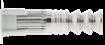
⁃ Waterproof fixings (dams, etc.)
⁃ Fixings for protective barriers, safety rails
* PREMIUM CLEANING:
⁃ 2 blowing with compressed air
⁃ 2 brushing with brushed fitted on a drilling machine
⁃ 2 blowing with compressed air
CHEMICAL RESISTANCE OF THE SPIT RESINS
VIPER XTREM resin: refer to the technical data sheet
EPCON C8 XTREM resin: refer to the technical data sheet
ANCHOR MECHANICAL PROPERTIES SIZE M8 M10 M12 M16 M20 ATP - zinc coated steel fuk [N/mm2] Min. tensile strength 520 520 520 520 520 fyk [N/mm2] Yield strength 420 420 420 420 420 ATP - stainless steel A4 fuk [N/mm2] Min. tensile strength 650 650 650 -fyk [N/mm2] Yield strength 350 350 350 - -
ZINC COATED STEEL
STAINLESS STEEL
TECHNICAL DATA RANGE Min. anchor depth Min. thick. of base material Thread length Depth of threaded start Thread diameter Drilling depth Drilling diameter Total anchor length Tighten torque Code Zinc coated steel Stainless steel A4 (mm) (mm) (mm) (mm) (mm) (mm) (mm) (mm) (Nm) hef hmin l2 LD d hO dO L Tinst M8X60 60 100 20 4,5 8 65 14 60 15 062770 062860 M10X65 65 100 25 7 10 70 20 65 30 062480 062960 M12X75 75 125 30 8 12 75 24 75 70 062760 063100 M12X120 120 180 38 5 12 125 18 120 70 062500M16X125 125 180 40 9,5 16 130 28 125 120 052800 051175 M20X170 170 225 50 12,5 20 175 35 170 200 062810VIPER XTREM cartridge 280 ml 060187 VIPER XTREM cartridge 410 ml 060189 / 060188 VIPER XTREM TR cartridge (Tropical version) 410 ml 060201 EPCON C8 XTREM cartridge 450 ml 055887 l2 LD d0 hmin d hef = L Tinst h0 SETTING TIME VIPER XTREM RESIN TEMPERATURE MAX. TIME FOR INSTALLATION CURING TIME Standard version Tropical version Standard version Tropical version -10°C ‣ -5°C 90 min. - 24 h-4°C ‣ 0°C 50 min. - 240 min.1°C ‣ 5°C 25 min. 60 min. 120 min. 240 min. 6°C ‣ 10°C 15 min. 40 min. 90 min. 180 min. 11°C ‣ 20°C 7 min. 15 min. 60 min. 120 min. 21°C ‣ 30°C 4 min. 8 min. 45 min. 60 min. 31°C ‣ 40°C 2 min. 4 min. 30 min. 60 min. EPCON C8 XTREM RESIN TEMPERATURE MAX. TIME FOR INSTALLATION WAITING TIME FOR 45 % LOAD CURING TIME 5°C 26 min. 15 h 26 h 10°C 20 min. 12 h 23 h 20°C 14 min. 6 h 12 h 30°C 8 min. 5 h 8 h 40°C 5 min. 3 h 6 h x2 x2 x2 INSTALLATION
ATP
75
ZINC COATED & STAINLESS STEEL A4
MINIMUM THICKNESS OF CONCRETE, CHARATERISTIC & MINIMUM DISTANCES FOR SPACING, EDGE
CHARACTERISTIC RESISTANCES [kN]
Characteristic resistances are shown as informative, and have to be used by application of safety factors.
RECOMMENDED LOADS OF ONE ANCHOR WITHOUT INFLUENCE OF SPACING & CONCRETE EDGE
Design resistances for static loads are given for spacing ≥ Scr and edge distance ≥ Ccr For project with reduced spacing and edge distance, we recommend to use SPIT i-Expert software to design your project according to EN 1992-4.
DESIGN RESISTANCE FOR STATIC LOADS IN NON CRACKED
CONCRETE [kN]
SIZE M8 M10 M12 M12 M16 M20 Anchorage depth hef [mm] 60 65 75 120 125 170 Minimum thickness of base material hmin [mm] 100 100 125 180 180 225 Characteristic edge and spacing distance for full anchor capacity Ccr ≥ [mm] 90 97,5 112,5 180 187,5 255 Scr ≥ [mm] 180 195 225 360 375 510 Minimum distances for non-cracked concrete Cmin [mm] 40 45 55 65 65 85 S ≥ [mm] 40 45 55 65 65 85 Smin [mm] 40 45 55 65 65 85 C ≥ [mm] 40 45 55 65 65 85
Recommended values are given for spacing ≥ Scr and edge distance ≥ Ccr
[kN]
Nota: The values indicated in italics and underlined correspond to steel failure SHEAR SIZE M8 M10 M12 M16 M20 M24 hef [mm] 60 65 75 120 125 170 Studs Grade 5.8 7,3 11,6 16,9 16,9 31,4 48,8 VRd,s [kN] ≥C20/25 Studs Grade 8.8 11,6 18,4 26,8 26,8 50,4 78,4 VRd,s [kN] ≥C20/25 Studs Grade A4-70 8,3 12,8 19,2 19,2 35,3 55,1 VRd,s [kN] ≥C20/25 VRd,s = VRk,s /γMS,V Stud grade 5.8 & 8.8 : γMS,V = 1,25 ; Studs Grade A4-70 : γMS,V = 1,56 TENSILE NON-CRACKED CONCRETE ‒ C20/25 SIZE M8 M10 M12 M12 M16 M20 hef [mm] 60 65 75 120 125 170 NRk,p [N/mm2] 16,0 20,0 30,0 30,0 60,0 95,0 SHEAR NON-CRACKED CONCRETE ‒ C20/25 to C50/60 SIZE M8 M10 M12 M12 M16 M20 hef [mm] 60 65 75 120 125 170 Studs Grade 5.8 9,2 14,5 21,1 21,1 39,3 61,0 VRk,s [kN] Studs Grade 8.8 14,5 23,0 33,5 33,5 63,0 98,0 VRk,s [kN] Studs Grade A4-70 13,0 20,0 30,0 30,0 55,0 86,0 VRk,s [kN] TENSILE NON-CRACKED CONCRETE ‒ C20/25 to C50/60 SIZE M8 M10 M12 M12 M16 M20 hef [mm] 60 65 75 120 125 170 NRec [kN] C20/25 7,6 9,5 14,3 14,3 28,6 45,2 NRec [kN] C40/60 9,6 12,0 18,0 18,0 36,0 57,0 NRec = min [NRd,p ; NRd,c; NRd,s] / γF ; γF = 1,4 SHEAR NON-CRACKED CONCRETE ‒ C20/25 to C50/60 SIZE M8 M10 M12 M12 M16 M20 hef [mm] 60 65 75 120 125 170 Studs Grade 5.8 5,2 8,3 12,1 12,1 22,4 34,9 VRec [kN] Studs Grade 8.8 8,3 13,3 19,3 19,3 36,0 56,0 VRec [kN] Studs Grade A4-70 6,0 9,2 13,7 13,7 25,2 39,4 VRec [kN] VRec = VRd,s / γF ; γF = 1,4 TENSILE SIZE M8 M10 M12 M12 M16 M20 hef [mm] 60 65 75 120 125 170 NRd,uncr [kN] C20/25 10,7 13,3 20,0 20,0 40,0 63,3 NRd,uncr [kN] C40/60 13,4 16,8 25,2 25,2 50,4 79,8 Distances Scr and Ccr must be fulfilled NRd,uncr = min[NRk,p,uncr / γMc ; NRk,s / γMs,N] γMC = 1,8 i-Expert Software
76
ATP
ETA
ETA - 13/0435
* ETA - 13/0436
CHARACTERISTICS
⁃ Fixing steel framed structures
⁃ Fixing machinery (resistant to vibration)
⁃ Fixing of storage silos, refinery pipework supports
⁃ Fixing motorway signs
⁃ Fixing safety barriers
* ETA - 13/0436: for post-installed rebars applications
Epoxyacrylate resin for use in non-cracked concrete
These are SPIT Studs, for standard Studs (zinc coated or stainless steel versions) see catalogue.
ANCHOR MECHANICAL PROPERTIES
INSTALLATION
SETTING TIME
SIZE M8 M10 M12 M16 M20 M24 SPIT Studs fuk [N/mm2] Min. tensile strength 600 600 600 600 520 520 fyk [N/mm2] Yield strength 420 420 420 420 420 420 M0Rk,s [Nm] Characteristic bending moment 22 45 79 200 301 520 Studs Grade A4-70 fuk [N/mm2] Min. tensile strength 700 700 700 700 700 700 fyk [N/mm2] Yield strength 350 350 350 350 350 350 M0Rk,s [Nm] Characteristic bending moment 26 52 92 233 454 786
d0 hmin L d hef = h0 df tfix Tinst
APPLICATION
x2 x2 x2
TEMPERATURE MAX. TIME FOR INSTALLATION CURING TIME -5°C ‣ 0°C - 360 min. 0°C ‣ 5°C 18 min. 180 min. 5°C ‣ 10°C 12 min. 90 min. 10°C ‣ 20°C 6 min. 60 min. 20°C ‣ 30°C 4 min. 45 min. 30°C ‣ 40°C 2 min. 35 min. FIELD OF USE Shelf life : 36 months Installation
-5°C / +40°C In-Service
⁃ Range 1: -40°C / +40°C ⁃ Range 2:
40°C /+80°C Installation conditions: ⁃ Category 1: Dry or wet concrete TECHNICAL
RANGE Min. anchor depth Max. thick. of part to be fixed Min. thick of base material Thread diameter Drilling depth Drilling diameter Clearance diameter Total anchor length Tighten torque Code(1) SPIT stud (mm) (mm) (mm) (mm) (mm) (mm) (mm) (mm) (Nm) zinc coated stainless h ef t fix h min d h 0 d 0 df L T inst steel steel A4 M8X110 80 15 110 8 80 10 9 110 10 060215 060222 M10X130 90 20 120 10 90 12 12 130 20 060216 060223 M12X160 110 25 140 12 110 14 14 160 30 060217 060224 M16X190 125 35 160 16 125 18 18 190 60 060218 060225 M20X260 170 65 220 20 170 25 22 260 120 060219 060226 M24X300 210 63 265 24 210 28 26 300 200 060220 060227 MULTI-MAX cartridge 410 ml 060 047 MULTI-MAX cartridge 280 ml 060 040 (1)
temperature:
temperature range:
-
DATA
ZINC COATED STEEL
STAINLESS STEEL
MULTI-MAX 77
Zn
A4
MULTI-MAX
Characteristic resistances are shown as informative, and have to be used by application of safety factors . In tensile loads, the table below shows bond strength in N/mm². All dimensions can be installed with embedment length between 8d to 12d. The characteristic tensile load is determined with the formular :
RECOMMENDED LOADS OF ONE ANCHOR WITHOUT INFLUENCE OF SPACING & CONCRETE EDGE [kN]
Design resistances for static loads are determined from performances given in the ETA, and are guaranteed for spacing ≥ Scr and edge distance ≥ Ccr For project with reduced spacing and edge distance, we recommend to use SPIT i-Expert software to design your project according to EN 1992-4.
DESIGN RESISTANCE FOR STATIC LOADS IN NON CRACKED CONCRETE [kN]
MINIMUM THICKNESS OF CONCRETE, CHARATERISTIC & MINIMUM DISTANCES FOR SPACING, EDGE SIZE M8 M10 M12 M16 M20 M24 Anchorage depth hef [mm] 80 90 110 125 170 210 Minimum thickness of base material hmin [mm] 110 120 140 155 214 262 Characteristic edge and spacing distance for full anchor capacity Ccr ≥ [mm] 120 135 165 187,5 255 315 Scr ≥ [mm] 240 270 330 375 510 630 Minimum distances for non-cracked concrete Cmin [mm] 40 50 60 80 100 120 S ≥ [mm] 40 50 60 80 100 120 Smin [mm] 40 50 60 80 100 120 C ≥ [mm] 40 50 60 80 100 120
N0Rk,p = Π.d hef τRk CHARACTERISTIC RESISTANCES [kN] Recommended values are determined from performances given in the ETA, and are guaranteed for spacing ≥ Scr and edge distance ≥ Ccr
Nota: The values indicated in italics and underlined correspond to steel failure SHEAR SIZE M8 M10 M12 M16 M20 M24 hef [mm] 80 90 110 125 170 210 SPIT Studs 7,2 12,0 16,8 31,2 48,8 70,4 VRd,s [kN] ≥C20/25 Studs Grade A4-70 8,3 12,8 19,2 35,3 55,1 79,5 VRd,s [kN] ≥C20/25 VRd,s = VRk,s /γMS,V SPIT Studs : γMS,V = 1,25 ; Studs Grade A4-70 : γMS,V = 1,56 TENSILE SIZE M8 M10 M12 M16 M20 M24 hef [mm] 80 90 110 125 170 210 SPIT Studs 10,1 14,1 19,6 27,9 47,5 66,0 NRd,uncr [kN] C20/25 Studs Grade A4-70 10,1 14,1 19,6 27,9 47,5 66,0 NRd,uncr [kN] C20/25 Distances Scr and Ccr must be fulfilled NRd,uncr = min[NRk,p,uncr / γMc ; NRk,s / γMs,N] γMC = 1,8 ; SPIT Studs : γMS,N = 1,5 ; Studs Grade A4-70 : γMS,N = 1,87 TENSILE NON-CRACKED CONCRETE ‒ C20/25 SIZE M8 M10 M12 M16 M20 M24 hef min [mm] 64 80 96 128 160 192 hef max [mm] 96 120 144 192 240 288 τRk,uncr [N/mm2] 9,0 9,0 8,5 8,0 8,0 7,5 SHEAR NON-CRACKED CONCRETE ‒ C20/25 to C50/60 SIZE M8 M10 M12 M16 M20 M24 hef min [mm] 64 80 96 128 160 192 hef max [mm] 96 120 144 192 240 288 SPIT Studs 9,2 15,0 21,0 39,0 61,0 88,0 VRks [kN] Studs Grade A4-70 13,0 20,0 30,0 55,0 86,0 124,0 VRks [kN] TENSILE NON-CRACKED CONCRETE ‒ C20/25 SIZE M8 M10 M12 M16 M20 M24 hef [mm] 80 90 110 125 170 210 SPIT Studs 7,2 10,1 14,0 19,9 33,9 47,1 NRec [kN] Studs Grade A4-70 7,2 10,1 14,0 19,9 33,9 47,1 NRec [kN] NRec = min [NRd,p ; NRd,c; NRd,s] / γF ; γF = 1,4 SHEAR NON-CRACKED CONCRETE ‒ C20/25 to C50/60 SIZE M8 M10 M12 M16 M20 M24 hef [mm] 80 90 110 125 170 210 SPIT Studs 5,1 8,6 12,0 22,3 34,9 50,3 VRec [kN] Studs Grade A4-70 6,0 9,2 13,7 25,2 39,4 56,8 VRec [kN] VRec = VRd,s / γF ; γF = 1,4
i-Expert Software
78
Epoxyacrylate resin for fixing in hollow masonry
For sleeves and studs code numbers, see catalogue (1) 2Nm in clay masonry OPTIBRIC PV3+ and in hollow concrete block * Shelf life : 36 months
CHARATERISTIC & MINIMUM DISTANCES FOR SPACING, EDGE
ID-ALL Tinst d0 h0 d L hef tfix Ls SLEEVE d0 h0 Tinst d Ls L hef tfix ETA - 13/0437 ETA
⁃ Signs ⁃ Scaffolding ⁃ Electrical switchboards ⁃ Radiators ⁃ Air conditioning ducts ⁃ Rail guard
⁃ Blinds ⁃ Climbing walls ⁃ Metal scale ⁃ Hand rails ⁃ Pole and ducts ⁃ Demountable partitions ⁃ Kitchen furniture
TECHNICAL DATA RANGE Minimum anchor depth Drilling depth Drilling diameter Thread diameter Minimum stud length External diameter ID-ALL/SLEEVE Total length ID-ALL/SLEEVE Tighten torque (mm) (mm) (mm) (mm) (mm) (mm) (mm) (Nm) h ef h 0 d 0 d L d nom L s T inst ID-ALL + stud M8 65 70 16 8 76 + tfix 16 70 3(1) ID-ALL + stud M10 65 70 16 10 78 + tfix 16 70 3(1) Sleeve Ø15 + stud M8 130 135 15 8 138 + tfix 15 130 3(1) Sleeve Ø15 + stud M10 130 135 15 10 140 + tfix 15 130 3(1) Sleeve Ø20 + stud M12 85 90 20 12 98 + tfix 20 85 3(1) MULTI-MAX cartridge 410 ml * 060047 MULTI-MAX cartridge 280 ml * 060040
returns
APPLICATION
SIZE M8 M10 M12 M8/M10 SLEEVE 15X130 15X130 20X85 ID-ALL HOLLOW CLAY BRICK (fb > 12 N/mm²) Cmin = Ccr [mm] 100 100 100 100 Smin = Scr [mm] 200 200 200 200 HOLLOW CONCRETE BLOCK (fb > 4 N/mm²) Cmin = Ccr [mm] 100 100 100 100 Smin = Scr [mm] 200 200 200 200 SETTING TIME TEMPERATURE MAX. TIME FOR INSTALLATION CURING TIME -5°C ‣ 0°C - 360 min. 0°C ‣ 5°C 18 min. 180 min. 5°C ‣ 10°C 12 min. 90 min. 10°C ‣ 20°C 6 min. 60 min. 20°C ‣ 30°C 4 min. 45 min. 30°C ‣ 40°C 2 min. 35 min. CHARACTERISTICS ZINC COATED STEEL Zn MASONRIES INSTALLATION MULTI-MAX 79
MULTI-MAX
CHARACTERISTIC RESISTANCES [kN]
Characteristic resistances are shown as informative, and have to be used by application of safety factors.
RECOMMENDED LOADS OF ONE ANCHOR WITHOUT INFLUENCE OF SPACING & CONCRETE EDGE [kN]
Recommended values are determined from performances given in the ETA, and are guaranteed for spacing ≥ Scr and edge distance ≥ Ccr
Design resistances for static loads are determined from performances given in the ETA, and are guaranteed for spacing ≥ Scr and edge distance ≥ Ccr For project with reduced spacing and edge distance, we recommend to use SPIT i-Expert software to design your project.
DESIGN RESISTANCE FOR STATIC LOADS IN MASONRIES [kN]
TENSILE MASONRIES SIZE ID-ALL SLEEVE Ø20X80 Ø15X130 M8 M10 M12 M8 M10 Hollow concrete block B40 (fb ≥ 6,0 N/mm²) NRd [kN] 0,76 0,57 0,57 Hollow clay brick Optibric PV 3+ (fb ≥ 9,0 N/mm²) NRd [kN] 0,57 0,94 0,57 Hollow clay brick Porotherm GF R20 Th+ (fb ≥ 9,0 N/mm²) NRd [kN] 0,33 0,94 0,45 Hollow clay brick Porotherm GF R37 Th+ (fb ≥ 9,0 N/mm²) NRd [kN] 0,45 0,33 0,76 Calcium silicate masonries KSL-R (P) 240 (fb ≥ 9,0 N/mm²) NRd [kN] 0,57 1,33 1,14 TENSILE MASONRIES SIZE ID-ALL SLEEVE Ø20X80 Ø15X130 M8 M10 M12 M8 M10 Hollow concrete block B40 (fb ≥ 6,0 N/mm²) NRk [kN] 2,28 1,75 1,72 Hollow clay brick Optibric PV 3+ (fb ≥ 9,0 N/mm²) NRk [kN] 1,72 2,84 1,72 Hollow clay brick Porotherm GF R20 Th+ (fb ≥ 9,0 N/mm²) NRk [kN] 1,00 2,84 1,36 Hollow clay brick Porotherm GF R37 Th+ (fb ≥ 9,0 N/mm²) NRk [kN] 1,36 1,00 2,28 Calcium silicate masonries KSL-R (P) 240 (fb ≥ 9,0 N/mm²) NRk [kN] 1,72 4,00 3,44
SHEAR MASONRIES SIZE ID-ALL SLEEVE Ø20X80 Ø15X130 M8 M10 M12 M8 M10 Hollow concrete block B40 (fb ≥ 6,0 N/mm²) VRk [kN] 2,84 2,28 3,44 Hollow clay brick Optibric PV 3+ (fb ≥ 9,0 N/mm²) VRk [kN] 1,72 4,00 1,36 Hollow clay brick Porotherm GF R20 Th+ (fb ≥ 9,0 N/mm²) VRk [kN] 4,56 3,44 4,00 Hollow clay brick Porotherm GF R37 Th+ (fb ≥ 9,0 N/mm²) VRk [kN] 1,00 4,56 1,72 Calcium silicate masonries KSL-R (P) 240 (fb ≥ 9,0 N/mm²) VRk [kN] 10,28 12,56 11,40 10,28 13,72 TENSILE MASONRIES SIZE ID-ALL SLEEVE Ø20X80 Ø15X130 M8 M10 M12 M8 M10 Hollow concrete block B40 (fb ≥ 6,0 N/mm²) NRec [kN] 0,57 0,43 0,43 Hollow clay brick Optibric PV 3+ (fb ≥ 9,0 N/mm²) NRec [kN] 0,43 0,71 0,43 Hollow clay brick Porotherm GF R20 Th+ (fb ≥ 9,0 N/mm²) NRec [kN] 0,25 0,71 0,34 Hollow clay brick Porotherm GF R37 Th+ (fb ≥ 9,0 N/mm²) NRec [kN] 0,34 0,25 0,57 Calcium silicate masonries KSL-R (P) 240 (fb ≥ 9,0 N/mm²) NRec [kN] 0,43 1,00 0,86 γF = 1,4 ; γM = 2,4 SHEAR MASONRIES SIZE ID-ALL SLEEVE Ø20X80 Ø15X130 M8 M10 M12 M8 M10 Hollow concrete block B40 (fb ≥ 6,0 N/mm²) VRec [kN] 0,71 0,57 0,86 Hollow clay brick Optibric PV 3+ (fb ≥ 9,0 N/mm²) VRec [kN] 0,43 1,00 0,34 Hollow clay brick Porotherm GF R20 Th+ (fb ≥ 9,0 N/mm²) VRec [kN] 1,14 0,86 1,00 Hollow clay brick Porotherm GF R37 Th+ (fb ≥ 9,0 N/mm²) VRec [kN] 0,25 1,14 0,43 Calcium silicate masonries KSL-R (P) 240 (fb ≥ 9,0 N/mm²) VRec [kN] 2,57 3,14 2,85 2,57 3,43 γF = 1,4 ; γM = 2,4
SHEAR MASONRIES SIZE ID-ALL SLEEVE Ø20X80 Ø15X130 M8 M10 M12 M8 M10 Hollow concrete block B40 (fb ≥ 6,0 N/mm²) VRd [kN] 0,94 0,76 1,14 Hollow clay brick Optibric PV 3+ (fb ≥ 9,0 N/mm²) VRd [kN] 0,57 1,33 0,45 Hollow clay brick Porotherm GF R20 Th+ (fb ≥ 9,0 N/mm²) VRd [kN] 1,52 1,14 1,33 Hollow clay brick Porotherm GF R37 Th+ (fb ≥ 9,0 N/mm²) VRd [kN] 0,33 1,52 0,57 Calcium silicate masonries KSL-R (P) 240 (fb ≥ 9,0 N/mm²) VRd [kN] 3,42 4,18 3,79 3,42 4,56
i-Expert Software
80
Polyester resin for fixing in concrete and hollow and solid masonries
(1) Plastic sleeve Ø15X85 for male studs M8 and M10 in hollow material. Plastic sleeve Ø15X130 for threaded stud M8X170 - Using standard threaded rods.
sleeve Ø20X85 for male studs M12 and female studs M8 and M10 in hollow material.
⁃ Signs ⁃ Scaffolding ⁃ Electrical switchboards ⁃ Radiators ⁃ Air conditioning ducts ⁃ Rail guard returns ⁃ Blinds ⁃ Climbing walls ⁃ Metal scale ⁃ Hand rails ⁃ Pole and ducts ⁃ Demountable partitions ⁃ Kitchen furniture APPLICATION TECHNICAL DATA VERSION RANGE Minimum anchor depth Drilling depth Drilling diameter Thread / Sleeve diameter Thread length Stud / Sleeve length Maxi. thick. of part to be fixed Tighten torque Code Hollow Solid Hollow Solid (mm) (mm) (mm) (mm) (mm) (mm) (mm) (mm) (Nm) h ef h 0 h 0 d 0 d 0 d /d nom d L / L s t fix T inst MALE STUDS M8X100 75 80 75 15 10 8 - 100 12 5 061650 M10X100 75 80 75 16 10 - 100 20 8 061660 M12X100 75 80 75 16 12 - 100 20 8 061670 F EMALE STUDS M8X58 58 80 58 8 20 58 - 8 061740 M10X58 58 80 58 10 23 58 - 8 061750 SLEEVES (1) Ø15X85 - 90 15 15 - 85 - - 557070 Ø15X130 - 135 15 15 - 130 - - 557080 Ø20X85 - 90 20 20 - 85 - - 557090 THREADED STUDS M8X110 80 - 80 - 10 8 - 110 15 10 055800 M10X130 90 - 90 - 12 10 - 130 20 20 055801 M12X160 110 - 110 - 14 12 - 160 25 30 055802 M16X190 125 - 125 - 18 16 - 190 35 60 055803 C-MIX PLUS (grey) cartridge 380 ml* 055881 C-MIX PLUS (stone) cartridge 380 ml* 055882 C-MIX PLUS (grey) cartridge 300 ml* 055866 C-MIX PLUS (stone) cartridge 300 ml* 055865 * Shelf life : 36 months
SETTING TIME TEMPERATURE MAX. TIME FOR INSTALLATION CURING TIME cartridge 300 ml cartridge 380 ml cartridge 300 ml cartridge 380 ml -5°C ‣ 0°C 40 min. - 180 min.0°C ‣ 10°C 20 min. 10 min. 90 min. 75 min. 10°C ‣ 20°C 9 min. 4 min. 60 min. 40 min. 20°C ‣ 30°C 5 min. 2 min. 30 min. 25 min. 30°C ‣ 40°C 3 min. 1 min. 20 min. 20 min. CHARACTERISTICS ZINC COATED STEEL Zn MASONRIES INSTALLATION l2 d0 d Ls L hef = h0 tfix Tinst d dnom L = hef x2 x2 x2 Technical Assessment SOCOTEC N°18056808000007
81
Plastic
C-MIX PLUS
CHARATERISTIC
DISTANCES FOR SPACING, EDGE
resistances are shown as informative, and have to be used by application of safety factors. CHARACTERISTIC
RECOMMENDED LOADS OF ONE ANCHOR WITHOUT INFLUENCE OF SPACING & CONCRETE EDGE [kN]
SHEAR
SHEAR NON-CRACKED CONCRETE ‒ C20/25 SIZE M8* M10* M12* M16* VRk [kN] 11,4 18,4 26,6 50,4 * Threaded stud MASONRIES SIZE SLEEVE + MALE STUD SLEEVE + FEMALE STUD SLEEVE M15X130 M8 M10 M12 M8 M10 M12 STUD* M8 Solid clay bricks BP 400 VRk [kN] 7,2 10,0 16,0 8,0 10,0 16,0Solid concrete blocks B80 VRk [kN] 7,2 8,8 12,8 7,2 8,8 12,8Hollow clay bricks C40 rendered VRk [kN] 8,0 8,0 2,4 Hollow clay bricks C40 not rendered VRk [kN] 5,2 5,2 5,2 Hollow concrete blocks B40 rendered VRk [kN] 8,0 8,0 8,0 Hollow concrete blocks B40 rendered VRk [kN] 7,2 7,2 7,2 * Sleeve Ø15X130 + threaded stud M8X170 TENSILE NON-CRACKED CONCRETE ‒ C20/25 SIZE M8* M10* M12* M16* NRk [kN] 17,9 25,2 37,0 56,0 * Threaded stud MASONRIES SIZE SLEEVE + MALE STUD SLEEVE + FEMALE STUD SLEEVE M15X130 M8 M10 M12 M8 M10 M12 STUD* M8 Solid clay bricks BP 400 NRk [kN] 5,2 5,2Solid concrete blocks B80 NRk [kN] 20,0 20,0Hollow clay bricks C40 rendered NRk [kN] 4,0 4,0 2,4 Hollow clay bricks C40 not rendered NRk [kN] 2,4 2,4 2,4 Hollow concrete blocks B40 rendered NRk [kN] 6,4 6,4 4,0 Hollow concrete blocks B40 rendered NRk [kN] 3,6 3,6 3,6 * Sleeve Ø15X130 + threaded stud M8X170
RESISTANCES [kN] Recommended values are given for spacing ≥ Scr and edge distance ≥ Ccr
Characteristic
SIZE - THREADED STUD M8 M10 M12 M16 NON-CRACKED CONCRETE Cmin = Ccr [mm] 80 90 110 125 Smin = Scr [mm] 160 180 220 250 SIZE - SLEEVE 15X85 15X85 20X85SOLID CLAY BRICK Cmin = Ccr [mm] 80 90 110 125 Smin = Sc [mm] 160 180 220 250 HOLLOW CLAY BRICK Cmin = Ccr [mm] 100 100 100 100 Smin = Scr [mm] 200 200 200 200 HOLLOW CONCRETE BLOCK Cmin = Ccr [mm] 100 100 100 100 Smin = Scr [mm] 200 200 200 200
NON-CRACKED CONCRETE ‒ C20/25 SIZE M8* M10* M12* M16* NRec [kN] 4,5 6,3 9,3 14,0 * Threaded stud MASONRIES SIZE SLEEVE + MALE STUD SLEEVE + FEMALE STUD SLEEVE M15X130 M8 M10 M12 M8 M10 M12 STUD* M8 Solid clay bricks BP 400 NRec [kN] 1,3 1,3Solid concrete blocks B80 NRec [kN] 5,0 5,0Hollow clay bricks C40 rendered NRec [kN] 1,0 1,0 0,6 Hollow clay bricks C40 not rendered NRec [kN] 0,6 0,6 0,6 Hollow concrete blocks B40 rendered NRec [kN] 1,6 1,6 1,0 Hollow concrete blocks B40 rendered NRec [kN] 0,9 0,9 0,9 * Sleeve Ø15X130 + threaded stud M8X170
& MINIMUM
TENSILE
CONCRETE ‒ C20/25 SIZE M8* M10* M12* M16* VRec [kN] 2,9 4,6 6,7 12,6 * Threaded stud MASONRIES SIZE SLEEVE + MALE STUD SLEEVE + FEMALE STUD SLEEVE M15X130 M8 M10 M12 M8 M10 M12 STUD* M8 Solid clay bricks BP 400 VRec [kN] 1,8 2,5 4,0 2,0 2,5 4,0Solid concrete blocks B80 VRec [kN] 1,8 2,2 3,2 1,8 2,2 3,2Hollow clay bricks C40 rendered VRec [kN] 2,0 2,0 0,6 Hollow clay bricks C40 not rendered VRec [kN] 1,3 1,3 1,3 Hollow concrete blocks B40 rendered VRec [kN] 2,0 2,0 2,0 Hollow concrete blocks B40 rendered VRec [kN] 1,8 1,8 1,8 * Sleeve Ø15X130 + threaded stud M8X170
82
NON-CRACKED
C-MIX PLUS
Design resistances for static loads are given for spacing ≥ Scr and edge distance ≥ Ccr For project with reduced spacing and edge distance, we recommend to use SPIT i-Expert software to design your project according to EN 1992-4.
DESIGN RESISTANCE FOR STATIC LOADS IN NON-CRACKED CONCRETE [kN]
DESIGN RESISTANCE FOR STATIC LOADS IN MASONRIES [kN]
TENSILE MASONRIES SIZE SLEEVE + MALE STUD SLEEVE + FEMALE STUD SLEEVE M15X130 M8 M10 M12 M8 M10 M12 STUD* M8 Solid clay bricks BP 400 NRd [kN] 1,7 1,7Solid concrete blocks B80 NRd [kN] 6,7 6,7Hollow clay bricks C40 rendered NRd [kN] 1,3 1,3 0,8 Hollow clay bricks C40 not rendered NRd [kN] 0,8 0,8 0,8 Hollow concrete blocks B40 rendered NRd [kN] 2,1 2,1 1,3 Hollow concrete blocks B40 rendered NRd [kN] 1,2 1,2 1,2 * Sleeve Ø15X130 + threaded stud M8X170 SHEAR MASONRIES SIZE SLEEVE + MALE STUD SLEEVE + FEMALE STUD SLEEVE M15X130 M8 M10 M12 M8 M10 M12 STUD* M8 Solid clay bricks BP 400 VRd [kN] 2,4 3,3 5,3 2,7 3,3 5,3Solid concrete blocks B80 VRd [kN] 2,4 2,9 4,3 2,4 2,9 4,3Hollow clay bricks C40 rendered VRd [kN] 2,7 2,7 0,8 Hollow clay bricks C40 not rendered VRd [kN] 1,7 1,7 1,7 Hollow concrete blocks B40 rendered VRd [kN] 2,7 2,7 2,7 Hollow concrete blocks B40 rendered VRd [kN] 2,4 2,4 2,4 * Sleeve Ø15X130 + threaded stud M8X170
TENSILE NON-CRACKED CONCRETE ‒ C20/25 SIZE M8* M10* M12* M16* NRd [kN] 6,0 8,4 12,3 18,6 * Threaded stud SHEAR NON-CRACKED CONCRETE ‒ C20/25 SIZE M8* M10* M12* M16* VRd [kN] 3,8 6,1 8,8 16,8 * Threaded stud i-Expert Software C-MIX PLUS 83
Hybrid anchor, with vinylester resin for fixing in concrete and hollow and solid masonries
CHARACTERISTICS
CHARATERISTIC & MINIMUM DISTANCES FOR SPACING, EDGE
M8X140-Ø16
⁃ Wall-mounted boiler
⁃ Hand rails
⁃ Bracketing
M10X140-Ø16
⁃ Water heaters
⁃ Electrical switchboards
⁃ Sink
M10X140-Ø16 EXT.
⁃ Air conditioning brackets
⁃ Facade lighting
⁃ Signs
APPLICATION SETTING TIME TEMPERATURE CURING TIME 5°C 90 min. 15°C 60 min. 25°C 45 min. 35°C 30 min.
ZINC COATED STEEL Zn MASONRIES x2 x2 x2 INSTALLATION TECHNICAL DATA RANGE EASYMIX Male stud Drilling Ø Drilling depth Max. thick. part to be fixed Max. tighten torque Code External Ø Total length Thread Ø Total length Thread length Masonry Concrete (mm) (mm) (mm) (mm) (mm) (mm) (mm) (mm) (Nm) (Nm) Blister Box dnom LS d L Lf dO hO tfix Tinst Tinst x4 x12 M8X140-Ø16 8 060230 060228 M10X140-Ø16 16 135 10 180 40 16 150 30 3 10 060231 060229 M10X140-Ø16 EXT* 10 060232* OUTDOOR version, supplied with zinc flake coating (5µm) male studs for external application T25 Tinst d0 h0 dL tfix Ls Lf dnom Technical Assessment SOCOTEC N°180468080000010
SIZE M8/M10 NON-CRACKED CONCRETE Cmin = Ccr [mm] 80 Smin = Scr [mm] 160 HOLLOW CLAY BRICK Cmin = Ccr [mm] 100 Smin = Scr [mm] 200 HOLLOW CONCRETE BLOCK Cmin = Ccr [mm] 100 Smin = Scr [mm] 200 PRE-DOSED SYSTEM : VINYLESTER RESIN* *Shelf life : 36 months
84
EASYMIX
CHARACTERISTIC RESISTANCES [kN]
Characteristic resistances are shown as informative, and have to be used by application of safety factors.
TENSILE NON-CRACKED CONCRETE ‒ C20/25
concrete block B40 (fb ≥ 6,0 N/mm²)
Hollow clay brick Optibric PV 3+ (fb ≥ 9,0 N/mm²)
Hollow clay brick Porotherm GF R20 Th+ (fb ≥ 10,0 N/mm²)
Hollow clay brick Porotherm GF R37 Th+ (fb ≥ 8,0 N/mm²)
SHEAR
NON-CRACKED CONCRETE ‒ C20/25 to C50/60
Hollow concrete block B40 (fb ≥ 6,0 N/mm²)
VRk [kN] 7,2
Hollow clay brick Optibric PV 3+ (fb ≥ 9,0 N/mm²)
VRk [kN] 5,2
Hollow clay brick Porotherm GF R20 Th+ (fb ≥ 10,0 N/mm²)
VRk [kN]
Hollow clay brick Porotherm GF R37 Th+ (fb ≥ 8,0 N/mm²)
RECOMMENDED LOADS OF ONE ANCHOR WITHOUT INFLUENCE OF SPACING & CONCRETE EDGE [kN]
Recommended values are given for spacing ≥ Scr and edge distance ≥ Ccr
TENSILE NON-CRACKED CONCRETE ‒ C20/25 SIZE M8/M10 NRec [kN] 2,5 MASONRIES SIZE M8/M10 Hollow concrete block B40 (fb ≥ 6,0 N/mm²) NRec [kN] 0,65 Hollow clay brick Optibric PV 3+ (fb ≥ 9,0 N/mm²) NRec [kN] 0,40 Hollow clay brick Porotherm GF R20 Th+ (fb ≥ 10,0 N/mm²) NRec [kN] 0,40 Hollow clay brick Porotherm GF R37 Th+ (fb ≥ 8,0 N/mm²) NRec [kN] 0,40 NRec = NRd / γF ; γF = 1,4 SHEAR NON-CRACKED CONCRETE ‒ C20/25 to C50/60 SIZE M8/M10 VRec [kN] 2,5 MASONRIES SIZE M8/M10 Hollow concrete block B40 (fb ≥ 6,0 N/mm²) VRec [kN] 1,80 Hollow clay brick Optibric PV 3+ (fb ≥ 9,0 N/mm²) VRec [kN] 1,30 Hollow clay brick Porotherm GF R20 Th+ (fb ≥ 10,0 N/mm²) VRec [kN] 1,30 Hollow clay brick Porotherm GF R37 Th+ (fb ≥ 8,0 N/mm²) VRec [kN] 1,30 VRec = VRd / γF ; γF = 1,4
SIZE M8/M10 NRk [kN] 10,0 MASONRIES SIZE M8/M10
NRk [kN] 2,6
NRk [kN] 1,6
NRk
1,6
NRk
Hollow
[kN]
[kN] 1,6
SIZE M8/M10 VRk
10,0 MASONRIES SIZE M8/M10
[kN]
5,2
5,2 EASYMIX 85
VRk [kN]
Design resistances for static loads are given for spacing ≥ Scr and edge distance ≥ Ccr For project with reduced spacing and edge distance, we recommend to use SPIT i-Expert software to design your project.
DESIGN RESISTANCE FOR STATIC LOADS IN NON-CRACKED CONCRETE [kN]
DESIGN RESISTANCE FOR STATIC LOADS IN MASONRIES [kN]
concrete block B40 (fb ≥ 6,0 N/mm²)
clay brick Optibric PV 3+ (fb ≥ 9,0 N/mm²)
clay brick Porotherm GF R20 Th+ (fb ≥ 10,0 N/mm²)
clay brick Porotherm GF R37 Th+ (fb ≥ 8,0 N/mm²)
TENSILE SIZE M8/M10 NRd [kN] C20/25 3,3 Distances Scr and Ccr must be fulfilled NRd = NRk,p / γMc γMc = 2,1 SHEAR SIZE M8/M10 VRd [kN] ≥ C20/25 3,3 VRd = VRk / γMc γMc = 2,1 TENSILE SIZE M8/M10 Hollow
NRd [kN] 0,9 Hollow
NRd [kN] 0,5 Hollow
NRd [kN] 0,5 Hollow
NRd [kN] 0,5 Distances Scr and Ccr must be fulfilled NRd = NRk,p / γMc γMc = 2,1 SHEAR SIZE M8/M10 Hollow
VRd [kN] 2,4 Hollow
VRd [kN] 1,7 Hollow
VRd [kN] 1,7 Hollow clay
Porotherm
VRd [kN] 1,7 VRd =
γMc γMc = 2,1
concrete block B40 (fb ≥ 6,0 N/mm²)
clay brick Optibric PV 3+ (fb ≥ 9,0 N/mm²)
clay brick Porotherm GF R20 Th+ (fb ≥ 10,0 N/mm²)
brick
GF R37 Th+ (fb ≥ 8,0 N/mm²)
VRk /
86
i-Expert
Software EASYMIX
Universal frame fixing for concrete, in hollow and solid masonries
MINIMUM THICKNESS OF CONCRETE, CHARATERISTIC & MINIMUM DISTANCES FOR SPACING, EDGE
SIZE Ø10 Ø12 Ø16 Anchor depth hef [mm] 70 70 90 Minimum thickness of base material hmin [mm] 140 200 200 Characteristic edge and spacing distance for full anchor capacity NON CRACKED CONCRETE Ccr ≥ [mm] 70 70 70 Scr ≥ [mm] 140 140 140 MASONRIES Ccr ≥ [mm] 70 70 70 Scr ≥ [mm] 140 140 140 Minimum distances NON CRACKED CONCRETE Cmin [mm] 60 60 60 Smin [mm] 50 50 50 SOLID MASONRIES Cmin [mm] 60 60 60 Smin [mm] 50 50 50 HOLLOW MASONRIES Cmin [mm] 105 105 105 Smin [mm] 200 200 200 MASONRIES
⁃ Roofing clamps ⁃ Sanitary equipement ⁃ Fixing wall plates ⁃ Timbers APPLICATION TECHNICAL DATA RANGE Min. anchor depth Max.thick of part to be fixed (1) Anchor external diameter Drilling depth through part Drilling depth in base material Drilling diameter Min. thick of base material Total sleeve length Tighten torque Code Head version F Head version H (mm) (mm) (mm) (mm) (mm) (mm) (mm) (mm) (mm) h ef t fix d nom L3 h 0 d 0 h min L T inst 10X80/10 70 10 10 80 80 10 140 80 10 56665310X100/30 30 110 100 566654 10X115/45 45 125 115 566655 10X145/75 75 155 145 566656 10X160/90 90 170 160 566657 10X185/115 115 195 185 566658 10X210/140 140 220 210 566659 12X120/50 70 50 12 135 85 12 200 120 10566675 12X145/75 75 160 145 566676 12X165/95 95 180 165 566677 12X185/115 115 200 185 566678 12X210/140 140 225 210 566679 16X145/55 90 55 16 165 110 16 200 145 20566680 16X165/75 75 185 165 566681 16X185/95 95 205 185 566682 16X200/110 110 220 200 566683 16X240/150 150 260 240 566428 16X270180 180 290 270 566484 Ø12 and Ø16: do not belong to ATE
ZINC COATED STEEL Zn ETE - 17/0202 ETE INSTALLATION Tinst d0 = dnom hmin h0 L tfix hef L3 F : Countersunk head TORX 40 (Ø10) HS : Hexagonal head + large washer for Ø12 & Ø16 Ø10: Sw = 13 mm Ø12: Sw = 17 mm Ø16: Sw = 19 mm PROLONG 87
CHARACTERISTICS
PROLONG
CHARACTERISTIC RESISTANCES [kN]
Characteristic resistances are shown as informative, and have to be used by application of safety factors.
RECOMMENDED LOADS OF ONE ANCHOR WITHOUT INFLUENCE OF SPACING & CONCRETE EDGE [kN]
Recommended values are determined from performances given in the ETA, and are guaranteed for spacing ≥ Scr and edge distance ≥
Design resistances for static loads are determined from performances given in the ETA, and are guaranteed for spacing ≥ Scr and edge distance ≥ Ccr For project with reduced spacing and edge distance, we recommend to use SPIT i-Expert software to design your project.
DESIGN RESISTANCE FOR STATIC LOADS [kN]
TENSILE NON-CRACKED CONCRETE ‒ C20/25 SIZE Ø10 Ø12 Ø16 hef [mm] 70 70 90 NRk [kN] 2,8 4,5 6,3 MASONRIES SIZE Ø10 Ø12 Ø16 hef [mm] 70 70 90 Clay bricks (fb = 55 N/mm²) NRk [kN] 3,2 4,2 6,0 Hollow concrete blocks B40 not rendered (fb = 6,5 N/mm²) NRu,m [kN] 0,8 1,26 2,4 Hollow clay bricks not rendered (fb = 4,5 N/mm²) NRk [kN] 0,8 0,6 0,6 Aerated concrete (Mvn = 500 kg/m3) NRk [kN] 0,7 1,1 1,4
C
SHEAR NON-CRACKED CONCRETE ‒ C20/25 SIZE Ø10 Ø12 Ø16 hef [mm] 70 70 90 VRk [kN] 2,8 7,1 14,4 MASONRIES SIZE Ø10 Ø12 Ø16 hef [mm] 70 70 90 Clay bricks (fb = 55 N/mm²) VRk [kN] 3,2 6,4 13,9 Hollow concrete blocks B40 not rendered (fb = 6,5 N/mm²) VRk [kN] 0,8 1,9 2,7 Hollow clay bricks not rendered (fb = 4,5 N/mm²) VRk [kN] 0,8 2,0 2,9 Aerated concrete (Mvn = 500 kg/m3) VRk [kN] - -TENSILE NON-CRACKED CONCRETE ‒ C20/25 SIZE Ø10 Ø12 Ø16 hef [mm] 70 70 90 NRec [kN] 1,00 1,56 2,20 MASONRIES SIZE Ø10 Ø12 Ø16 hef [mm] 70 70 90 Clay bricks (fb = 55 N/mm²) NRec [kN] 1,15 1,48 2,08 Hollow concrete blocks B40 not rendered (fb = 6,5 N/mm²) NRec [kN] 0,28 0,44 0,84 Hollow clay bricks not rendered (fb = 4,5 N/mm²) NRec [kN] 0,28 0,24 0,24 Aerated concrete (Mvn = 500 kg/m3) NRec [kN] 0,25 0,38 0,52 SHEAR NON-CRACKED CONCRETE ‒ C20/25 SIZE Ø10 Ø12 Ø16 hef [mm] 70 70 90 VRec [kN] 1,00 2,50 5,40 MASONRIES SIZE Ø10 Ø12 Ø16 hef [mm] 70 70 90 Clay bricks (fb = 55 N/mm²) VRec [kN] 1,15 2,24 4,86 Hollow concrete blocks B40 not rendered (fb = 6,5 N/mm²) VRec [kN] 0,28 0,70 0,84 Hollow clay bricks not rendered (fb = 4,5 N/mm²) VRec [kN] 0,28 0,70 1,02 Aerated concrete (Mvn = 500 kg/m3) VRec [kN] - - -
cr
TENSILE NON-CRACKED CONCRETE ‒ C20/25 SIZE Ø10 Ø12 Ø16 hef [mm] 70 70 90 NRd [kN] 1,40 2,23 3,14 MASONRIES SIZE Ø10 Ø12 Ø16 hef [mm] 70 70 90 Clay bricks (fb = 55 N/mm²) NRd [kN] 1,60 2,10 3,00 Hollow concrete blocks B40 not rendered
N/mm²) NRd [kN] 0,40 0,63 1,20 Hollow clay bricks not rendered (fb = 4,5 N/mm²) NRd [kN] 0,40 0,30 0,30 Aerated concrete (Mvn = 500 kg/m3) NRd [kN] 0,35 0,54 0,74 SHEAR NON-CRACKED CONCRETE ‒ C20/25 SIZE Ø10 Ø12 Ø16 hef [mm] 70 70 90 VRd [kN] 1,40 3,57 7,71 MASONRIES SIZE Ø10 Ø12 Ø16 hef [mm] 70 70 90 Clay bricks (fb = 55 N/mm²) VRd [kN] 1,60 3,20 6,94
VRd [kN] 0,40 0,97 1,37
clay
VRd [kN] 0,40 1,00 1,45
VRd [kN]
-
(fb = 6,5
Hollow concrete blocks B40 not rendered (fb = 6,5 N/mm²)
Hollow
bricks not rendered (fb = 4,5 N/mm²)
Aerated concrete (Mvn = 500 kg/m3)
- -
i-Expert Software
88
B-LONG XTREM
Frame anchor for fixings in concrete, solid masonry, hollow block and aerated concrete
CARACTÉRISTIQUES TECHNIQUES
MINIMUM THICKNESS OF CONCRETE, CHARATERISTIC & MINIMUM DISTANCES FOR SPACING, EDGE
⁃
clamps ⁃
wall plates ⁃ Timbers ⁃ Insulation ⁃
bracketing APPLICATION Tinst d0 hmin h0 L tfix hnom STAINLESS STEEL A4 MASONRIES CHARACTERISTICS ZINC COATED STEEL Zn
Roofing
Sanitary equipement ⁃ Fixing
Facade
SIZE Ø8 Ø10 Ø10 Anchor depth hnom [mm] 50 40 50 Minimum thickness of concrete hmin [mm] 100 80 100 Characteristic edge and spacing distance for full anchor capacity NON CRACKED CONCRETE Ccr ≥ [mm] 50 80 100 Scr ≥ [mm] 60 65 90 MASONRIES Ccr ≥ [mm] 100 100 100 Scr ≥ [mm] 200 200 200 Minimum distances NON CRACKED CONCRETE Cmin [mm] 50 50 60 Smin [mm] 50 60 70 MASONRIES Cmin [mm] 100 100 100 Smin [mm] 200 200 200 F : Countersunk head TORX 30 (Ø8) TORX 40 (Ø10) HS : Hexagonal head + integrated washer INSTALLATION
GAMME Concrete Structural clay block Hollow clay bricks / Aerated concrete Setting data and anchor size Code Min. embed. depth Max. thick. to fix Min. embed. depth Max. thick. to fix Min. embed. depth Max. thick. to fix Drilling depth Drilling Ø Min. thick of base material Total anchor length Tighten torque Head version F Head version HS (mm) (mm) (mm) (mm) (mm) (mm) (mm) (mm) (mm) (mm) (mm) h nom t fix h nom t fix h nom t fix h 0 d 0 h min L T inst ZINC COATED STEEL VERSION 8X60/10 50 10 50 10 50 10 60 8 100 60 12 5679508X80/30 30 30 30 80 5679518X100/50 50 50 50 100 5679528X120/70 70 70 70 120 5679538X150/100 100 100 100 150 56795410X60/10 40 20 50 10 70hnom +10 mm 10 hnom X2 60 16* - 567969 10X80/30 40 30 10 80 567957 567970 10X100/50 60 50 30 100 567958 567971 10X120/70 80 70 50 120 567959 567972 10X140/90 100 90 70 140 567960 567973 10X160/110 120 110 90 160 567961 567974 10X180/130 140 130 110 180 567962 567975 10X200/150 160 150 130 200 567963 567976 10X230/180 190 180 160 230 567964 567977 10X260/210 220 210 190 260 567965 567978 10X280/230 240 230 210 280 567966 567979 10X300/250 260 250 230 300 567967 567980 STAINLESS STEEL A4 VERSION 8X80/30 50 30 50 30 50 30 60 8 100 80 12 5679428X100/50 50 50 50 100 56794310X60/10 40 20 50 10 70 - hnom +10 mm 10 hnom X2 60 16* - 567986 10X80/30 40 30 10 80 567981 567987 10X100/50 60 50 30 100 567982 567988
In aereted concrete apply torque at 50% of nominal value Products on special orders
*
ETA - 13/1068 ETA - 20/0542* ETA *for Ø10 only ZINC COATED & STAINLESS STEEL A4
89
B-LONG XTREM
CHARACTERISTIC RESISTANCES [kN]
Characteristic resistances are shown as informative, and have to be used by application of safety factors.
TENSILE - Temperature : -40°C < T < +50°C(2)
NON-CRACKED CONCRETE ‒ C20/25
SHEAR NON-CRACKED CONCRETE ‒ C20/25
Solid clay bricks Wienerberger MZ 28-1,8 (fb = 20 MPa)
Hollow clay bricks Wienerberger Porotherm BIOPLAN (fb = 12 MPa)
2,00 - 2,00
Hollow clay bricks DANESI/Poroton P800 (fb = 10,5 MPa)
- - 1,20
Hollow concrete block B40 (fb = 4 MPa)
Autoclaved aerated concrete YTONG «Clima» Block (fb = 2,4 MPa)
- -
Autoclaved aerated concrete YTONG «Clima» Block (fb = 5 MPa)
clay bricks Wienerberger Porotherm BIOPLAN (fb = 12 MPa)
clay bricks DANESI/Poroton P800 (fb = 10,5 MPa)
RECOMMENDED LOADS OF ONE ANCHOR WITHOUT INFLUENCE OF SPACING & CONCRETE EDGE [kN]
Recommended values are determined from performances given in the ETA, and are guaranteed for spacing ≥ Scr and edge distance ≥ Ccr
‒ C20/25
Hollow clay bricks Wienerberger Porotherm BIOPLAN (fb = 12 MPa)
clay bricks DANESI/Poroton P800 (fb = 10,5 MPa)
block B40 (fb = 4 MPa)
aerated concrete YTONG «Clima» Block (fb = 2,4 MPa)
Autoclaved aerated concrete YTONG «Clima» Block (fb = 5 MPa)
(1) Other material references are specified in the ETA.
(2) Suitable for «range b» temperatures (-40°C <T <+80°C) : figures above must be reduced, refer to ETA for data.
SIZE Ø8 Ø10 Ø10 Ø10 hnom [mm] 50 40 50 70 NRk [kN] 3,00 3,50 5,50MASONRIES(1) SIZE Ø8 Ø10 Ø10 Ø10 hnom [mm] 50 40 50 70
NRk [kN] 3,00
-
- 3,00
NRk [kN]
-
NRk
NRk [kN]
[kN]
-
1,25 - 1,20 -
NRk [kN]
0,60 0,60
NRk [kN]
1,50 2,00
- -
SIZE Ø8 Ø10 Ø10 Ø10 hnom [mm] 50 40 50 70 VRk [kN] 6,90 9,10 9,10 9,10 MASONRIES(1) SIZE Ø8 Ø10 Ø10 Ø10 hnom [mm] 50 40 50 70 Solid
Wienerberger MZ 28-1,8 (fb = 20 MPa) VRk [kN] 3,00 - 3,00Hollow
VRk [kN]
-
Hollow
VRk [kN] - - 1,20Hollow concrete block B40 (fb = 4 MPa) VRk [kN] 1,25 - 1,20Autoclaved aerated concrete YTONG «Clima» Block (fb = 2,4 MPa) VRk [kN] - - 0,60 0,60 Autoclaved aerated concrete YTONG «Clima» Block (fb = 5 MPa) VRk [kN] - - 1,50 2,00 TENSILE - Temperature
SIZE Ø8 Ø10 Ø10 Ø10 hnom [mm] 50 40 50 70 NRec [kN] 1,20 1,40 2,20MASONRIES(1) SIZE Ø8 Ø10 Ø10 Ø10 hnom [mm] 50 40 50 70 Solid clay bricks Wienerberger MZ 28-1,8 (fb = 20 MPa) NRec [kN] 0,90 - 0,90 -
NRec [kN] 0,60 - 0,60Hollow
NRec [kN] - - 0,43Hollow
NRec [kN] 0,40 - 0,30Autoclaved
NRk [kN]
0,21 0,21
clay bricks
2,00
2,00
: -40°C < T < +50°C(2) NON-CRACKED CONCRETE
concrete
- -
NRec [kN]
0,54 0,71
- -
SHEAR NON-CRACKED
SIZE Ø8 Ø10 Ø10 Ø10 hnom [mm] 50 40 50 70 VRec [kN] 3,30 4,30 4,30 4,30 MASONRIES(1) SIZE Ø8 Ø10 Ø10 Ø10 hnom [mm] 50 40 50 70 Solid clay bricks Wienerberger MZ 28-1,8 (fb = 20 MPa) VRec [kN] 0,80 - 0,90Hollow clay bricks Wienerberger Porotherm BIOPLAN (fb = 12 MPa) VRec [kN]
- 0,60Hollow
bricks
(fb
VRec [kN] - - 0,43Hollow
VRec [kN]
- 0,30Autoclaved
(fb
VRec [kN] - - 0,21 0,21 Autoclaved
Block (fb
MPa) VRec [kN] - - 0,54 0,71
CONCRETE ‒ C20/25
0,60
clay
DANESI/Poroton P800
= 10,5 MPa)
concrete block B40 (fb = 4 MPa)
0,40
aerated concrete YTONG «Clima» Block
= 2,4 MPa)
aerated concrete YTONG «Clima»
= 5
90
ZINC COATED & STAINLESS STEEL A4
Design resistances for static and seismic loads are determined from performances given in the ETA, and are guaranteed for spacing ≥ Scr and edge distance ≥ Ccr. For project with reduced spacing and edge distance, we recommend to use SPIT i-Expert software to design your project according to EN 1992-4.
DESIGN RESISTANCE FOR STATIC LOADS IN NON-CRACKED CONCRETE [kN]
DESIGN RESISTANCE FOR STATIC LOADS IN MASONRIES [kN]
TENSILE - Temperature : -40°C < T < +50°C(2)
MASONRIES(1)
SIZE Ø8 Ø10 Ø10 Ø10
hnom [mm] 50 40 50 70
Solid clay bricks Wienerberger MZ 28-1,8 (fb = 20 MPa)
NRd [kN] 1,20 - 1,20 -
Hollow clay bricks Wienerberger Porotherm BIOPLAN (fb = 12 MPa)
NRd [kN] 0,80 - 0,80 -
Hollow clay bricks DANESI/Poroton P800 (fb = 10,5 MPa)
NRd [kN] - - 0,60 -
Hollow concrete block B40 (fb = 4 MPa)
NRd [kN] 0,60 - 0,50 -
Autoclaved aerated concrete YTONG «Clima» Block (fb = 2,4 MPa)
NRd [kN] - - 0,30 0,30
Autoclaved aerated concrete YTONG «Clima» Block (fb = 5 MPa)
NRd [kN] - - 0,75 1,00
Distances Scr and Ccr must be fulfilled
NRd = NRk / γM ; γM = 2,0
SHEAR MASONRIES(1)
SIZE Ø8 Ø10 Ø10 Ø10
hnom [mm] 50 40 50 70
Solid clay bricks Wienerberger MZ 28-1,8 (fb = 20 MPa)
VRd [kN] 1,10 - 1,20 -
Hollow clay bricks Wienerberger Porotherm BIOPLAN (fb = 12 MPa)
VRd [kN] 0,80 - 0,80 -
Hollow clay bricks DANESI/Poroton P800 (fb = 10,5 MPa)
VRd [kN] - - 0,60 -
Hollow concrete block B40 (fb = 4 MPa)
VRd [kN] 0,60 - 0,50 -
Autoclaved aerated concrete YTONG «Clima» Block (fb = 2,4 MPa)
VRd [kN]
DESIGN RESISTANCE FOR SEISMIC LOADS IN MASONRIES [kN]
Design loads under seismic actions for fixings facade claddings through angle brackets according to ETA 20/0542.
TENSILE - Temperature : -40°C < T < +50°C(2)
Hollow clay bricks Wienerberger Porotherm BIOPLAN (fb = 12 MPa) NRd,seis [kN] 0,83
Hollow clay bricks DANESI/Poroton P800 (fb = 10,5 MPa)
NRd,seis [kN] 0,33
NRd,seis = NRk,seis / γM ; γM = 2,0
(1) Other material references are specified in the ETA.
(2) Suitable for «range b» temperatures (-40°C <T <+80°C) : figures above must be reduced, refer to ETA for data.
SHEAR
MASONRIES SIZE Ø10
hnom [mm] 50
Hollow clay bricks Wienerberger Porotherm BIOPLAN (fb = 12 MPa)
VRd,seis [kN] 0,48
Hollow clay bricks DANESI/Poroton P800 (fb = 10,5 MPa)
VRd,seis [kN] 0,38
VRd,seis = VRk,seis / γM ; γM = 2,0
- - 0,30 0,30 Autoclaved
(fb
VRd [kN] - - 0,75 1,00 VRd = VRk / γM ; γM = 2,0 TENSILE - Temperature : -40°C
NON-CRACKED CONCRETE ‒ C20/25 SIZE Ø8 Ø10 Ø10 Ø10 hnom [mm] 50 40 50 70 NRd [kN] 1,70 1,90 3,10Distances Scr and Ccr must be fulfilled NRd = NRk / γM ; γM = 2,0 SHEAR NON-CRACKED CONCRETE ‒ C20/25 SIZE Ø8 Ø10 Ø10 Ø10 hnom [mm] 50 40 50 70 VRd [kN] 4,60 6,00 6,00 6,00 VRd = VRk / γM ; γM = 2,0
aerated concrete YTONG «Clima» Block
= 5 MPa)
< T < +50°C(2)
MASONRIES
hnom
SIZE Ø10
[mm] 50
i-Expert Software B-LONG XTREM ZINC COATED & STAINLESS
A4 91
STEEL
HIT M
ZINC COATED & STAINLESS STEEL A2
Hammer-set anchor for light duty fixings for concrete and all materials types
WARNING:
setting only by screwing
MINIMUM THICKNESS OF CONCRETE, CHARATERISTIC DISTANCES FOR SPACING, EDGE
⁃ Drywall track ⁃ Battens and metal frames ⁃ Electrical installations ⁃ Insulation supports ⁃ Signage ⁃ Skirting boards APPLICATION TECHNICAL DATA RANGE Min. embed depth Max.thick of part to be fixed Drilling depth through part Drilling depth in base material Drilling diameter Min. thick of base material Cylinder head Ø Total anchor length Type of nail Code Zinc coated steel nail Stainless steel A2 nail (mm) (mm) (mm) (mm) (mm) (mm) (mm) (mm) h nom t fix (1) L+8 h 0 d 0 h min d c L TYPE P 5X25/5 P 20 5 35 30 5 100 9 27 PZ2 0501165X35/15 P 15 45 37 0501176X30/5 P 25 5 40 35 6 100 11 32 PZ2 050118 060104 6X40/12 P 12 47 39 0501196X50/25 P 25 60 52 050121 060105 6X65/40 P 40 75 67 050122 060106 6X30/5 M7X150 30 - - 40 6 100 11 32 M7 0501428X40/10 P 30 10 50 40 8 100 13 42 PZ2 060090 060107 8X40/10 P20 10 50 42 0553788X60/30 P 30 70 62 060091 060108 8X90/60 P 60 100 92 060092 060109 8X110/80 P 80 120 112 0600938X130/100 P 100 140 132 0600948X160/125 P 30 125 166 40 8 100 15 158 PZ3 0576018X180/145 P 145 186 178 0576028X200/165 P 165 206 198 057603TYPE V 6X40/12 V 25 12 47 35 6 100 10 39 PZ2 0501296X50/25 V 25 60 52 0501316X65/40 V 40 75 67 0501328X60/30 V 30 30 70 40 8 100 11,5 62 PZ3 0600958X90/60 V 60 100 92 0600968X110/80 V 80 120 112 0600978X130/100 V 100 140 132 060098(1) In masonry, the thickness of the part to be fixed may fluctuate, to ± 5 mm for Ø5 and Ø6 mm and to ± 10 mm for Ø8 mm, to allow a good contact between collar and the part to be fixed.
SIZE Ø5 Ø6 Ø8 Embedment depth hnom [mm] 20 25 30 Minimum thickness of base material hmin [mm] 100 100 100 Characteristic edge and spacing distance for full anchor capacity NON CRACKED CONCRETE Ccr ≥ [mm] 100 100 100 Scr ≥ [mm] 100 100 100 MASONRIES Ccr ≥ [mm] 100 100 100 Scr ≥ [mm] 100 100 100 STAINLESS STEEL A2 MASONRIES CHARACTERISTICS ZINC COATED STEEL Zn d0 hmin h0 L tfix dc hnom
For anchor sizes 8X160/125P, 8X180/145P & 8X200/165P,
INSTALLATION i-Expert Software
92
ZINC COATED & STAINLESS STEEL A2
CHARACTERISTIC RESISTANCES [kN]
Characteristic resistances are shown as informative, and have to be used by application of safety factors.
RECOMMENDED LOADS OF ONE ANCHOR WITHOUT INFLUENCE OF SPACING & CONCRETE EDGE
[kN]
TENSILE NON-CRACKED CONCRETE ‒ C20/25 SIZE Ø5 Ø6 Ø8 hnom [mm] 20 25 30 NRec [kN] 0,21 0,32 0,42 MASONRIES SIZE Ø5 Ø6 Ø8 hnom [mm] 20 25 30 Solid concrete blocks B120 (fb = 13,5 N/mm²) NRec [kN] 0,11 0,14 0,18 Clay bricks (fb = 55 N/mm²) NRec [kN] 0,07 0,28 0,43 Hollow concrete blocks B40 not rendered (fb = 6,5 N/mm²) NRec [kN] 0,07 0,11 0,21 Hollow concrete blocks B40 rendered (fb = 6,5 N/mm²) NRec [kN] 0,25 0,45 0,60 Hollow clay bricks Eco-30 not rendered (fb = 4,5 N/mm²) NRec [kN] 0,10 0,14 0,17 Hollow clay bricks Eco-30 rendered (fb = 4,5 N/mm²) NRec [kN] 0,25 0,35 0,45 Engineering clay bricks not rendered (fb = 14,5 N/mm²) NRec [kN] 0,15 0,2 0,25 Engineering clay bricks rendered (fb = 14,5 N/mm²) NRec [kN] 0,25 0,35 0,45 Aerated concrete (Mvn = 500 kg/m3) NRec [kN] 0,04 0,06 0,08 Plasterboard BA13 NRec [kN] 0,04 0,04 0,05 Plasterboard BA10 + polystyrene NRec [kN] 0,05 0,05 0,06 NRec = NRd / γF ; γF = 1,4 TENSILE NON-CRACKED CONCRETE ‒ C20/25 SIZE Ø5 Ø6 Ø8 hnom [mm] 20 25 30 NRk [kN] 0,60 0,90 1,20 MASONRIES SIZE Ø5 Ø6 Ø8 hnom [mm] 20 25 30 Solid concrete blocks B120 (fb = 13,5 N/mm²) NRk [kN] 0,30 0,40 0,50 Clay bricks (fb = 55 N/mm²) NRk [kN] 0,20 0,80 1,20 Hollow concrete blocks B40 not rendered (fb = 6,5 N/mm²) NRk [kN] 0,20 0,30 0,60 Hollow concrete blocks B40 rendered (fb = 6,5 N/mm²) NRk [kN] 0,95 1,70 2,25 Hollow clay bricks Eco-30 not rendered (fb = 4,5 N/mm²) NRk [kN] 0,30 0,40 0,50 Hollow clay bricks Eco-30 rendered (fb = 4,5 N/mm²) NRk [kN] 0,95 1,30 1,70 Engineering clay bricks not rendered (fb = 14,5 N/mm²) NRk [kN] 0,55 0,75 0,95 Engineering clay bricks
14,5 N/mm²) NRk [kN] 0,95 1,30 1,70 Aerated concrete (Mvn = 500 kg/m3) NRk [kN] 0,15 0,20 0,30 Plasterboard BA13 NRk [kN] 0,15 0,15 0,18 Plasterboard BA10 + polystyrene NRk [kN] 0,18 0,18 0,20
rendered (fb =
SHEAR NON-CRACKED CONCRETE ‒ C20/25 SIZE 5X25/5 5X25/5 6X30/5 to 6X50/25 6X65/40 8X40/10 to 8X90/60 8X110/80 to 8X200/165 hnom [mm] 20 25 25 30 30 VRk [kN] 1,90 2,80 2,25 4,30 3,55 MASONRIES SIZE 5X25/5 5X25/5 6X30/5 to 6X50/25 6X65/40 8X40/10 to 8X90/60 8X110/80 to 8X200/165 hnom [mm] 20 25 25 30 30 Solid concrete blocks B120 (fb = 13,5 N/mm²) VRk [kN] 1,90 2,80 2,25 4,30 3,55 Clay bricks (fb = 55 N/mm²) VRk [kN] 1,90 2,80 2,25 4,30 3,55 Hollow concrete blocks B40 not rendered (fb = 6,5 N/mm²) VRk [kN] 1,90 2,25 2,25 2,80 2,80 Hollow concrete blocks B40 rendered (fb = 6,5 N/mm²) VRk [kN] 1,90 2,25 2,25 2,80 2,80 Hollow clay bricks Eco-30 not rendered (fb = 4,5 N/mm²) VRk [kN] 0,55 0,75 0,75 0,90 0,90 Hollow clay bricks Eco-30 rendered (fb = 4,5 N/mm²) VRk [kN] 0,90 1,10 1,30 1,70 1,70 Engineering clay bricks not rendered (fb = 14,5 N/mm²) VRk [kN] 1,90 2,25 2,25 2,80 2,80 Engineering clay bricks rendered (fb = 14,5 N/mm²) VRk [kN] 1,90 2,80 2,25 4,30 3,55 Aerated concrete (Mvn = 500 kg/m3) VRk [kN] 0,15 0,20 0,20 0,30 0,30 Plasterboard BA13 VRk [kN] 0,15 0,15 0,15 0,18 0,18 Plasterboard BA10 + polystyrene VRk [kN] 0,18 0,18 0,18 0,20 0,20 SHEAR NON-CRACKED CONCRETE ‒ C20/25 SIZE 5X25/5 5X25/5 6X30/5 to 6X50/25 6X65/40 8X40/10 to 8X90/60 8X110/80 to 8X200/165 hnom [mm] 20 25 25 30 30 VRec [kN] 0,50 0,75 0,60 1,15 0,95 MASONRIES SIZE 5X25/5 5X25/5 6X30/5 to 6X50/25 6X65/40 8X40/10 to 8X90/60 8X110/80 to 8X200/165 hnom [mm] 20 25 25 30 30 Solid concrete blocks B120 (fb = 13,5 N/mm²) VRec [kN] 0,50 0,75 0,60 1,15 0,95 Clay bricks (fb = 55 N/mm²) VRec [kN] 0,50 0,75 0,60 0,75 0,95 Hollow concrete blocks B40 not rendered (fb = 6,5 N/mm²) VRec [kN] 0,50 0,60 0,60 0,45 0,75 Hollow concrete blocks B40 rendered (fb = 6,5 N/mm²) VRec [kN] 0,50 0,60 0,60 0,95 0,75 Hollow clay bricks Eco-30 not rendered (fb = 4,5 N/mm²) VRec [kN] 0,15 0,20 0,20 0,25 0,25 Hollow clay bricks Eco-30 rendered (fb = 4,5 N/mm²) VRec [kN] 0,25 0,30 0,35 0,45 0,45 Engineering clay bricks not rendered (fb = 14,5 N/mm²) VRec [kN] 0,50 0,60 0,60 0,23 0,75 Engineering clay bricks rendered (fb = 14,5 N/mm²) VRec [kN] 0,50 0,75 0,60 0,23 0,95 Aerated concrete (Mvn = 500 kg/m3) VRec [kN] 0,04 0,06 0,06 0,15 0,08 Plasterboard BA13 VRec [kN] 0,04 0,04 0,04 0,09 0,05 Plasterboard BA10 + polystyrene VRec [kN] 0,05 0,05 0,05 0,19 0,06 VRec = VRd / γF ; γF = 1,4 Recommended values are determined from performances given in the ETA, and are guaranteed for spacing ≥ Scr and edge distance ≥ Ccr HIT
M
93
Design resistances for static loads are guaranteed for spacing ≥ Scr and edge distance ≥ Ccr For project with reduced spacing and edge distance, we recommend to use SPIT i-Expert software to design your project.
DESIGN RESISTANCE FOR STATIC LOADS IN NON-CRACKED CONCRETE [kN]
DESIGN RESISTANCE FOR STATIC LOADS IN MASONRIES [kN]
SHEAR MASONRIES
TENSILE NON-CRACKED CONCRETE ‒ C20/25 SIZE Ø5 Ø6 Ø8 hnom [mm] 20 25 30 NRd [kN] 0,30 0,45 0,60 Distances Scr and Ccr must be fulfilled NRd = NRk / γM γM = 2,0 ; γF = 1,4 SHEAR NON-CRACKED CONCRETE ‒ C20/25 SIZE 5X25/5 5X25/5 6X30/5 to 6X50/25 6X65/40 8X40/10 to 8X90/60 8X110/80 to 8X200/165 hnom [mm] 20 25 25 30 30 VRd [kN] 0,70 1,05 0,84 1,61 1,33 VRd = VRk / γM TENSILE MASONRIES SIZE Ø5 Ø6 Ø8 hnom [mm] 20 25 30 Solid concrete blocks B120 (fb = 13,5 N/mm²) NRd [kN] 0,15 0,20 0,25 Clay bricks (fb = 55 N/mm²) NRd [kN] 0,10 0,40 0,60 Hollow concrete blocks B40 not rendered (fb = 6,5 N/mm²) NRd [kN] 0,10 0,15 0,30 Hollow concrete blocks B40 rendered (fb = 6,5 N/mm²)* NRd [kN] 0,35 0,63 0,84 Hollow clay bricks Eco-30 not rendered (fb = 4,5 N/mm²) NRd [kN] 0,15 0,20 0,25 Hollow clay bricks Eco-30 rendered (fb = 4,5 N/mm²)* NRd [kN] 0,35 0,49 0,63 Engineering clay bricks not rendered (fb = 14,5 N/mm²)* NRd [kN] 0,21 0,28 0,35 Engineering clay bricks rendered (fb = 14,5 N/mm²)* NRd [kN] 0,35 0,49 0,63 Aerated concrete (Mvn = 500 kg/m3)* NRd [kN] 0,06 0,08 0,12 Plasterboard BA13* NRd [kN] 0,06 0,06 0,07 Plasterboard BA10 + polystyrene* NRd [kN] 0,07 0,07 0,08 Distances Scr and Ccr must be fulfilled NRd = NRk / γM γM = 2,0 * Base materials not submitted to ETA
SIZE 5X25/5 5X25/5 6X30/5 to 6X50/25 6X65/40 8X40/10 to 8X90/60 8X110/80 to 8X200/165 hnom [mm] 20 25 25 30 30 Solid concrete blocks B120 (fb = 13,5 N/mm²) VRd [kN] 0,70 1,05 0,84 1,61 1,33 Clay bricks (fb = 55 N/mm²) VRd [kN] 0,70 1,05 0,84 1,05 1,33 Hollow concrete blocks B40 not rendered (fb = 6,5 N/mm²) VRd [kN] 0,70 0,84 0,84 0,63 1,05 Hollow concrete blocks B40 rendered (fb = 6,5 N/mm²)* VRd [kN] 0,70 0,84 0,84 1,33 1,05 Hollow clay bricks Eco-30 not rendered (fb = 4,5 N/mm²) VRd [kN] 0,21 0,28 0,28 0,35 0,35 Hollow clay bricks Eco-30 rendered (fb = 4,5 N/mm²)* VRd [kN] 0,35 0,42 0,49 0,63 0,63 Engineering clay bricks not rendered (fb = 14,5 N/mm²)* VRd [kN] 0,70 0,84 0,84 0,32 1,05 Engineering clay bricks rendered (fb = 14,5 N/mm²)* VRd [kN] 0,70 1,05 0,84 0,32 1,33 Aerated concrete (Mvn = 500 kg/m3)* VRd [kN] 0,06 0,08 0,08 0,21 0,12 Plasterboard BA13* VRd [kN] 0,06 0,06 0,06 0,13 0,07 Plasterboard BA10 + polystyrene* VRd [kN] 0,07 0,07 0,07 0,27 0,08 VRd = VRk / γM
94
ZINC COATED & STAINLESS STEEL A2 HIT M
CALCULATION SERVICE

Spit can help you, to design your project.
Site support
Pull-out test
Technical documentation
Contact: www.spit.com
I-BIM
THE 3D/2D LIBRARY OF FIXINGS AND SPIT ANCRAGES
This new collaborative approach to work mainly revolves around a 3D representation of a project.
I-BIM allows design offices to access 2D and 3D objects to be integrated in REVIT, AutoCAD. They are available from a Plugin, or by direct download.
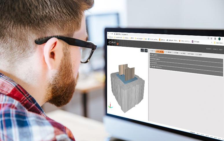
SPIT achors are also available for TEKLA Structure software from TeklaWarehouse.
I-CALC
SPIT RESIN VOLUME CALCULATOR APPLICATION


The I-CALC app allows you to determine the number of SPIT resin cartridges required on your site (rebar or threaded studs), in order to quantify your needs according to working conditions.
CALCULATION SERVICE
i-BIM SOFTWARE
DOWNLOAD THE APP :
i-CALC APPLICATION
SPIT products are specifically designed for trained professional end users.
Operation and safety instructions within the user manuals must be adhered to at all times. Anchors must be selected checked and approved according to technical data, precise calculations and on-site tests if required, particularly in cases where there is undefined base materials or products without technical agreements.
Please feel free to contact us for advice:
www.spitpaslode.com
Pictures cannot be considered as representative. SPIT reserves the right to modify characteristics of their products at any time. Pictures may show accessories not delivered with the standard version.
SPIT SAS
150 route de Lyon 26500
Bourg-lès-Valence FRANCE
Construction Continental Europe
Réf : 052274 -0523
