International Research Journal of Engineering and Technology (IRJET) e-ISSN: 2395-0056
Volume: 12 Issue: 03 | Mar 2025 www.irjet.net p-ISSN: 2395-0072


International Research Journal of Engineering and Technology (IRJET) e-ISSN: 2395-0056
Volume: 12 Issue: 03 | Mar 2025 www.irjet.net p-ISSN: 2395-0072
Swaraj V. Surve1 , N. G. Gore2
1PG Student, Dept. of Civil Engineering, Mahatma Gandhi Mission's College of Engineering and Technology (MGMCET), Kamothe, Navi Mumbai, Maharashtra, India
2Professor, Dept of Civil Engineering, Mahatma Gandhi Mission's College of Engineering and Technology (MGMCET), Kamothe, Navi Mumbai, Maharashtra, India ***
Abstract - This study analyses the seismic performance of RCC buildings (G+10, G+15, and G+25) in Seismic Zones IV and V under medium soil conditions. Using ETABS 2021, buildings were assessed through Equivalent Static, Response Spectrum, and Pushover Analysis. Shear walls with varying reinforcement percentages 0.25% to 1% for ZoneIV and1% to 3% for Zone V were examined to evaluate their impact on structural stability. Key seismic parameters, including base shear, performance points, story drift, displacement, and time period, were compared. Results indicated that taller buildings required higher reinforcement ratios tomeet seismic demands. Zone IV structures performed well with 0.25%–0.75% reinforcement, while Zone V required up to 3% for stability. This study provides insights into optimizing reinforcement strategies for earthquake-resistant RCC buildings
Key Words: Performance-BasedDesign,PushoverAnalysis, Seismic Resilience, Shear Wall Structures, Earthquake Engineering, Seismic Zone IV & V, Steel Reinforcement, ReinforcementOptimization.
Performance-BasedDesign(PBD)isamodernapproach in structural engineering that focuses on predicting how structureswillbehaveunderspecificconditions,particularly during earthquakes. Unlike traditional methods that primarily aim to meet minimum safety standards, PBD establishesclearperformanceobjectives,suchasoperational continuity,immediateoccupancy,lifesafety,andprevention of collapse. This approach enables engineers to design structures that not only prioritize safety but also ensure usabilityafterseismicevents,offeringamorecomprehensive andtailoreddesignsolution.
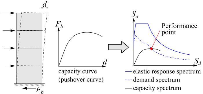
A core component of PBD is Pushover Analysis, a nonlinear static procedure used to evaluate a structure's seismic performance. This method involves incrementally applyinglateralloadstothestructure,simulatingincreasing seismic forces until the structure reaches failure. Through this process, critical weak points are identified, and the overall capacity of the structure to resist seismic loads is assessed.TheinsightsprovidedbyPushoverAnalysisallow engineers to optimize designs, ensuring greater resilience andstructuralreliabilityduringearthquakes.
By integrating PBD with tools like Pushover Analysis, engineers can create buildings that effectively withstand seismic demands, reducing damage and safeguarding occupants.
Performance-Based Design (PBD) is an advanced methodology in structural engineering that prioritizes predicting a building's performance during seismic events rather than merely adhering to traditional design codes. Unlike conventional approaches, which emphasize compliancewithbasicsafetyrequirements,PBDfocuseson achieving specific, measurable performance objectives tailored to the building’s intended use, location, and importance.Thisshiftfromcodecompliancetoperformancedrivendesignprovidesarefinedandadaptableapproachto earthquake-resistant construction, ensuring structures remain functional, resilient, and safe even under extreme seismicconditions.
PBDorganizesperformanceobjectivesintofourdistinct levels,eachreflectingadifferentdegreeofdamagetolerance andusability.Theselevelsserveascleardesigntargetsand offer a flexible framework to address diverse building requirementsbasedontheirrolesandsignificance.
Operational Level (O): Thisisthehighestperformance standard,requiringbuildingstoremainfullyoperationalwith no significant damage afterminor earthquakes. Structures designedtothislevel,suchashospitals,emergencyresponse centres, and data hubs, must ensure uninterrupted functionality of essential services. The design minimizes damagetobothstructuralandnon-structuralcomponents, allowing immediate use without the need for repairs. This levelisparticularlycriticalforinfrastructurethatplaysavital roleinpost-earthquakerecoveryandpublicsafety.
Immediate Occupancy (IO): At the Immediate Occupancylevel,buildingsaredesignedtosustainminimal damageduringmoderateearthquakes,ensuringtheycanbe used immediately after the event. While minor cosmetic damage may occur, the structural integrity and primary functionalityremainintact.Thislevelisessentialforoffices,

International Research Journal of Engineering and Technology (IRJET) e-ISSN: 2395-0056
Volume: 12 Issue: 03 | Mar 2025 www.irjet.net p-ISSN: 2395-0072
residentialcomplexes,andpublicsafetyfacilitieswherequick recovery and continuity of use are priorities. The design ensures the safety of occupants while maintaining the building’s usability, significantly reducing downtime and repaircosts.
Life Safety (LS): The Life Safety level prioritizes protectinghumanlifeduringsevereearthquakes.Buildings designedtothisstandardmaysustainsignificantdamagebut are engineered to prevent collapse, allowing occupants to evacuatesafely.Thislevel iscommonlyappliedtoschools, commercialestablishments,andresidentialbuildingswhere occupant safety is paramount. Although repairs may be extensive, the design ensures the structure can fulfil its primary purpose of safeguarding lives during the seismic event.
Collapse Prevention (CP): Collapse Prevention represents the minimum acceptable performance level, focusingonpreventingtotalstructuralfailureduringmajor earthquakes.Buildingsatthislevelmayexperienceextensive damagebutaredesignedtoremainstandinglongenoughto allow safe evacuation of occupants. This standard is often appliedtoolderstructuresorthosewithbudgetaryorother constraints preventing higher performance levels. While these buildings may be unfit for occupancy after the earthquake,theyaredesignedtomitigatecatastrophicrisks byavoidinglife-threateningcollapses.

Design
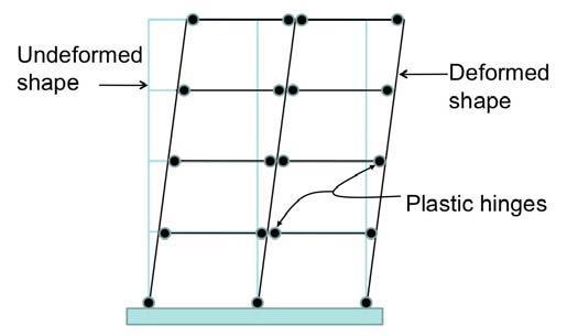
Plastichingesplayacriticalroleinpushoveranalysisby indicating locations of inelastic deformation in structural elements like beams and columns. As lateral forces are applied,thesehingesformatspecificpoints,allowingenergy to be dissipated through plastic deformation. This mechanism is essential for managing seismic loads, as it helpsidentifystructuralweaknessesthatcouldcompromise performanceduringearthquakes.
By analysing the formation and behaviour of plastic hinges, engineers can optimize designs to meet key performance objectives, such as life safety and collapse prevention. Strategically incorporating these insights into thedesignprocessensuresthatbuildingsaremoreresilient to seismic events, minimizing structural damage while safeguardingoccupants.Understandingandaddressingthe anticipatedlocationsofplastichingesenablesengineersto enhance a structure's ability to withstand earthquakes, ensuringbothsafetyandfunctionalityaremaintainedunder extremeconditions.

1. ToanalyseRCCbuildings(G+10,G+15,G+25)using actualplaninETABS2021.
2. ToconductEquivalentStatic,ResponseSpectrum, and Pushover Analysis on each model to assess theirseismicperformance.
3. To evaluate key parameters such as performance points,modalmassparticipation,baseshear,storey drift, and storey displacement for the analysed models.
4. To assess the influence of varying steel reinforcement percentages (0.25%, 0.5%, 0.75%, and1%)forSeismicZoneIVand(1%,1.5%,2.5%, and3%)forSeismicZoneVonseismicparameters andstructuralbehaviour.
5. TocomparetheseismicperformanceofG+10,G+15, and G+25 buildings and evaluate the impact of buildingheightonstabilityanddriftcontrol.
This study aims to analyse and compare the seismic performance of RCC buildings of varying heights (G+10, G+15,andG+25)underseismicloadingconditionsinSeismic Zones IV and V with medium soil. The models were developedusingETABS2021andanalysedwithEquivalent Static,ResponseSpectrum,andPushoverAnalysis.Different shear wall thicknesses and reinforcement percentages (0.25%, 0.5%, 0.75%, and 1% for Zone IV, and 1%, 1.5%,

International Research Journal of Engineering and Technology (IRJET) e-ISSN: 2395-0056
Volume: 12 Issue: 03 | Mar 2025 www.irjet.net p-ISSN: 2395-0072
2.5%, and 3% for Zone V) were applied to assess their influenceonseismicbehaviour,structuralstability,material optimization, and overall earthquake resistance of the buildings.

Storey Details:
G+10 Building:
1. PlanSize:AsPerPlan
2. HeightofBuilding:30m
3. SlabThickness:150mm
4. FloortoFloorHeight:3.0m
5. ShearWallThickness:
i) FromStoreyBaseto5th:300mm
6. BeamSize:230mmx550mm,230mmx650mm, 230mmx750mm(Sizesusedasperstructural framingrequirements)
G+15 Building:
1. PlanSize:AsPerPlan
2. HeightofBuilding:45m
3. SlabThickness:150mm
4. FloortoFloorHeight:3.0m
5. ShearWallThickness:
i) FromStoreyBaseto5th:350mm
ii) FromStorey6thto10th:300mm
iii) FromStorey11thto15th:300mm
6. BeamSize:230mmx550mm,230mmx650mm, 230 mm x 750 mm (Sizes used as per structural framingrequirements)
G+25 Building:
1. PlanSize:AsPerPlan
2. HeightofBuilding:75m
3. SlabThickness:150mm
4. FloortoFloorHeight:3.0m
5. ShearWallThickness:
i) FromStoreyBaseto5th:400mm
ii) FromStorey6thto10th:350mm
iii) FromStorey11thto15th:230mm
iv) FromStorey16thto25th:230mm
6. BeamSize:230mmx550mm,230mmx650mm, 230 mm x 750 mm (Sizes used as per structural framingrequirements)
Loading on Structure:
Live Load:
a) Floor:3kN/m²
b) Terrace:1.5kN/m² Dead Load:
a) 3.75kN/m² Wall Load:
a) Floors:0.23x(3.0–0.55)x10=5.7kN/m
b) Terrace:0.23x1.2x10=2.8kN/m
Seismic Parameters (As Per IS 1893 part-1 2016): SeismicZone(Z):IV&V(AsPerClause6.4.2)
Material Properties:
1. GradeofConcrete:M35
2. GradeofSteel:Fe550
3. DensityofRCC:25kN/m³
4. DensityofSteel:78.5kN/m³
5. DensityofLightWeightBlockWork:10kN/m³
SoilCategory:II[MediumSoil](AsPerClause6.4.2)
Response Reduction Factor (R): 5 [SMRF] (As Per Clause 7.2.6)
ImportanceFactor(I):1.2(AsPerClause7.2.3)
Damping:5%(AsPerClause7.2.4)

International Research Journal of Engineering and Technology (IRJET) e-ISSN: 2395-0056
Volume: 12 Issue: 03 | Mar 2025 www.irjet.net p-ISSN: 2395-0072

4.1 Modal Mass Participation
Table -1: ModalMassParticipationRatiosfor30m Building(G+10)forZoneIV&ZoneV
Table -2: ModalMassParticipationRatiosfor45m Building(G+15)forZoneIV&ZoneV
Mode
Table -3: ModalMassParticipationRatiosfor75m Building(G+25)forZone
&Zone
Table -4: TimePeriodforModelNo.01,ModelNo.02, Model No.03(inseconds)forZoneIV&ZoneV

Volume: 12 Issue: 03 | Mar 2025 www.irjet.net
4.3 Base Shear
Table -5: BaseShear(Vb)CalculationforXandY Direction(inkN)forZoneIV Sr


International Research Journal of Engineering and Technology (IRJET) e-ISSN: 2395-0056
Volume: 12 Issue: 03 | Mar 2025 www.irjet.net p-ISSN: 2395-0072
4.5 Storey Drift
MaximumStoreyDriftinX&YDirection
Chart -4:MaximumStoreyDriftinX&YDirectionfor ZoneIV&ZoneV
Table -7: OptimizationofSteelReinforcementBasedon PushoverAnalysisforZoneIV
Chart -5:StoreyDriftinX&YDirectionforZoneIV
4.6 Pushover-Based Reinforcement Analysis

Chart -6:BaseShearvsMonitoredDisplacementforShear WallLW3with0.75%ReinforcementforModelNo.03for ZoneIV


Chart -7:ComparisonofRequiredandProvidedSteel ReinforcementPercentagesforShearWallsinG+10,G+15, andG+25ModelsforZoneIV
Following are the conclusions obtained from these studies:
1. Seismicdemandsincreasewithbuildingheightand seismicintensity.Tallerbuildings(G+25)inZoneV experiencesignificantlyhigherforces,necessitating greater stiffness, strength, and drift control comparedtothoseinZoneIV.
2. In Zone IV, reinforcement between 0.5%–1% was sufficient for shear walls across different building heights.However,inZoneV,higherreinforcement levelswererequired 2.5%–3%fortallerbuildings (G+15, G+25) and 1%–2.5% for shorter buildings (G+10).
3. In Zone IV, shorter buildings (G+10, G+15) maintained adequate seismic performance even with lower reinforcement percentages (0.25%–0.5%),enablingmaterialefficiency.Incontrast,Zone Vrequiredincreasedreinforcementevenforshorter buildingsduetohigherseismicdemands.

International Research Journal of Engineering and Technology (IRJET) e-ISSN: 2395-0056
Volume: 12 Issue: 03 | Mar 2025 www.irjet.net p-ISSN: 2395-0072
4. Base shear, storey drift, displacement, and hinge formationwereinfluencedbybothbuildingheight andreinforcementlevels,emphasizingtheneedfor tailored design approaches for different seismic zones.
5. Pushoveranalysisprovedvaluableinperformancebased design, identifying optimal reinforcement configurations to balance safety and material efficiency 0.75%–1%fortallerbuildingsinZoneIV and2.5%–3%inZoneV.
6. Modalmassparticipationandtimeperiodanalyses highlighted height-dependent dynamic behaviour. Taller buildings in higher seismic zones require precisereinforcementstrategiestoensurestructural resilience and compliance with seismic safety standards.
Thisresearchareahasvastscopeforthefuturestudies. Somearediscussedbelow:
1. A detailed study on how different soil-structure interaction effects influence the seismic performance of shear walls in varying soil conditions.
2. Conductingamoredetailednon-lineartime-history analysis using real earthquake records to assess structural response under dynamic loading conditions
3. Exploring the use of advanced reinforcement techniques,suchasfibre-reinforcedconcrete,hybrid reinforcement, or high-performance steel, for improvedseismicresilience.
4. Investigating effective retrofitting strategies for existing shear wall structures to enhance seismic resistancewithoutsignificantmaterialandfinancial costs.
5. Performing a comparative cost-benefit and environmental impact analysis of optimized reinforcement strategies versus conventional methodstoenhancesustainabilityandefficiency.
[1] P.May et al.,“ComparativestudyofPerformanceof RCC Multi-Storey Building for Koyna and Bhuj Earthquakes,” vol. 7, no. 5, pp. 45–52, 2017, doi: 10.9790/9622-0705024552.
[2] C.EngineeringandC.Engineering,“PERFORMANCE BASEDEVALUATIONOFFLATSLAB,”no.2006,pp. 282–289,2016.
[3] S.A.Arasy,“TheEffectivenessofPerformanceBased Design to Establish Architectural Feature of
StructuralDesignforSlenderBuilding,”vol.4,no.1, pp.81–87,2016,doi:10.5176/2251-3701.
[4] B. Storey, “PERFORMANCE BASED SEISMIC ANALYSISOFRCBUILDINGNoofStories,”pp.278–282,2015.
[5] C.Engineering,“PERFORMANCEBASEDPUSHOVER ANALYSISOFR.C.CFRAMESFORPLAN,”vol.2,no. 7,pp.1544–1552,2014.
[6] P.B. Oni and S.B. Vanakudre,“PerformanceBased Evaluation of Shear Walled RCC Building by PushoverAnalysis,”vol.3,pp.2522–2525,2013.
[7] M.D.ShahandA.N.Desai,“PERFORMANCEBASED ANALYSISOF,”no.May,2011.
[8] O. O. El-mahdy, G. A. Hamdy, and A. S. Yassin, “PerformanceBasedSeismicDesignofTwoRCHighRiseBuildings,”no.April,pp.101–113,2023.
[9] P.AnandandP.Kumar,“SeismicDesignonaG+10 Rcc Residential Structure based on Performance,” vol.32,no.3,2022,doi:10.22068/ijaup.699.
[10] M. Dinesh, “EARTHQUAKE PERFORMANCE OF G + FOUREXISTINGR.C.CBUILDINGBYUSINGE-TABS SOFTWARE,”vol.4,no.June,pp.19–24,2021.
[11] D. Naxine and A. Nag, “Strength and durability of concretebypartialreplacementofsandby Copper SlagandcementbyEggShellPowder:AReview,” IOP Conf. Ser. Earth Environ. Sci.,vol.1084,no.1,2022, doi:10.1088/1755-1315/1084/1/012019.
[12] S. Al-safi, “Evaluation of performance-based earthquakeengineeringinYemen,”vol.6,no.1,pp. 10–22,2020.
[13] D.R.NaxineandS.Ghodmare,“Experimentalstudy of Compressive Strength of Concrete by Partial ReplacementofCementwithEggShellPowderand Fine Aggregate with Copper Slag,” IOP Conf. Ser. Earth Environ. Sci., vol. 1326, no. 1, pp. 1–8, 2024, doi:10.1088/1755-1315/1326/1/012077.