
International Research Journal of Engineering and Technology (IRJET) e-ISSN:2395-0056
Volume: 12 Issue: 04 | Apr 2025 www.irjet.net p-ISSN:2395-0072


International Research Journal of Engineering and Technology (IRJET) e-ISSN:2395-0056
Volume: 12 Issue: 04 | Apr 2025 www.irjet.net p-ISSN:2395-0072
A. M. Halmare1, Tejas Meshram2, Nikita Narnaware3, Manish Patle4
1Assistant Professor, Department of Electrical Engineering, KDK College of Engineering, Nagpur, Maharashtra, India 234UG Students, Electrical Engineering, KDK College of Engineering, Nagpur, Maharashtra, India
Abstract - Three-phase induction motors are widely used in industrial applications due to their robustness, efficiency, and reliability. The primary aim of this paper is to monitor and protect the three-phase induction motor (IM) in case of faults like overheating, overcurrent, overvoltage, and single phasing. Protecting three-phase induction motors from these problems is essential since they can lower their efficiency. In the protection scheme, the current transformer (CT) and the Potential transformer (PT) are used to monitor the current and voltage of the induction motor on the LCD, respectively. The brain of the protection scheme Arduino Nano continuously checks the various parameters of an induction motor. The Arduino Nano has some pre-set values, and with the help of these pre-set values, Arduino Nano compares them with the parameter value. The relay receives the Arduino signal when a pre-set value exceeds, and the relay will trip the three-phase contactor and disconnect the three-phase supply of the induction motor.
Key Words: induction motor, overvoltage, protection, overcurrent, single phasing.
Manymotorsareutilizedforvarioustasksaroundus,fromhouseholdappliancestomachinetoolsincommercialbuildings.In many sectors nowadays, electric motors are a vital source of power. These motors must have a wide range of functions and performances. Since IM motors are the most commonly used for automation, industrial control, and appliances, they are robust, dependable, and long-lasting. Three-phase induction motors typically experience overvoltage, overcurrent, overheatingandsingle-phasingproblems.
Thethree-phaseinductionmotorsbegintooverheatwhenthesuppliedvoltageishigherthanthemotor'srating.Itisidealfor a three-phaseinductionmotortooperatewithoutthese kindsofissues. Variationsintheinductionmotorsettingscausethis issue to arise. It is essential to protect the three-phase induction motor from these potential problems while it operates continuously.
Three-phaseinductionmotor’slonglifespanismostlydependentonitsprotection.Researcheshavecreatedlimitedandcostly protection for things like damaged rotor bars, thermal protection and stator winding protection. The induction motor primarilyrequiresprotectionagainstinputsupplyfluctuations.Ifsupplyvoltage,current,andtemperatureareincreased,then theArduinoNanosendsasignaltotherelaythat,inturn,actuatesathree-phasecontactortosafelydisconnectthemotorfrom itspowersource.
A. Ivana Z. Giceva [1]
IvanaZ.Gicevastatedthatthree-phaseIMdoesnotstartifoneofitsphasesisdisconnected,leavingthemotortooperatein a physically two-phase regime. In certain situations, the motor would have trouble starting and we could hear buzzing. Maintaining such a routine has no practical or physical significance because the motor cannot start and may occasionally cause minor motor damage. When a motor is loaded with a rated or lower-than-rated load, it loses one of its phases for a varietyofcauses,suchasablownfuse,adamagedpowersupplyline,apoorterminalconnection,etc.,leavingthemotorto runontheremainingtwophases.Thisisaverydifferentregime.Ifprotectivemeasuresarenotimmediatelyimplemented, this so-called single phasing operation mode may result in a number of operational issues for IM, including the rapid deteriorationofmotorparametersanditsburnout.

International Research Journal of Engineering and Technology (IRJET) e-ISSN:2395-0056
Volume: 12 Issue: 04 | Apr 2025 www.irjet.net p-ISSN:2395-0072
Pragasen Pillayet.dal.Examines the three-phaseinductionmotorundertheimpact ofundervoltageand overvoltage. Ina complicated industrial system, the voltage at the motor terminals may be greater than the nominal value, and in a fully loadedindustrialsystem,itmaybesignificantlylower.NEMAandIEEEhavevaryingdefinitionsofvoltageunbalance.
C. Abalagan and Sudha M. [3]
AbalaganandSudhaM.suggestedamethodtopreventsinglephasinginthree-phaseinductionmotors.Thismethodusesa PIC16F877microcontrollertosamplethevaluesofeachphase,whichatransformerthenconvertstolowvoltageac.AnADC converter is used to transform the signals into digital values. When a malfunction arises, the controller opens the usually closedcontactoranddisconnectsitfromthepowersourceaftercontinuallycomparingthedigitalvaluewiththereference value.A2kWmotorisprotectedagainstsinglephasing,undervoltage,andovervoltage,andthemotorisdisconnectedinthe eventthatanyoftheseconditionsarise.
3.1
TheblockdiagramoftheproposedmotorprotectionsystemisshowninFig.1.Thesystemincludesastep-downtransformer, currenttransformer,relay,andcontactorunitalongwiththeArduinoNano.RectifiercircuitsareusedtoconvertACvalues of theCTandPTintoDC.Theinformationcollectedfromthepotentialtransformerandcurrenttransformerafterconvertinginto DCvaluesisthendigitallytransmittedtotheArduinoNanoafterpassingthroughthecurrentandvoltagemeasuringcircuits.
The Arduino Nano features a built-in analog to digital (ADC) converter, eliminating the need for an external ADC unit. Typically, the Arduino Nano A/D converter (ADC) can process input signals below 5V. Therefore, sensors must be chosen in accordance with the specifications of the Arduino Nano design. Necessary comparisons are performed within the Arduino Nanobasedonthepredefinedlimitvaluesthathavebeeninputorprogrammed.Ifanabnormalconditionarises,theArduino Nanostopsthemotorbysendingacontrolsignal.Keymotorparameterssuchasfullloadcurrentinamperesandratedvoltage involtsmustbeenteredintotheprogrammingunittoautomaticallydeterminetheappropriatemotorprotectioncurve.This systemprovidesseveralprotectivefunctions.
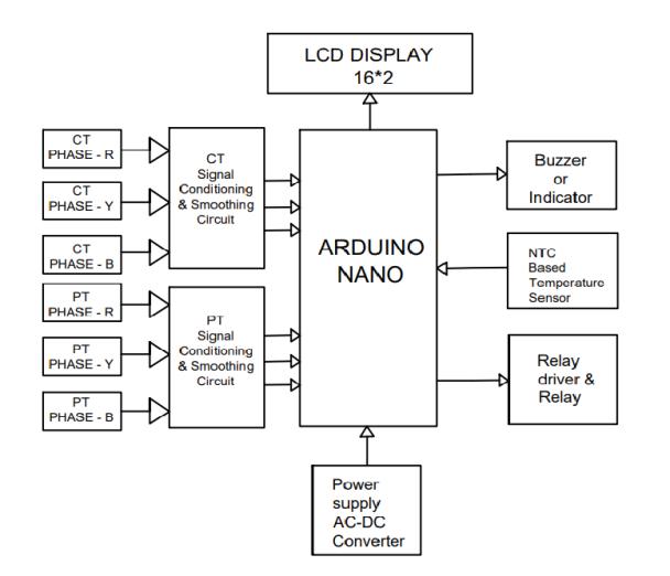
Fig.1.Blockdiagramofthreephaseinductionmotorprotectionunit
Thesystemoffersprotectionagainstsingle-phasing,over-voltage,overcurrent,andoverheatingconditions.Thecontrolofthe systemismanagedbytheArduinoNano.Thissystemoperateswithanymotordesignandmaintainsahighdegreeofaccuracy.

International Research Journal of Engineering and Technology (IRJET) e-ISSN:2395-0056
Volume: 12 Issue: 04 | Apr 2025 www.irjet.net p-ISSN:2395-0072
The method is highly sensitive, quick, and capable of detecting faults during operation and prior to start up. Once the thresholdsformaximumpermissibleovervoltagearesurpassed,theArduinoNanoproducesatripsignalthatshutsdownthe induction motor, thereby protecting the induction motor from severe over voltage situations. Similarly, other faults are monitored,ensuringtheinductionmotorisprotectedagainstthoseissues.
4.1 Current Transformer
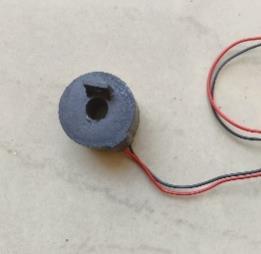
Atoroidal currenttransformer(CT)isa keycomponentin electrical protectionsystems.Unlikeconventional transformers,a toroidalCTdoesnothaveaprimarywinding.Instead,theconductorcarryingthecurrenttobemeasuredpassesthroughthe center of the toroidal core, which is ring-shaped. The working principle is based on Faraday’s Law of Electromagnetic Induction, where the alternating current flowing through the conductor induces a proportional current in the secondary winding wrapped around the core. These transformers are known for their high accuracy and reliability, making them ideal for precise current measurements in protection circuits, industrial automation, and other applications requiring careful monitoringofelectricalparameters.
Apotential transformer (PT)isanother form of instrument transformer designedto reduce highvoltagestolower, safe, and measurable levels for monitoring and protection systems. Operating on the principle of electromagnetic induction, PTs provide accurate voltage measurements while minimizing errors. These transformers are integral to electrical systems that requireprecisevoltageregulationformonitoring,protection,andcontrolpurposes.Potentialtransformersaretypicallyused in high-voltage environments, where they ensure that voltage levels are brought down to manageable levels for both safety andmeasurementaccuracy.

An NTC (Negative Temperature Coefficient) thermistor is a type of resistor whose resistance decreases as the temperature increases.Thesethermistorsarewidelyusedintemperature-sensingapplications,suchasinmotorprotectionsystems,where even slight variations in temperature can be critical. NTC thermistors are small, energy-efficient, and capable of detecting rapid changes in temperature. With a wide operational range, often from -50°C to over 300°C, they are used in applications thatdemandprecisetemperaturecontrolandmonitoring,ensuringthesafetyandproperoperationofequipmentlikemotors andotherelectronicsystems.

International Research Journal of Engineering and Technology (IRJET) e-ISSN:2395-0056
Volume: 12 Issue: 04 | Apr 2025 www.irjet.net p-ISSN:2395-0072

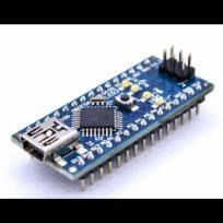
The Arduino Nano is a compact, versatile microcontroller based on the ATmega328P or ATmega168, designed for projects requiringsmallformfactorandhighperformance.Itispoweredviaamini-BUSBconnection,withanoperatingvoltageof5V, butitcanacceptinputvoltagesrangingfrom5Vto20V.TheArduinoNanooffers8analoginputpinsandaclockspeedof16 MHz, making it suitable for a wide variety of applications, from simple sensors to complex control systems. Due to its small sizeandeaseofuse,theArduinoNanoispopularinembeddedsystems,robotics,andDIYelectronics.
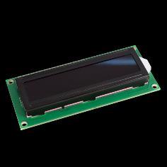
A16x2LCDdisplayisacommonlyuseddisplaymoduleinelectronicprojects,capableofshowing16charactersacross2rows. With a standard operating voltage of 5V, these displays are essential for interfacing with microcontrollers like the Arduino, providing visual output for data, status information, and menus. The contrast of the display is adjustable using a potentiometer, typically 10K ohms, connected to the V0 pin. This feature allows for better readability in different lighting conditions,makingthe16x2LCDapopularchoiceinindustrialautomationandhomeappliances.
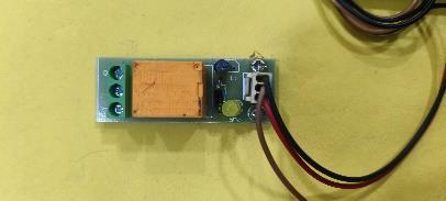
A relay module is an electrically operated switch used to control high-voltage devices, such as motors, fans, and household appliances, from low-voltage control systems. The module operates at a 5V DC input, and it uses an electromechanical relay thatcanswitch bothACand DCloads.Withtheability tohandlehighswitchingvoltages(upto 250V AC),relaymodulesare ideal for interfacing microcontrollers with high-power electrical circuits, providing an essential interface in automation and controlsystems.

International Research Journal of Engineering and Technology (IRJET) e-ISSN:2395-0056
Volume: 12 Issue: 04 | Apr 2025 www.irjet.net p-ISSN:2395-0072
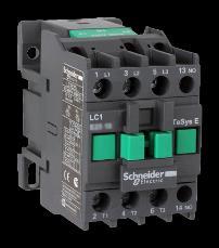
A contactor is an electromechanical switch primarily used for controlling high-power electrical loads, particularly in threephasemotorcircuits.Itoperatesbyusingamagneticcoiltoopenorcloseelectricalcontacts,allowingorinterruptingtheflow of electricity to the connected load. Three-phase contactors are commonly used in industrial environments and commercial settings to switch motors and other high-power devices. These contactors are designed to handle the demands of large electricalsystems,providingbothprotectionandoperationalcontrolofmachineryandotherelectricalequipment
5.
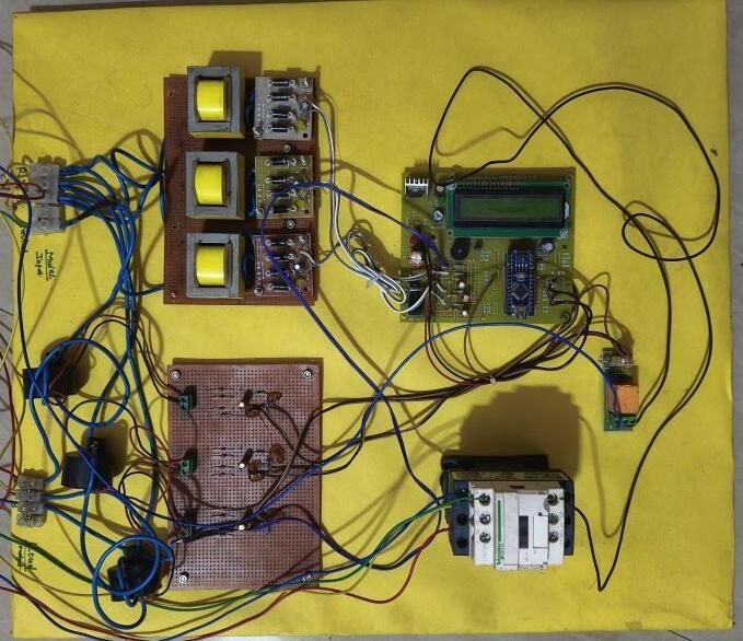
Hardwaresystem:
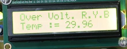
ResultonLCD:
OverVoltage: If the supply voltage of the motor is more than 250V, then an over-voltage fault is detected and the motor stops running.

International Research Journal of Engineering and Technology (IRJET) e-ISSN:2395-0056
Volume: 12 Issue: 04 | Apr 2025 www.irjet.net p-ISSN:2395-0072
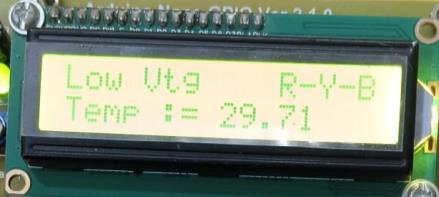
Undervoltage:
Ifthesupplyvoltageofthemotorislessthan190V,thenundervoltagefaultisdetectedandthemotorstopsrunning.
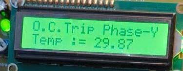
OverCurrent:
If the supply current of motor is more than 2.5Ampere, then an over-current fault is detected and the motor stops running.
SinglePhasing:
Ifoneofthephasesofthesupplyofmotorisdisconnectedfromthemotor,thenasinglephasingfaultis detectedand themotorstopsrunning.

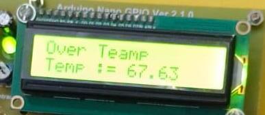
Overtemperature:
Ifthetemperatureofthemotorisincreasedthan65degreesCelsius,thentheovertemperaturefaultisdetectedand themotorstopsrunning

International Research Journal of Engineering and Technology (IRJET) e-ISSN:2395-0056
Volume: 12 Issue: 04 | Apr 2025 www.irjet.net p-ISSN:2395-0072
The implementation of this protection system for three-phase induction motors demonstrates an effective and affordable approach to mitigating the risks associated with electrical faults such as single phasing, overcurrent, overvoltage, and overheating.ByintegratingtheuseofCTs,PTs,andArduinoNanowithrelaymodulesandcontactors,thesystemensuresrealtime protection and enhances the reliability of motor operations. Furthermore, its low-cost design makes it accessible to a widerangeofapplications,improvingmotorsafetywithoutsignificantinvestmentinexpensiveindustrialprotectiondevices. The system can be further expanded or customized to address other motor protection needs, offering a scalablesolution for variouselectricalcontrolsystems.
Wewouldliketoexpressourdeepestgratitudetoallthosewhohavecontributedtothesuccessfulcompletionofthisproject First and foremost, we are profoundly thankful to our respected guide, Prof. A. M. Halmare, for his exceptional guidance, continuous support, and inspiration throughout the entire project. His expertise and thoughtful advice have been pivotal in helpingusnavigatethechallengesweencounteredalongtheway.Wewouldalsoliketoextendoursincereappreciationtothe faculty members who provided valuable insights and feedback, which significantly enhanced the quality of our work. Their contributionshaveplayedakeyroleinthedevelopmentandrefinementofthisproject.Withouttheguidance,resources,and moral support from all these individuals, the successful completion of this project would not have been possible. We truly appreciateeachone’sroleinmakingthisendeavourasuccess.
[1] Ivana Z. Giceva, “Single Phasing of Three Phase Induction Motors under Various Load Conditions”,2018 23rd International Scientific-Professional conference on Information Technology (IT).
[2] PillayP.,HofmannP.AndManyage.“Deratingofinductionmotorsoperatingwiththecombinationofunbalancedvoltages andoverorundervoltages,” IEEE Transactions on Energy Conversion,Vol.17,no.4,pp.485=491,Dec.2002.
[3] SudhaM.andAnbalganP.,“ANovelProtectingMethodforInduction MotorAgainstFaulttoVoltageUnbalanceandSingle Phasing,” 33rdAnnual Conference of the IEEE Industrial Electronics Society,2007,pp.1144-1148,5-8Nov.2007,Taipei.
[4] Nagesh Bhakare, Laxman Ghanvat, “Detection of fault of three phase induction motor using Arduino uno R2 Microcontroller”InternationalJournalofTrendinResearchandDevelopment,Volume3(5),ISSN:2394-9333
[5] R. Bayindir , "Fault Detection And Protection Of Induction Motor Using Sensors " Dept. of Electrical Educ., Gazi Univ.,AnkaraIEEETransactionsonEnergyconversion(Volume:23,Issue:3),ISSN:0885-8969.
[6] D. Kumar, A. Basit, A. Saleem and E. G. Abbas, "PLC Based Monitoring & Protection of 3-Phase Induction Motors against Various Abnormal Conditions", 2019 2nd International Conference on Computing Mathematics and Engineering Technologies (iCoMET),pp.1-6,2019.
[7] Rupali Shivpuje,“Microcontroller based fault detection and protection system for induction motor”,2017 International Conference on Intelligent computing and control systems(ICICCS) , Madurai,India,15-16June2017.
[8] Ganapathy Subramanian,“Fault Detection and Protection of Induction Motors Using Sensors”, IEEE IFET College Of Engineering Villupuram III-BE Department.