International Research Journal of Engineering and Technology (IRJET) e-ISSN: 2395-0056

Volume: 09 Issue: 09 | Sep 2022 www.irjet.net p-ISSN: 2395-0072

International Research Journal of Engineering and Technology (IRJET) e-ISSN: 2395-0056
Volume: 09 Issue: 09 | Sep 2022 www.irjet.net p-ISSN: 2395-0072
1,2,3
4
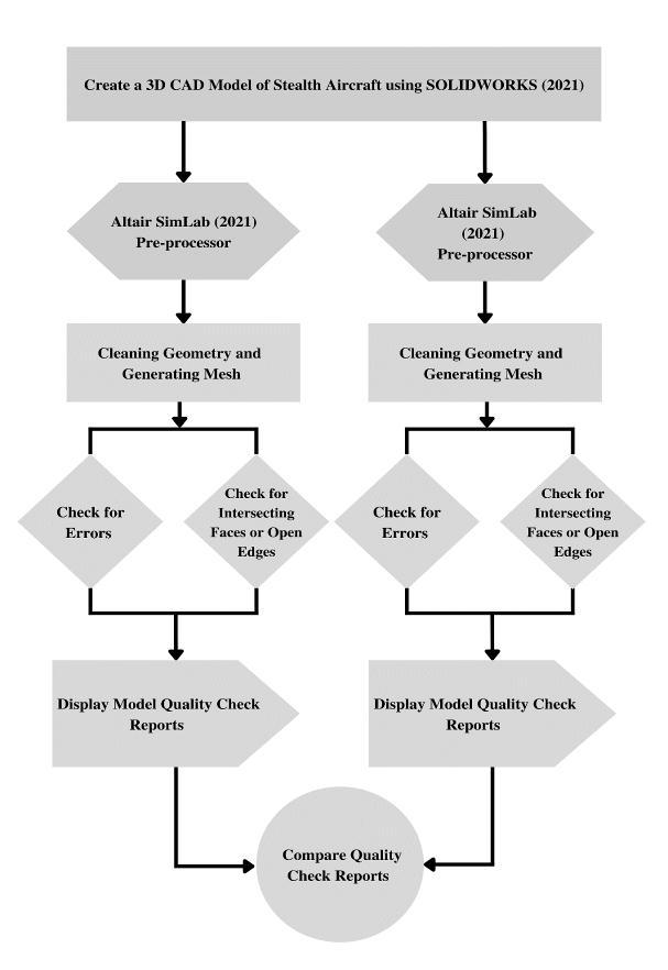
Abstract - This research focuses on creating a 3D CAD model of a stealth aircraft, cleaning the CAD geometry, and generating the mesh using the pre-processing software Altair SimLab (2021) and HyperWorks (2019.1). Valid CAD geometry must be checked for errors, intersecting faces, and open edges before meshing and after meshing compared to the quality check reports from SimLab and Hypermesh for Aspect Ratio Check, Jacobian Ratio Check, Warpage Angle Check, Skewness, Quad Interior Angle Check, and Tria Interior Angle Check. The quality of the mesh plays a key role in the design analysis accuracy. As a result, we optimized the design to the point where elements passed with 99.5% accuracy in the model quality check report for Simlab and Hypermesh.
Key Words:StealthAircraft,Meshing,SimLab,HyperWorks, CADgeometry
In the early stages of design analysis, where approximate resultsmaysuffice,youcanspecifyalargerelementsizefor afastersolution,butforamoreaccuratesolution,asmaller element size may be required. There has been a lot of research activity on the subject of computational fluid dynamicsforaerodynamicapplicationsinrecentyears.In theory, advancements in the numerical solution of the Potential and Euler equations allow for inviscid flow simulation around complex aerodynamic forms. At this stage, substantial emphasis was placed on methods for producing meshes on which such calculations could be conducted.
***
Meshingistheprocessoftransformingirregularshapesinto more recognizable volumes called "elements". Meshing is one of the most crucial steps in performing an accurate simulation. A mesh is made up of elements that contain nodes or coordinate locations in space that can vary depending on the element type and which describe the
International Research Journal of Engineering and Technology (IRJET) e-ISSN: 2395-0056
Volume: 09 Issue: 09 | Sep 2022 www.irjet.net p-ISSN: 2395-0072
geometry'sshape.Thesizeofthegeneratedmesh(number of nodes and elements) depends on the geometry and dimensionsofthemodel,elementsize,meshtolerance,mesh control, and contract specifications. The amount of time available to commit to the mesh, and the amount of time availabletoinvestinsolvingitallaffectthemesh'squality.
Anaspectratioistheratioofwidthtoheightorlength.Itis theelementaldeviationfromhavingallsidesofequallength. The best numerical accuracy comes from a mesh with uniform,perfectelementsandedgesthatareallofthesame length. It is quite challenging to generate a mesh of ideal components for general geometry. Some of the generated elementsmayhaveedgesthataresignificantlylongerthan others due to narrow edges, curved geometries, thin features,andsharpcorners.Resultsarelessprecisewhenan element'sedgeshavelargelengthdiscrepancies.
The Jacobian ratio calculates how far an element deviates frombeingperfectlyshaped.Tomapacurvedgeometry,the Jacobian ratio of an element rises as the curvature of its edgesincreases.
Proximity to an idealistic face or cell (i.e., equilaterally or equiangularity)
Thewarpingangle,whichistheanglebetweenthenormalof two(triangular)planescreatedbydividingthequadelement alongdiagonals,isusedtomeasurehowfaraquadelement deviatesfrombeinginasingleplane.
Meshes with a well-known pattern in which the cells are arranged are known as structured meshes. The cells are organized in a particular order, which results in a regular topologyforsuchamesh.Suchmeshesmakeiteasytolocate neighboring cells and points due to their design and structure. Rectangular, elliptical, and spherical coordinate systemsarecombinedtoformstructuredmeshes,whichare thenutilized toproducea regulargrid.InCFD,structured meshesarefrequentlyemployed
As the names suggest, unstructured meshes are more general and can randomly form any geometry shape. Unstructured meshes do not follow a consistent pattern
International Research Journal of Engineering and Technology (IRJET) e-ISSN: 2395-0056
Volume: 09 Issue: 09 | Sep 2022 www.irjet.net p-ISSN: 2395-0072
because,unlikestructuredmeshes,theconnectivitypattern is not fixed. Unstructured meshes, however, offer greater flexibility. Unstructured meshes are generally used in complexmechanicalengineeringprojects.
Unstructured mesh generation schemes have advanced almostindependentlyofworkonstructuredmeshesThisis primarilyduetothefactthatfiniteelementmethodshave historically used unstructured meshes, but the nature of finitedifferencemethodslendsthemselvestoastructured regularmesh.Onlyrecentlyhaveengineersinthesedomains beguntoworkmorecloselytogetherasaresultofincreased understandingofthemeshcreationissuesthatareprevalent inbothofthesefields.
Theunstructuredapproachoffersanaturalenvironmentfor meshandisadaptiveforverycomplexgeometricaldesigns. Somedownsidesincludenotbeingsuitableforallclassesof flow algorithms and multigrid implementation, as well as beingratherwastefulincomputermemory.Itisimportantto keep in mind that the disadvantages of one strategy are actuallyitsunderlyingbenefits.
The primary distinction between unstructured and structured meshes is the type of data structure that best describesthemeshes.Astructuredmeshofquadrilateralsor trianglesismadeupofasetofcoordinatesandconnectivity thatreadilymapintomatrixelements.Thenearbyelements inthemeshpointmatrixaretheneighboringpointsinthe meshinphysicalspace.However,foranunstructuredmesh, thepointscannotberepresentedinthiswayandmust be supplementedwithadditionalinformation.Thelinkbetween anytwopointsmustbeexplicitlydefinedintheconnectivity matrixforeachpoint.
Theadvantagesofthestructuredmethodincludeflexibility in the creation of various flow algorithms, effective use of computervectorarchitecture,reductionofsolvertimeand computermemoryrequirements,andafavorablesettingfor multigrid-based algorithm convergence. The relative drawbacks are the infrequent possibility of mesh point enrichment and the absence of complete freedom for exceedinglycomplicatedgeometricalregions.
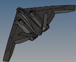
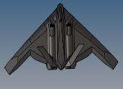
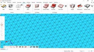
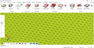
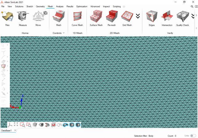
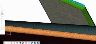
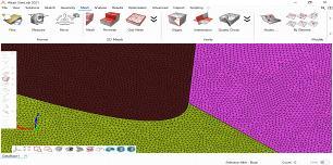
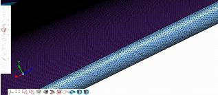
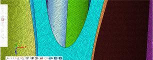
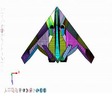
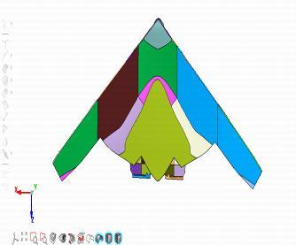
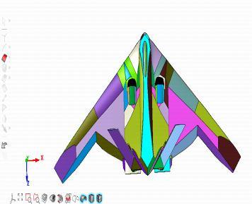
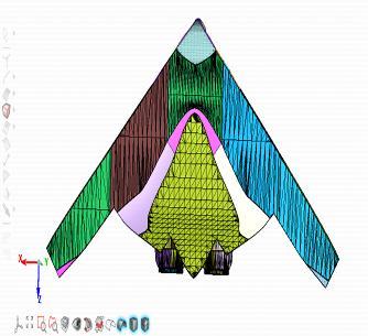
Theedgesofanelementmaycrossoveroneanotherinthe vicinity of very sharp or curved borders, distorting the elementandgeneratingself-intersectinggeometry.Witha negativeJacobianratio,distortedelementsgiveinaccurate results.Butinourmodelfromfigures(a),(b),(c)thereare no edges crossing over, element distortion, and selfintersectinggeometry.
International Research Journal of Engineering and Technology (IRJET) e-ISSN: 2395-0056
Volume: 09 Issue: 09 | Sep 2022 www.irjet.net p-ISSN: 2395-0072
Utilizing the three given nodal points, TRI3 enables the software to produce a linear plane to interpolate deformation from. Because a linear plane of deformation producesaconstantstrainand,asaresult,stressesanentire element, there is a problem with the correctness of the solution. But in reality, stress is always changing and structured,thusitisquitemisleadingtosaythatsomething is under permanent pressure. Because of this, outcomes produced by TRI3 elements frequently have an excessive amountofstiffnessandundervaluestress.Asecond-orderor
quadraticvariationofTRI3isTRI6.Beingasecond-orderhas onesignificantbenefit.Nolongerissoftwarerestrictedtoa linearplaneofdeformation.Thesoftwaremayapplyalinear plot of stress and strain by using a polynomial plot for deformation,increasingaccuracyoverTRI3.Iftheanalysisis straightforward enough and sufficient TRI3 elements are used,thesoftwarecanproducefindingsrelativelyquickly. However, TRI6 will demand significantly more computationalresourcesandtimeduetothefactthatthere aretwiceasmanynodes.
International Research Journal of Engineering and Technology (IRJET) e-ISSN: 2395-0056
Volume: 09 Issue: 09 | Sep 2022 www.irjet.net p-ISSN: 2395-0072
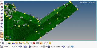
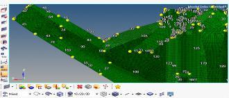
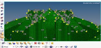
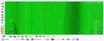
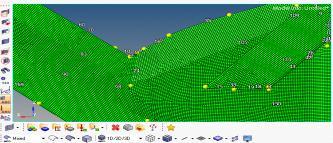
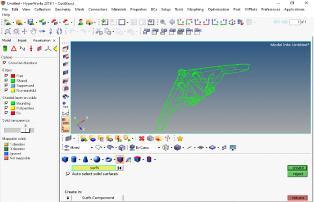
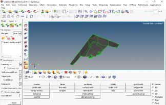
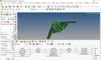
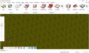
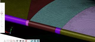
ValidCADgeometrymustbecheckedforerrors,intersecting faces, and open edges. Set the view to mix to check for geometry errors, and then confirm there are no free or nonmanifoldedgesinthevisualizationpanel(theredcolour indicates free edges, while the yellow colour indicates nonmanifold edges). external flow CFD simulation, it is essentialthatthemeshcompletelyenclosesthevolume,i.e., therearenofreeedgesingeometry.
(p) (q) (r) (s) (t)
International Research Journal of Engineering and Technology (IRJET) e-ISSN: 2395-0056
Volume: 09 Issue: 09 | Sep 2022 www.irjet.net p-ISSN: 2395-0072
International Research Journal of Engineering and Technology (IRJET) e-ISSN: 2395-0056
Volume: 09 Issue: 09 | Sep 2022 www.irjet.net p-ISSN: 2395-0072
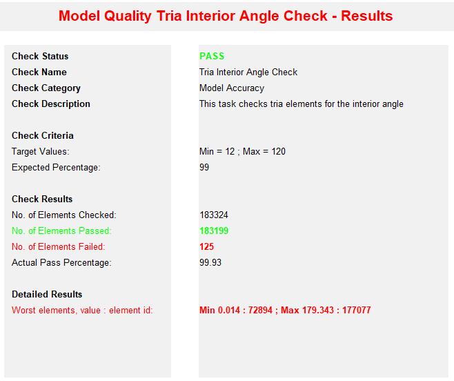
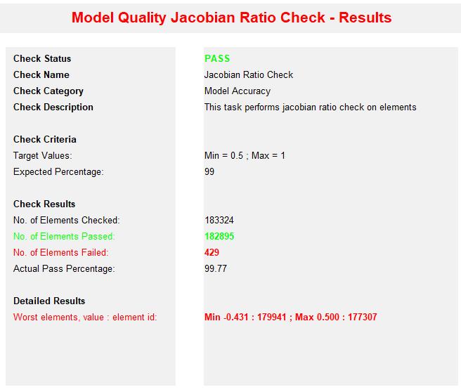
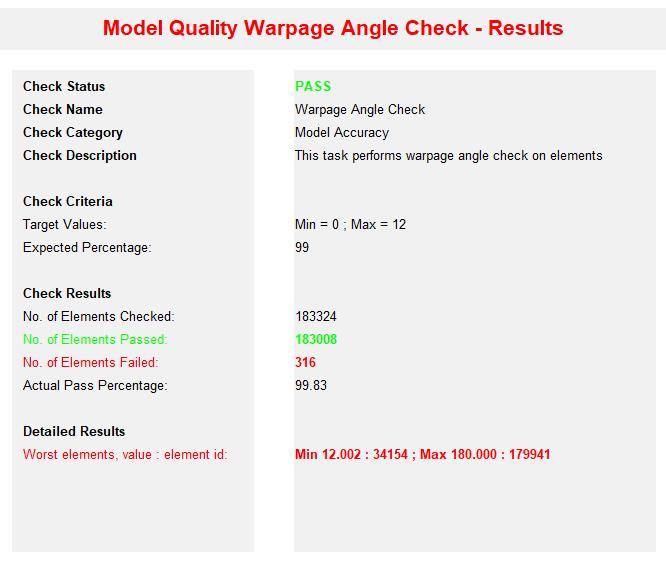
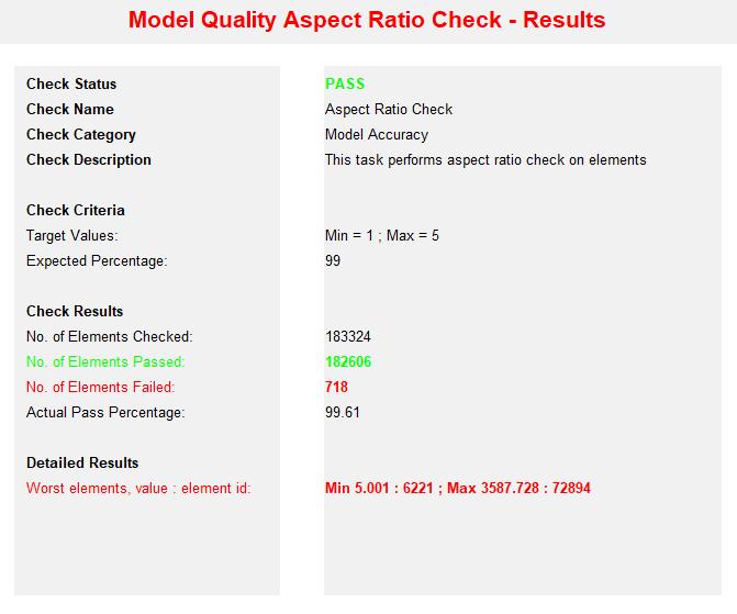
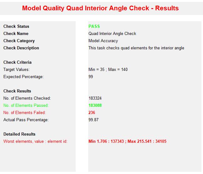
Innumericalsimulations,theresultsareasgoodasthemesh quality.Thisiswhyitisimportanttoensurethatthemesh qualityisimprovedtoproducemoreaccurateresults.From model quality check results in Hypermesh, 1,83,324 total elementswerechecked.Thereare718failedelementsand 1,82,606passedelementswith99.61%accuracyfromaspect ratio checks; 316 failed elements and 1,83,008 passed elementswith99.83%accuracyfromWarpageanglechecks; 236 failed elements and 1,83,088 passed elements with 99.87% accuracy from Jacobian ratio checks;125 failed elements and 1,83,199 passed elements with 99.93% accuracyfromTriainterioranglechecks.
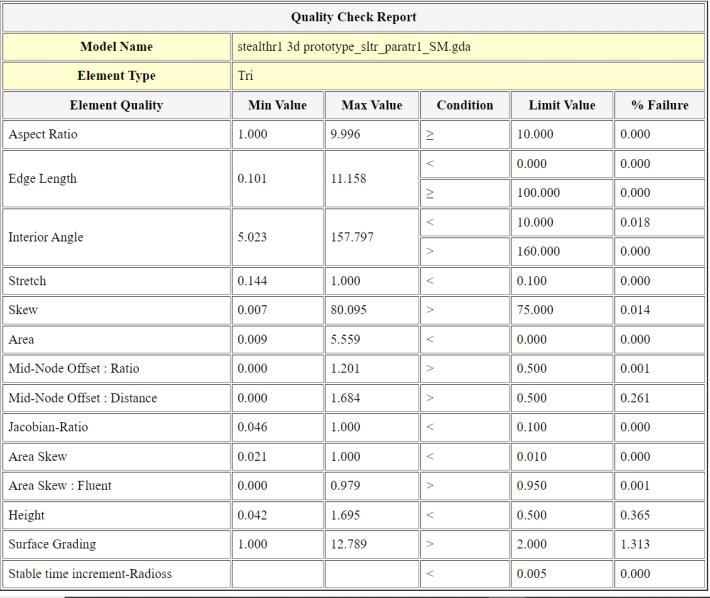
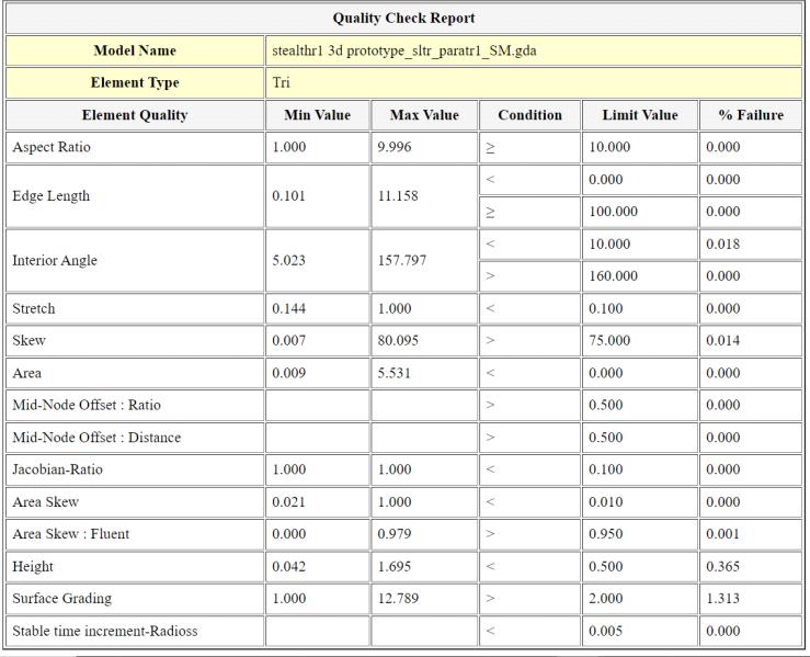
FortheSimLabqualitycheck,thereis0%failureinaspect ratio, edge length, stretch, Jacobian ratio, and area skew. Interioranglefailure was0.18%,skewfailurewas0.14%, mid node offset: the ratio was 0.01%, mid node offset: distance was 0.261%, height was 0.365%, and surface gradingwas1.313%.
[1] NPWEATHERILL,Meshgenerationforaerospace applications, Sadhana, Wol. 16, Part 1, June 1991, pp.1-45.
[2] ASR engineering design and Analysis, https://asrengineering.com/
[3] Prescient Technologies, https://www.prescient.com/knowledge-center/productdevelopment-by-reverse-engineering/mesh.html
[4] Ansys, https://www.ansys.com/enin/blog/fundamentals-of-fea-meshing-forstructural-analysis
[5] HemantAmrutPagar,AnilS.Maheshwari,RaviK.S. Garigipati, Dhanashree Amrut Pagar, Stealth Counter-Stealth Technology, and Techniques for Enhancing Stealth and Counter-Stealth, IJRTI, Volume7,Issue7,PageNo1238-1244ISSN:24563315,July2022.
2022, IRJET | Impact Factor value: 7.529 | ISO 9001:2008 Certified