International Research Journal of Engineering and Technology (IRJET) e ISSN: 2395 0056

Volume: 09 Issue: 08 | Aug 2022 www.irjet.net p ISSN: 2395 0072
International Research Journal of Engineering and Technology (IRJET) e ISSN: 2395 0056
Volume: 09 Issue: 08 | Aug 2022 www.irjet.net p ISSN: 2395 0072
T. Jaya Sriram1 , P. Jayanth Reddy2 , P. Gangadhar Raju3, R. Kanakaraju4
1 Assistant Professor, Department of Mechanical Engineering, Guru Nanak Institute of Technology, Ibrahimpatnam, R.R. Dist 501506, India 2,3,4 UG Student, Department of Mechanical Engineering, Guru Nanak Institute of Technology, Ibrahimpatnam, R.R. Dist 501506, India ***
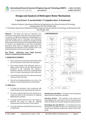
Abstract – The design and study of a helicopter rotor mechanism is the project's majorgoal. The present problemis to properly and effectively apply these methodologies to a complicated design, such as a helicopter rotor mechanism, where the aerodynamics are complex and changing and the designspace has manydimensions.Thedesignphaseisequally as crucial as the optimization process since optimization approaches often require a beginning design point. The computational fluid dynamics (CDF) methods used in the initial optimization of rotors were made simpler.
Key Words: Solidworks, Ansys, Rigid Dynamics analysis, Computational fluid dynamics
Duetousingmorecomponents,heavyRotorstake moreofthepowertobeusedtoliftahelicopter
The forward speed of the helicopter leads to a higher relativeairflow over theadvancingsideas compared to the retreating side causing a hazardous situation termed the retreating blade stall.Asaresult,adissymmetryofliftisobserved.
Itisimmenselyimportanttohavethesameamount ofliftacrosstherotordisk.
Take off and landing problems occur due to the dragforceandstreamliningoftheairfoilblades
1. To design the helicopter rotor mechanism with simplecomponentsbyusingSolidworkssoftware
2. Tocreateanoptimalsolutioninthemechanismso reduce the effect on the mechanism by Applying RigidDynamicsAnalysis
3. To design aerofoil shapes for the rotor blades to decrease the stress on them by Applying ComputationalFluidDynamics(CFD)Analysis
4. TotestthedesignbyusingFEMsoftwarelikeAnsys orSolidworks
Identification of Problem: Toimprovearotormechanism whiletheliftofinhelicoptertakeplace
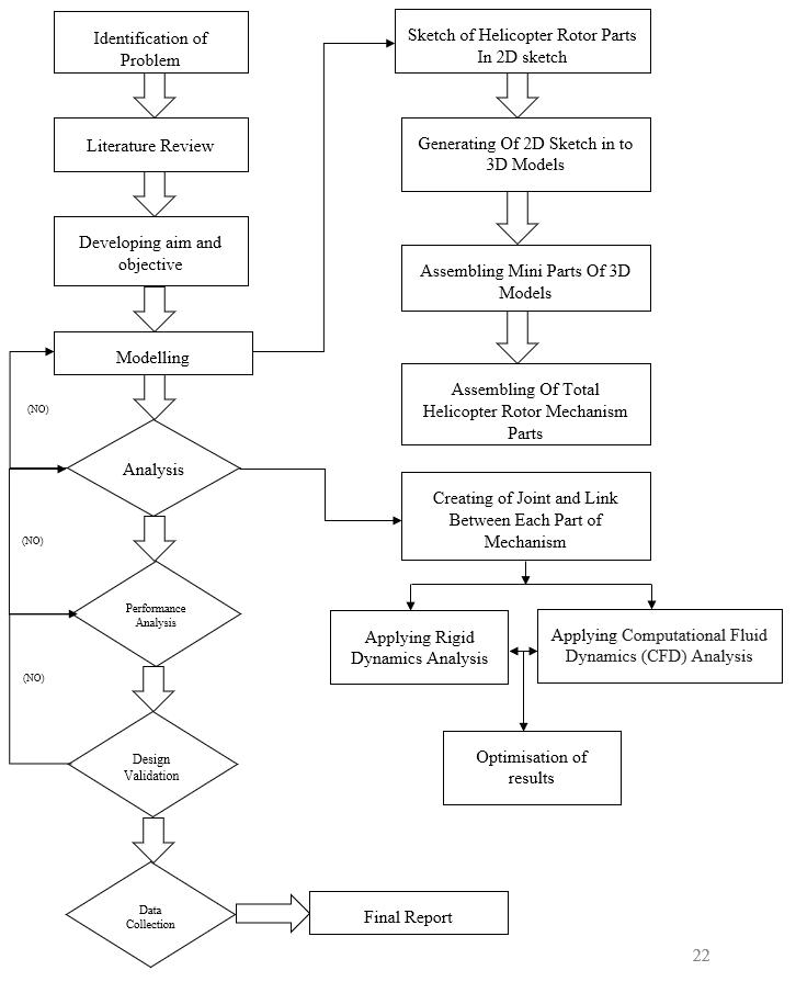
Literature Review: The potential of the project was acknowledged after referring to several research papers, whichalsohelpedintheproperdesignandanalysisprocess.
Developing aim and objective: To minimize the stress developed on the blades of the rotor, connecting rod, and scissor under different rotations per minute of the rotor speed.
International Research Journal of Engineering and Technology (IRJET) e ISSN: 2395 0056
Volume: 09 Issue: 08 | Aug 2022 www.irjet.net p ISSN: 2395 0072
Modeling: designingsoftwareSOLIDWORKSwasusedfor the designing of all the components in helicopter rotor mechanisms
Analysis: Analysisofthecomponentswasdonebyusing ANSYS software under Rigid Dynamics Analysis and ComputationalFluidDynamics(CFD)Analysis
Performance analysis: Byusingtheiterationmethodlarge number of iterations were performed and performance analysiswascarriedout.
Design validation: Thedatacollectedusingtheiterative method was used to finalize the design and respective changesweremadeinthemodelforbetterperformance.
Data collection: Togatherthemeasuringdata,andanalyze accuratedatafromavarietyofrelevantsourcesofanalysis
Final report: The project report is written evidence of tasks, processes, and activities that are undertaken and accomplished while pursuing their projects and implementingthemintheprojectwork
The helicopter rotor mechanics consists of different componentsinit.thesecomponentsareusedtoconstructof rotormechanism.Intheprocess,wehavefirstcreateda2D sketch of the components and these components are generated into 3D model parts from the 2D sketch. After designingthe3Dmodel,weassembledthepartsintoamini assembly by getting together small parts into a single assembly.Thenthesesingleassembliesareusedtocreatea major assembly of the helicopter rotor mechanism. These arethecomponentsusedinthehelicoptermechanism
3.1.1
LinkageBall
LinkageBall Extended
LinkageBall ForServoArm
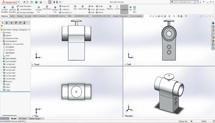
MainRotorHousing
MainShaft
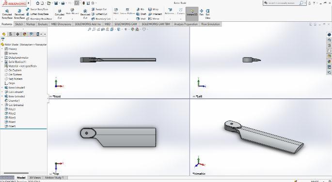
RotorBlade
RotorHolderArm
ServoMotor
UpperSwashConnector
UpperSwash
Fasteners
RotorHeadFasteners
HorizontalVerticalLinkFasteners
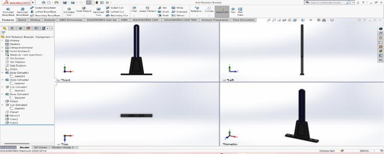
Theanti rotationbracketaccordingtothepresentinvention prevents rotating concerning an appliance in which it is installed. The bracket includes a U shaped member, an attachmentmechanismforsecuringtheU shapedmember toanappliance,andatleastoneclipextendingfromeachof twolegsoftheU shapedmemberforsecuringarectangular crimpedsectionofajoint.
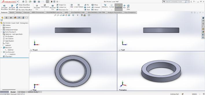
3.1.2
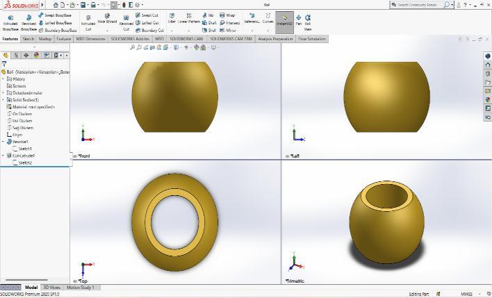
The ball holder's lower half is used to hold and allow to rotateinit.theballisattachedtothemainshaftoftherotor and it rotates concerning the main shaft of the helicopter. Theholderislikeadiskshape.Itislocatedbelowtheball andabovetheSwashplate
International Research Journal of Engineering and Technology (IRJET) e ISSN: 2395 0056
Volume: 09 Issue: 08 | Aug 2022 www.irjet.net p ISSN: 2395 0072
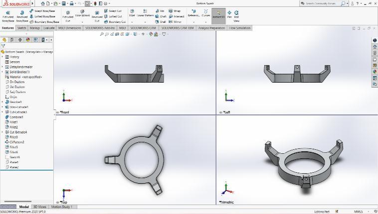
A swashplate is a device that translates input via the helicopterflightcontrolsintothemotionofthemainrotor blades. Because the main rotor blades are spinning, the swashplateisusedtotransmitthreeofthepilot'scommands fromthenon rotatingfuselagetotherotatingrotorhuband mainblades.
The ball joint is attached to the main shaft rotor of the helicopter mechanism. It is located between the two balls holder.Itrevolvesaroundthemainshaftspeedandhelpsto swashplatesnottorotatethemjusttomoveinthedirection
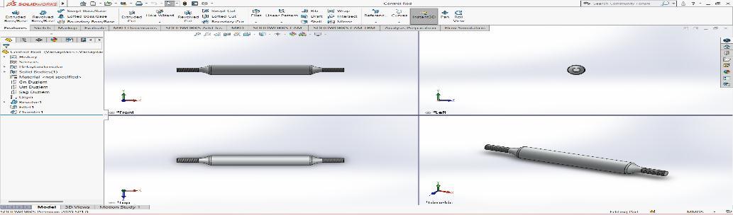
The control rod assembly has a control rod which is providedbetweenaswashplate sidebearingcenteranda rotor blade side bearing center. An axle housing has an eccentricstructurethatisaccommodatedinaswashplate side bearing center and a bearing structure that is accommodatedinaswashplate sidebearingblock.
Fig 3 Ball
The base is used to stabilize the mechanism. All the compoundsare assembledandtheseareheldonthe base platform.Thebaseprovidessupporttothemechanismand therotationofthemainshaftforthemechanism
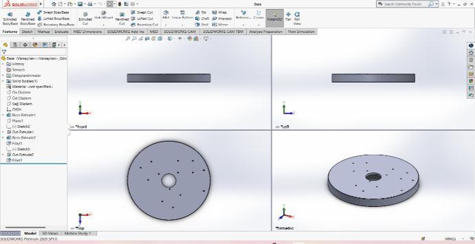
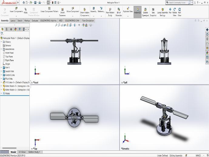
Ahelicoptermainrotororrotorsystemisthecombinationof several rotarywings(rotor blades)witha control system, thatgeneratestheaerodynamicliftforcethatsupportsthe weight of the helicopter, and the thrust that counteracts aerodynamicdraginforwardingflight.
Fig 4 Base
International Research Journal of Engineering and Technology (IRJET) e ISSN: 2395 0056
Volume: 09 Issue: 08 | Aug 2022 www.irjet.net p ISSN: 2395 0072
The blades of a helicopter are long, narrow airfoils with a high aspect ratio, a shape that minimizes drag from tip vortices. They generally contain a degree of washout that reduces the lift generated at the tips, where the airflow is fastest and vortex generation would be a significant problem.
5.1
Utilize the power of the rigid dynamics explicit solver for efficient and robust evaluation of mechanical systems containingcomplexassembliesofinterconnectedrigidparts undergoing large overall motion. Apply procedures for analysisofmachineandmechanismsystemssuchasvehicle suspensions,landinggearassemblies,roboticmanipulators, andenginecomponents.
5.1.1 Process of rigid dynamic analysis
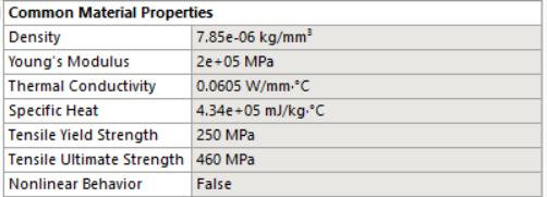
Engineering data is the data of the selected material properties,wehavechosenthestructuralsteelbecausethe mainconceptistotestthemechanisminAnsys.Itisadefault materialintheAnsysworkbench.Thefollowingfigureshows thepropertiesofthematerial
Open solidworks > file > click on assembly model > Go to assembly menu > click on insert components > select on Baseminiassembly>placeontheoriginpoint>clickOK> click on insert components > select on swash plate mini assembly>clickonmate>selectonrequiredmateforboth mini assembly > click OK > click on insert components > selectonControlRodminiassembly>clickonmate>select onrequiredmateforbothminiassembly>clickOK>click oninsertcomponents>selectonPitchminiassembly>click onmate>selectonrequiredmateforbothminiassembly> clickOK>clickoninsertcomponents>selectonHorizontal verticalminiassembly>clickonmate>selectonrequired mate for both mini assembly > click OK > click on insert components>selectonRotorBlade’s>clickonmate>select onrequiredmateforrotorholder>clickOK>clickoninsert components > select on Rotor Blade’s 2 > click on mate > selectonrequiredmateforrotorholder>clickOK
The geometry is the file import from the assembled helicopter mechanism in the Solidworks file which is convertedintotheSTPfileforamoreaccuratemodel,STP filemakesAnsysmeshtheobjectveryfinetogetthebetter results
International Research Journal of Engineering and Technology (IRJET) e ISSN: 2395 0056
Volume: 09 Issue: 08 | Aug 2022 www.irjet.net p ISSN: 2395 0072
Fig 11 mechanismGeometry
3. Model Model is the next step of the geometry which allows the geometrytoconstrainthejointwitheachlinkbyusingthe revolution joint, fixed link, cylindrical joint, and spherical joint which makes the parts move and rotate as the helicoptermotionlikealiftandland
Onceyouhaveyourphysicsdefinedyoumustcreateatwo or three dimensional geometry that is dependent on your problem analysis. Some problems are solvable in two dimensions, which can save time and money through reducedcomputationalneeds.WeusetheSolidworksdesign moduleinAnsys
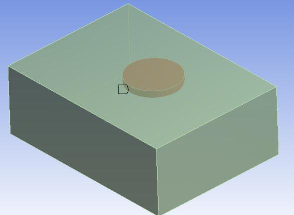
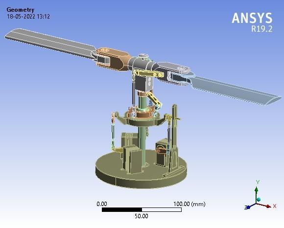
Fig 12 Modelofthemechanism
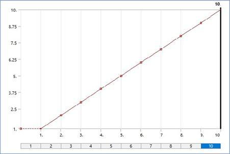
Afterassigningalljointconstraintstoeverypartthesetup isthenext.Wegivetherotationmagnitudetothejointas loadsandnoofstepsassigning
Table 1 SetupValues
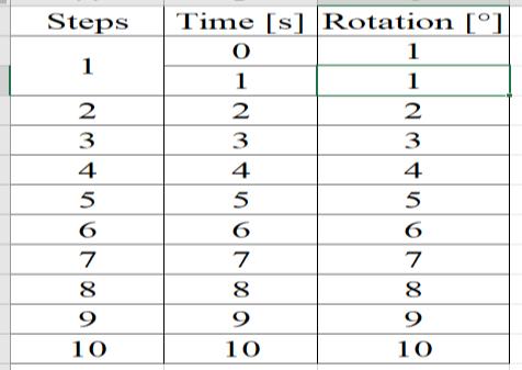
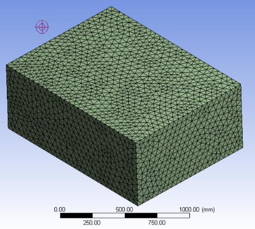
Fig 14 Geometryofrotor
Meshingrequiresagreatdealofcarebecauseitcanhave acascadingeffectonyouranalysisifdoneimproperly. Thisstepinvolvesestablishingthephysicaldomainof your environment into defined regionscalledcells,or controlvolumes.Thesecellsarefurtherdefinedbythe fluidflowequationsinsidethatgovernthem requiring thedesignertomakeaproperassumptionabouttheir flow profiles. Most designers find that keeping these cellsassmallaspossiblecanhelpyouensureaccuracy throughouttheanalysis
International Research Journal of Engineering and Technology (IRJET) e ISSN: 2395 0056
Volume: 09 Issue: 08 | Aug 2022 www.irjet.net p ISSN: 2395 0072
majorassemblyofthehelicopterrotormechanism.Wehave designedeverycomponentbyusingSolidworkssoftware.In Solidworks, we have used different entities to design and model a component Wefirstmodel simpleandindividual componentswithsomedesignstandardsthisarerelatedto the main component Then this component is attached to sub assemblies with related components this process will reducetheeffectontheconstructionofthemainassemblyto avoidconfusionandconstraintsintheassembly.Thenthese sub assemblies are together into a single assembly as the mainassembly.Hencethefinalhelicoptermechanismpartis assembledandhasamechanicalmovement.Wehaveused the Ansys software to test the mechanism with Rigid dynamicAnalysisandComputationalFluidDynamics(CFD) AnalysisResults
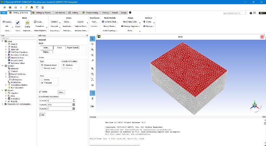
In this stage, we will have to define the conditions of the problems we want to solve. For example, transient one phase, stationary or multiphase, turbulence model, fluid type, and boundary conditions. It is essential to know the physicsoftheproblembecausethenumericalsolutionsare pre configured.Moreover,wehavetoknowhowthemethod works. When it comes to processing, we can choose the processorstouseandthenecessaryiterationswhenitcomes toachievingconvergence.
Theresultsonthemechanismandgotthetotaldeformation, totalvelocity,andtotalacceleration.ByusingRigiddynamic Analysis
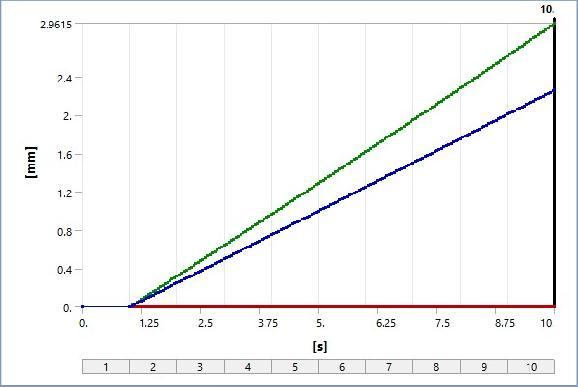
Total Deformation result
The helicopter rotor mechanics consists of different componentsinit.thesecomponentsareusedtoconstructof rotormechanism.Inthisprocess,wehavefirstcreateda2D sketch of the components and these components are generated into 3D model parts from the 2D sketch. After designingthe3Dmodel,weassembledthepartsintoamini assembly by getting together small parts into a single assembly.Thenthesesingleassembliesareusedtocreatea
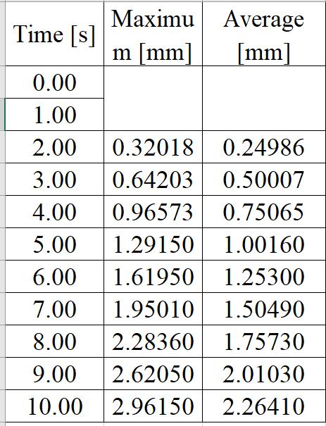
The above graph is shown the total deformation in the helicoptermechanismthedeformationtakesonthey axis and time in x the axis. the deformation will increase according to the time on the x axis the maximum and averagedeformationoccursat10secondsat2.96150mm and2.26410mm.thevaluesareshowninthetablebelow
International Research Journal of Engineering and Technology (IRJET) e ISSN: 2395 0056
Volume: 09 Issue: 08 | Aug 2022 www.irjet.net p ISSN: 2395 0072
Theabovestreamlineisinstraightlineflowthereareless turbulentflowsothereisaproperflowaccordingtoevery streamlineanditsownproperty’sandaccordingtothis thestreamlinesaremovedandshowed
Theabovegraphisshownthevelocityproberesultofrotor blade1inthehelicoptermechanismthevelocityprobetakes on the y axis and time in x the axis. the velocity will decreaseverygraduallyaccordingtothetimeonthex axis thedifferentaxisvelocityoccursat10secondsatthex axis is0.0010mm/sandonthey axisis0.01974mm/sandon thez axisis 0.04138mm/s
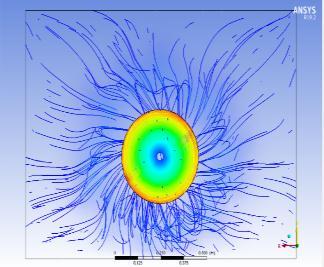
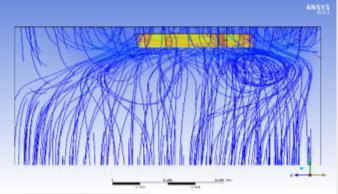
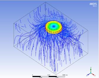
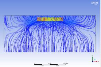
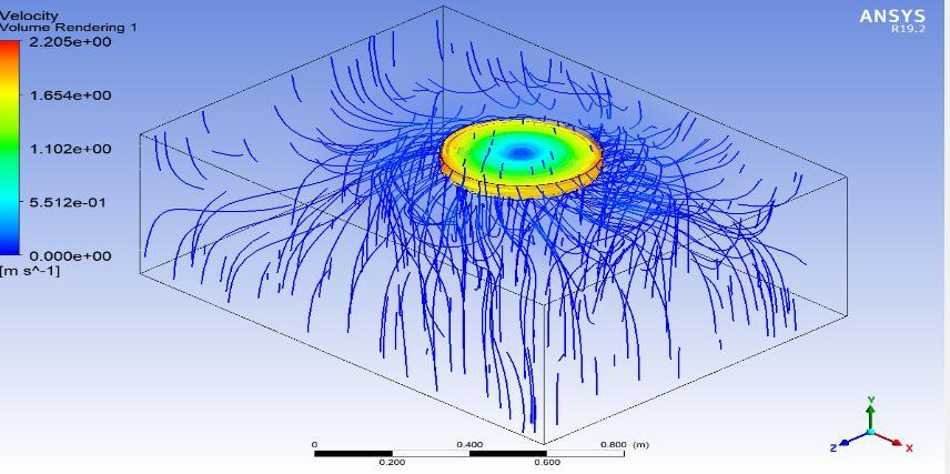
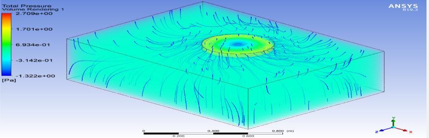
We have done the results on the rotor blades and got the streamline,densityofair,dynamicviscosityofair,velocity, totalpressure,velocityAxial,velocityRadial,andviewofthe flow.ByusingCFDanalysis
Intheabovevelocityresult.wehavegotamaximumvelocity of2.205m/sandaminimumvelocityof0.00m/s
In the above total pressure result. We have got maximum totalpressureof2.709Paandaminimumtotalpressureof 1.322Pa

International Research Journal of Engineering and Technology (IRJET) e ISSN: 2395 0056
Volume: 09 Issue: 08 | Aug 2022 www.irjet.net p ISSN: 2395 0072
Themaingoalwastofindthetotaldeformation,velocity,and accelerationwithreducingheavycomponentswhichimpact themainrotor.Withintheframeof analysis,aerodynamic computationanalysesweremade.Differentconfigurationsof themainrotorandflowconditionswereinvestigated.The obtained results may be very useful to design simple helicoptermechanics.Butthemostimportantreasonisto useofobtainedresultstofurtheranalysislikethedynamic analysis.Analysiswhichincludesbothstabilityofthemain rotor The global conclusion from this project is that the rotatingcomponentslikethemainrotorhaveabiginfluence onthestaticstability.
JAYANTH REDDY PINGILI, UG Student, Department of Mechanical Engineering, Guru Nanak Institute of Technology,Ibrahimpatnam,R.R.Dist 501506,India

GANGDHAR RAJU PEDDAMALLA, UG Student, Department of Mechanical Engineering, Guru Nanak Institute of Technology,Ibrahimpatnam,R.R.Dist 501506,India


RACHAKONDA KANAKARAJU, UG Student, Department of Mechanical Engineering, Guru Nanak Institute of Technology,Ibrahimpatnam,R.R.Dist 501506,India
2022, IRJET | Impact Factor value: 7.529 | ISO 9001:2008 Certified Journal