
International Research Journal of Engineering and Technology (IRJET) e-ISSN: 2395-0056
Volume: 12 Issue: 03 | Mar 2025 www.irjet.net p-ISSN: 2395-0072


International Research Journal of Engineering and Technology (IRJET) e-ISSN: 2395-0056
Volume: 12 Issue: 03 | Mar 2025 www.irjet.net p-ISSN: 2395-0072
NAGARAJ A2
1,2 Lecturer, Department of Mechanical Engineering, PSG Polytechnic College, TamilNadu, India
Abstract - This project focuses on the design and fabrication of a combined buffing machine that enhances multipurpose applications while improving production rates with high dimensional accuracy. Buffing, a metal polishing process, smoothens surfaces by rubbing with polishing particles on a rotating disk. Traditional manual buffing methods often result in inaccuracies, affecting surface finish andproductivity. Theproposedmachine integrateslinearand radial buffing techniques using a single motor, ensuring precise polishing with increased efficiency. A 0.25 HP, 1440 rpmAC motor rotates the workpiece, while a 90-watt, 60 rpm DC gear motor controls the buffing actuator. The machine frame, made of mild steel for durability, is supported by deep groove ball bearings for improved load handling and longevity. Gears facilitate the transmission of rotary motion and power. By automating buffing movements, this system eliminates small dimensional errors, enhances surface finish, andsignificantlyreducesprocessingtime.Itscost-effectiveness and efficiency make it a valuable innovation for industrial applications, benefiting both production and environmental sustainability.
Key Words: Buffing Machine, Dimensional Accuracy, Productivity,Errors,Sustainability
Nowadays,itisessential to continuouslyincrease theproductionratetoachievehigheroutputwithminimal humanintervention.Tomeetthesedemands,thereisaneed todevelop innovativemachinerythat enhancesefficiency. The buffing operation, primarily performed on the face of components, is similar to polishing and is aimed at improving surface finish. Currently, buffing is done by mounting a fine polishing disk on the spindle of a bench grinderandfeedingthisrotatingdiskagainstthejobsurface. Buffingistheprocessofcreatingasmoothandshinysurface by rubbing it or using chemical action, resulting in a significant specular reflection. Metal polishing is a multistageprocess.Thefirststagebeginswithroughpolishing, where material removal occurs, using progressively finer buffingwheelsuntilthedesiredfinishisachieved.
Thesecondstage,finepolishing,involvesminimalor negligiblematerialremovalandismainlyusedtoeliminate scratches from the specimen’s surface. Finally, etching is performed to reveal the microstructural features of the
polished specimen through selective chemical attack. A commonmisconceptionisthatabuffedsurfacealwayshasa mirror-brightfinish;however,mostmirror-brightfinishes are actually the result of a combination of polishing and buffing. Polishing serves multiple purposes, such as enhancinganitem’sappearance,preventingcontamination, removing oxidation, creating a reflective surface, and preventing corrosion. In metallography and metallurgy, polishing is used to achieve a flat, defect-free surface for examining a metal’s microstructure under a microscope. Silicon-basedpolishingpadsordiamondsolutionsareoften used in the process. Polishing stainless steel can also enhance its sanitary properties. In a buffing machine, the buffingwheelspinsathighspeedinaplaneperpendicularto thesurface being machined, ensuringsurface flatnessand maintainingtheparallelismofoppositesurfaces.Thedepth of cut is controlled by the sliding motion of the table on whichthebuffingmotorismounted.Thisslidingmechanism ensuresthattheentiresurfaceisevenlymachined.
In most industries, the buffing process is performed manually by hand, which affects the accuracy of the workpiece’s finish and dimensions. Manually buffed workpieces are more likely to be rejected or require rework,leadingtoincreasedproductiontime.
Some industries face challenges in buffing both radial andlinearcomponentswiththesamelevelofaccuracy inashorttime.Toachievehighprecisionforbothtypes of components, they often purchase two separate machines for each operation. This requires additional space and operators, ultimately increasing the company'scosts.
Tobuffthecomponentswithhighaccuracy.
Toreducetherejectionandreworkofworkpiece.
Toincreasetheproductiontime.
To implement combined form technique to increase productionrate.
Toreducethecostofthecompany.
Tobeapplicableinbuffingdifferentworkpieces.

International Research Journal of Engineering and Technology (IRJET) e-ISSN: 2395-0056
Volume: 12 Issue: 03 | Mar 2025 www.irjet.net p-ISSN: 2395-0072
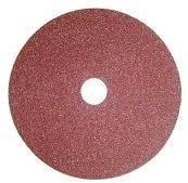
Polishingwheelscomeinawidevarietyoftypesto fulfil a wide range of needs. The most common materials usedforpolishingwheelsarewood,leather,canvas,cotton cloth, plastic, felt, paper, sheepskin, impregnated rubber, canvas composition, and wool leather and canvas are the most common. Hard roughing wheels can be made by cementing together strawboard paper disks. Softer paper wheelsaremadefromfeltpaper.
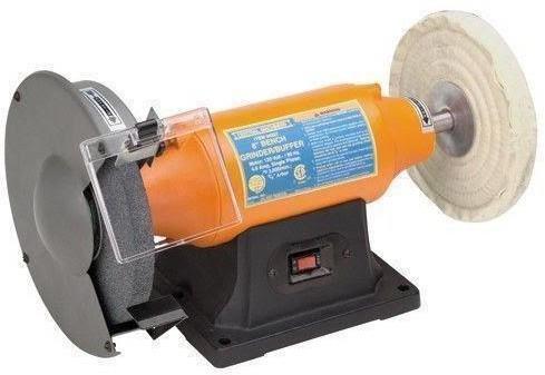
Thepolishingmachineisusedtopolishsoftmetals such as copper and brass, as well as plastics like Perspex. Thetwowheelsspinathighspeed,andwhenthematerialis carefullypressedagainstthemwhilemovingbackandforth, itachievesapolishedfinish.Beforepolishing,thematerial mustbefiledtoremovescratches,followedbytheuseofwet and dry sandpaper or emery cloth to further smooth the surface.
2.3
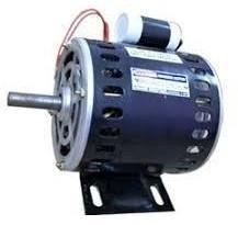
An electric motor is an electro-mechanical device that converts electrical energy into mechanical energy. In otherwords, a motor isa device thatgenerates rotational force.Theworkingprincipleofanelectricmotorisbasedon theinteractionbetweenmagneticandelectricfields.Electric motors are primarily classified into two types: AC motors andDCmotors.ACmotorsoperateusingalternatingcurrent, whileDCmotorsoperateusingdirectcurrent.
An AC motor is an electric motor powered by alternating current (AC). It typically consists of two main components:anexternalstatorwithcoilssuppliedwithAC togeneratearotatingmagneticfieldandaninternalrotor attached to the output shaft, which produces a second rotating magnetic field. The rotor’s magnetic field can be generated by permanent magnets, reluctance saliency, or DC/AC electrical windings. In this setup, the motor is mountedontheleftsideoftheframeandisusedtorotate theworkpieceduringthebuffingoperation.
2.3.2
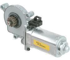
Thesesimplemotorshaveexcellentcharacteristics that make them suitable for a wide range of applications. They generally operate at low speeds but are capable of extremely high torque. Worm drives inherently provide a brakingfeatureduetotheirdesign.Additionally,theyoffer right-angle orleft-anglegearboxes, makingthempractical formountingintightspaces.Theonlysignificantdrawback of worm gear drives is their low efficiency. Even the best wormgeardriveshaveanefficiencyofonly60–80%.
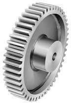
Spur gears, or straight-cut gears, are the simplest type of gear, consisting of a cylinder or disk with radially projectingteeth.Theymeshproperlyonlyonparallelshafts and generate no axial thrust. While efficient at moderate speeds, they become noisy at high speeds. Spur gears are

International Research Journal of Engineering and Technology (IRJET) e-ISSN: 2395-0056
Volume: 12 Issue: 03 | Mar 2025 www.irjet.net p-ISSN: 2395-0072
classifiedasexternalorinternal.Externalgearshaveteeth ontheoutersurfaceandcanmeshwitheitherexternalor internalgears,rotatinginoppositedirectionswhenpaired. Internalgearshaveteethontheinnersurfaceandonlymesh withexternalgears,rotatinginthesamedirection.Internal gear assemblies are more compact due to closer shaft positioning.
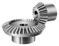
Abevelgearisatypeofgeartypicallymountedon shafts that are 90 degrees apart. These gears are used to changethedrivedirectionofagearsystemby90degrees. The tooth-bearing surfaces of bevel gears are conically shaped,andtheiraxesintersect.Instraightbevelgears,the pitch surface is conical, and the teeth are straight and taperedtowardtheapex.
2.6
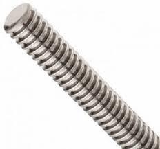
A lead screw, also known as a power screw or translation screw, is a mechanical component used to convert rotational motion into linear motion. Due to the large sliding contact area between the male and female threads, lead screws experience higher frictional energy losses compared to other linkages. They are typically not usedforhigh-powertransmissionbutaremoresuitablefor intermittent use in low-power actuator and positioner mechanisms.Commonapplicationsincludelinearactuators, machineslides,vices,presses,andjacks.
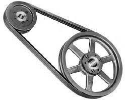
Apulleyisasmallfixedwheel,sometimesmounted inablock,withagroovedrimthatallowsaropeorchainto runthroughit.Itisusedtoraiseaweightbypullingonthe oppositeendoftherope.Asinglefixedpulleychanges the directionofeffortbutprovidesnomechanicaladvantage.A combination of multiple pulleys is used to increase mechanicaladvantage.Pulleyscanalsobeusedtotransmit powerwhenturnedbyabelt,rope,orchain.
A bearing is a machine element that restricts relativemotiontoaspecificdirectionwhilereducingfriction between moving parts. Its design may allow free linear movementofacomponent,freerotationaroundafixedaxis, orcontrolledmotionbymanagingthenormalforcevectors actingonthemovingparts.Bearingsarebroadlyclassified basedontheiroperation,thetypeofmotiontheypermit,or thedirectionoftheloadstheysupport.


International Research Journal of Engineering and Technology (IRJET) e-ISSN: 2395-0056
Volume: 12 Issue: 03 | Mar 2025 www.irjet.net p-ISSN: 2395-0072
3. SPECIFICATIONS OF COMPONENT
Table -1: ComponentsSpecification
Voltage 220V,Single Phase
ACMOTOR
DCGearMotor Input
220V,Single Phase
Buffing Actuating Motor
LeadScrew
LeadScrew andNut Mechanism
BevelGear Setup
BeltandPulley Drive
4. DESIGN OF THE BUFFING MACHINE
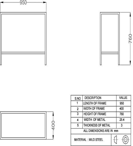
Fig -10:Frame
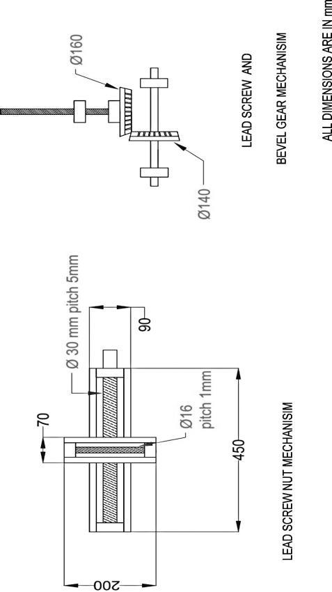
Fig -11:DesignofMechanism
5. DESIGN CALCULATIONS
5.1 TORQUE PRODUCED BY DC GEAR MOTOR

International Research Journal of Engineering and Technology (IRJET) e-ISSN: 2395-0056
Volume: 12 Issue: 03 | Mar 2025 www.irjet.net p-ISSN: 2395-0072
FORMULATOFINDTORQUE,
T=Power(P)/AngularVelocity(ω)
FORMULATOFINDANGULARVELOCITY,
ω=(2*Π*N)/60
=(2*π*60)/60
ω=6.28Rad/s
T=P/ω=90/6.28=14.32Nm
5.2 TORQUE PRODUCED BY BUFFING ACTUATING MOTOR
Given:
Power,P=0.5HPSpeed,N=3000rpm
FORMULATOFINDTORQUE,
T=Power(P)/AngularVelocity(ω)
FORMULATOFINDANGULARVELOCITY,
ω=(2*Π*N)/60
=(2*π*3000)/60
ω=314.16Rad/s
T=P/ω=372.85/314.16=1.18Nm
5.3 TORQUE PRODUCED BY AC MOTOR
Given:
Power,P=0.25HPSpeed,N=1440rpm
FORMULATOFINDTORQUE,
T=Power(P)/AngularVelocity(ω)
FORMULATOFINDANGULARVELOCITY,
ω=(2*Π*N)/60
=(2*π*1440)/60
ω=150.8Rad/s
T=P/ω=186.42/150.8=1.24Nm
5.4 SPEED OF LEAD SCREW
Given:
Speedofmotor=60rpm
No.ofteethongear1=72
No.ofteethongear2=8
GearRatio=1:9
SpeedofLeadScrew=Gearratio*Speedofmotor =(1/9)*60 =6.6=7Rpm
Testing is way to find errors and problems of the completed project. Testing is carried out to improve the qualityofacompletedproductorproject.Inourproject,list oftestingprocessiscarriedoutafterthecompletionofthe project.Theyare,
Testingofmotors.
Testingoflinearactuationmovement.
Testingofrotaryactuationmovement.
Testingofbuffingprocess.
Buffingprocessisametalpolishingprocess,whichenhances look of the product and removes burs and irregularities.
Buffingprocessiscarriedoutbytouchingthebuffingwheel againsttheworkpiecesurface.Therearetotallytwodifferent buffingprocessiscarriedoutthisproject,theyare
Linearbuffingprocess
Radialbuffingprocess
Linear buffing is a type of buffing process carried out in a linear direction, both forward and reverse. The linear actuation movement process has been explained earlier. During this movement, the workpiece undergoes buffing (i.e., polishing). In this linear buffing test, the effectiveness of buffing in a linear direction is evaluated. Oncetheworkpieceissecuredinthecoupling,itbeginsto rotate.Simultaneously,thebuffingactuatingmotormoves linearly.Therequiredpolishingdepthisadjustedmanually basedonthedesiredsurfacefinish.Duringthisprocess,the buffingperformanceiscarefullymonitored.
Theradialbuffingprocessisatypeofbuffingusedtocorrect runout in workpieces. Since runout occurs in a radial direction,thisprocessiscalledradialbuffing Radialbuffing is performed by keeping the buffing actuating motor in a fixedpositionwhileadjustingthedepthforpolishing. The workpiece rotates against the buffing wheel, allowing the buffingtotakeplace.Therotationoftheworkpieceisdriven by rotary actuation movement. This process is tested to evaluate the buffing effectiveness when the workpiece is rotatedagainstthespinningbuffingwheel.

Fig -12:BuffingMachine
Workpiecesoftenhavesurfaceinaccuraciesandburrs.This project effectively reduces these imperfections using a buffingmachine,resultinginasmoothandshinysurface.It alsoremovesscratchesfromthespecimen.Afterbuffing,no further machining is required, and the component can be

International Research Journal of Engineering and Technology (IRJET) e-ISSN: 2395-0056
Volume: 12 Issue: 03 | Mar 2025 www.irjet.net p-ISSN: 2395-0072
directlyusedinassembly.Additionally,thismachineensures parallelism between opposite faces, enhancing precision. Throughthisproject,weachievethedesiredsurfacefinish andeliminateirregularities.Finally,wewouldliketoexpress our gratitude to everyone involved in the development of thissystem,bothdirectlyandindirectly.Wealsoextendour sincere thanks to the department for their invaluable supportinbringingthisprojecttocompletion.Wehopethat this project successfully fulfills its intended purpose, demonstratingtheeffectivenessoftheprocess.
[1] BhaskarChandraKandpal;RajeshKumarVerma;Dalip Malhotra;AshishKumar;AnujKumar;MallikaTaneja,, “Cell Proliferation without Neurogenesis in Adult Primate Neocortex,” Science, vol. 294, Dec. 2001, pp. 2127-2130,doi:10.1126/science.1065467.
[2] Hosned, “A Construction of Polishing Machine CooperatingwithRobot”,Doc.Ing.VladimirAndric,Csc., 2014
[3] Leonard E. Samuels, “Metallographic polishing by mechanicalmethods”,ASMinternational,2003.
[4] I.D.Marinesce,H.K.Tonshoff&I.Inasaki,“Handbookof Grinding & Polishing”, Noyes Publications/ William AndrewPolishing,LLC.,2000.
[5] “Design Data Book”, PSG College of Technology, Coimbatore,KalaikathirAchagam,2016.