
Volume: 12 Issue: 03 | Mar 2025 www.irjet.net
International Research Journal of Engineering and Technology (IRJET) e-ISSN: 2395-0056 p-ISSN: 2395-0072

Volume: 12 Issue: 03 | Mar 2025 www.irjet.net
International Research Journal of Engineering and Technology (IRJET) e-ISSN: 2395-0056 p-ISSN: 2395-0072

Dr.S.Venkatesan , Mahima Vishali R , Arivumathi P, Madhu Mitha M , Mr. A. Marimuthu
Department of Electrical and Electronics Engineering, K.L.N. College Of Engineering, Pottapalayam, Sivagangai, Tamil Nadu, India
Abstract - This paper presents the design and analysis of a cascaded buck-boost converter for electric vehicle battery charging. The converter enhances efficiency, reduces inductor current ripple, and achieves fast switching speeds, ideal for high-performance applications. MATLAB simulations with closed-loop control and PWM generation show significant improvements in ripple reduction and faster switching speeds, validatingthe potential of the cascaded buck-boost converter in modern EV charging systems.
Key Words: Electric Vehicle (EV), Cascaded buck-boost converter (CBB) Photo Voltaic (PV), Maximum power point tracking (MPPT), Inductor current ripple reduction, Fast switching speed, MATLAB simulation, Closed-loop control (CLC), Pulse Width Modulation (PWM) generation, Renewableenergytechnologies.
Thisprojectaimstodevelopanoff-boardEVbatterycharger using grid electricity and solar power. Leveraging India's solar resources, the initiative promotes decentralized electricitygeneration.IntegratingsolarPVtechnologywith EVchargingstationsencouragesenergyindependenceand reducesrelianceonfossilfuels.Thesystem'sautomaticbuck and boost configuration enhances energy management, ensuring a reliable energy supply even during grid fluctuations.SimulationsinMATLABvalidatethefeasibility of this Cascaded Buck-Boost converter (CBB), marking a significant advancement in EV charging technology and renewableenergyutilization.
Photovoltaic(PV)generationoffersadvantageslikenofuel costs, low maintenance, and no pollution. However, PV moduleshavelowefficiency,necessitatingahigh-efficiency power conditioning system (PCS). A single-phase PV PCS consistsofDC-DCandDC-ACconversionstages.TheDC-DC convertercontrolsmaximumpowerpointtracking(MPPT) via duty ratio modulation. Though commonly used, the Cuckoo algorithm has limitations. A cascaded converter improves efficiency for high-power applications, reducing conductionlossandvoltageripple.Theproposedtopology predictstheoptimaldutyratiobasedonsolarirradiation. MATLAB simulations with closed-loop control and

WM generation enhance performance. Initially, power is sourcedfromthegrid,convertedto12VDC,andboostedto 24Vifneeded.Afour-channelrelayselectsthebestpower source,interfacing with an Arduino Nano for regulation. The cascaded converter maintains constant voltage, reducing ripple and switching loss. This project demonstrates the advantages of using a cascaded buck-boostconverterforPVmodules,improvingefficiency andperformance.
The primary objectives of this study are to design, to analyze the performance of a Cascaded Buck & Boost converterusingaPVpanel.Todeveloptheprototypemodel oftheCascadedBuck&Boostconverter.Thisapproachnot only enhances system efficiency but also guarantees a dependablepowersupplyfordiverseapplications,withthe outputpowerutilizedforbatterycharging.
AcomparisonbetweenaconventionalDC-DCconverter and a cascaded Buck & Boost converter is done based on various parameters like manual feedback, input current ripple&outputvoltageripple.Themainaimistoobtaina high-accuracyconverterwithreducedinputcurrentripple andreducedoutputvoltagerippleasshowninTable1.
The cascaded converter provides continuous load output. For higher current applications, it is preferable. It will improve the efficiency and reduce the maintenance needed for any photovoltaic system. It provides a faster switchingspeedandreducesinductorcurrentripple.

Volume: 12 Issue: 03 | Mar 2025 www.irjet.net
International Research Journal of Engineering and Technology (IRJET) e-ISSN: 2395-0056 p-ISSN: 2395-0072
Table-1: ComparisonbetweenconventionalDC-DC converterandcascadedBuck&Boostconverter
S.No Conventional BuckBoost Converter Cascaded Buck-Boost Converter
1 Efficiencyislow Improvedefficiency
2 BuckorBoost conversionworksin eitheronetopology SimultaneousBuck Boostoperationis achieved
3 Increaseininductor currentripple ReducedInductor currentripple
4 Slowswitchingspeed Fastswitchingspeed
The conventional DC-DC converter faces limitations like input/outputrippleandefficiency.TheCascadedBuck-Boost (CBB)converteraddressestheseissues,offeringhigh-gain conversion,reducedripple,andbetterperformanceforEV charging systems. Its design enhances voltage boost/buck capabilities, making it ideal for high step-up/down power conversion.
3.1 Limitations of the existing system
The existing system's limitations impact efficiency andreliability.Firstly,thetotalcurrentflowingthrougha single switch increases voltage stress. Additionally, high input ripple current and output voltage ripples cause performance issues. Significant switching losses lead to inefficientenergyuse,andoverallvoltagestabilityislow, makingthesystemlessreliable.Thesefactorscollectively limiteffectivenessandefficiency,highlightingtheneedfor improvements.
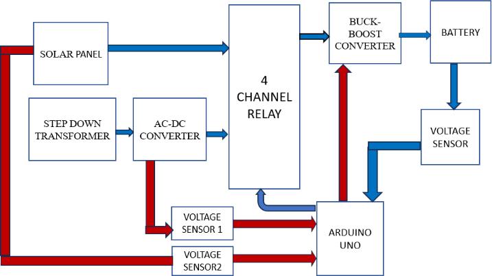
Thecascadedbuck&boostconceptisusedinthisworkto obtainnoninvertingoutputtoruntheconstantDCloadas showninFig.1.Thedesignequationshavebeenpresented, and performance parameters have been related using theoretical calculations and simulation. The operation principle and steady-state performance are analyzed and finally, the experimental results are given, moreover, the derivationoftheproposedconverterisalsopresented.
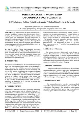
Initially,powerissourcedfromthegridandroutedthrough astep-downtransformertoconvertthe230VACvoltageto 12VAC.Subsequently,a12VACto12VDCconversionis achieved using an AC-DC Converter. A 12 V solar panel is employed,withaboostconverterenhancingthevoltageto 24Vwhennecessary.Outputsfromboththesolarpaneland the step-down transformer are directed to a four-channel relay.Therelayinterfaceswithavoltageandcurrentsensing circuit, as well as an Arduino Nano for regulation and control. The relay selects the best power source that is available and disables another source. The relay output is connectedtovoltagevoltage-sensingcircuittomeasureand modifythevoltage.Theoutputfromthefour-channelrelayis connected to the cascaded buck-boost converter, which bucksorboostautomaticallythevoltageifthevoltagelevel decreasesorincreasesfromthesolarpanelorgridmakingit constant and preventing it from varying. The converter is connectedtothebatterywhichchargesfromthecascaded converterandithasavoltagesensortocheckiftherequired voltage is achieved. The Arduino governs the circuit operationsandinitiatesthesignalingprocess.Adedicated circuit for voltage and current sensing measures these parametersfrombothsourcesfordisplaypurposes.Utilizing Arduinocode,thesystemselectsthepowersourcewiththe highervoltage.Valuescanbemonitoredviaaserialmonitor oranLCD.Theoutputvoltagereceivedcanbeusedtocharge theloadthroughthebattery.
Fig 3 shows the circuit diagram of a cascaded BuckBoostconverterandTable1showstheComparisonbetween aconventionalDC-DCconverterwithacascadedbuck-boost converter.
International Research Journal of Engineering and
Volume: 12 Issue: 03 | Mar 2025 www.irjet.net
-3: CircuitDiagramofCBBconverter
4.2. Selection of Converter Components
1. Input voltage ranges:
InputVoltage Vin(min) = 8.00V
InputVoltage Vin(max) = 11.0V
InputVoltage Vin(avg) =9.50V
2. Output voltage & current ranges:
OutputVoltageVo(Boost) =12.0V
OutputVoltageVo(Buck) =4.0V
OutputCurrentIo =1.0A
3. Calculation of Duty Cycle (Boost):
10.

(IRJET) e-ISSN: 2395-0056 p-ISSN: 2395-0072


Table-2: Hardwarespecifications

DutyCycle D1 = =20.83%
4. Calculation of Duty Cycle (Buck): DutyCycle D2 = =42.10%

5. Calculation of inductor (Boost):
Inductance L1 = = 564µH

6. Calculation of inductor (Buck):
Inductance L2 = =78H

7. Calculation of inductor ripples current (Boost): InductorRippleCurrent ΔI (L1) =
to40%ofIo =0.03A
8. Calculation of inductor ripples current (Buck): InductorRippleCurrent
6. SIMULATION ANALYSIS
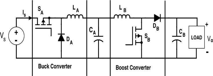
ThisprojectoutlinesthecircuitdesignoftheCascadedBuckBoost converter-based controller, including a solar panel, voltagemeasurementcircuit,andcascadedconverterdesign withMOSFETswitches.TheMATLABmodelconsistsof
Volume: 12 Issue: 03 | Mar 2025 www.irjet.net
International Research Journal of Engineering and Technology (IRJET) e-ISSN: 2395-0056 p-ISSN: 2395-0072
inductors,outputcapacitors,blockingdiodes,andresistive loads.Forverification,simulationsweredonewitha7.5Ω resistiveload,1.5mHinductors,500μFoutputcapacitors,a 10kHzswitchingfrequency,anda1e−6samplingtime.The systemoperatesinBuckmodewhentheinputis24Vandthe referenceis12V,andBoostmodewhentheinputis12Vand referenceis24V,adjustingthedutycycleaccordingly.
-4: MATLABModelofCascadedConverter
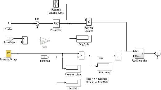
-5: Closedloopbuck-boostcontrollerblock
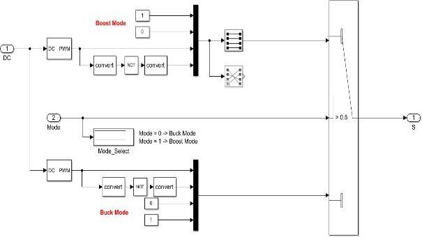
-6: PWMgenerationblock
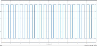
Fig -7: PWMsignals
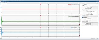
Fig -8: Inputvoltage,current,andpowerduring Boostoperation.
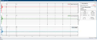
Fig -9: Outputvoltage,current,andpowerduring Boostoperation.
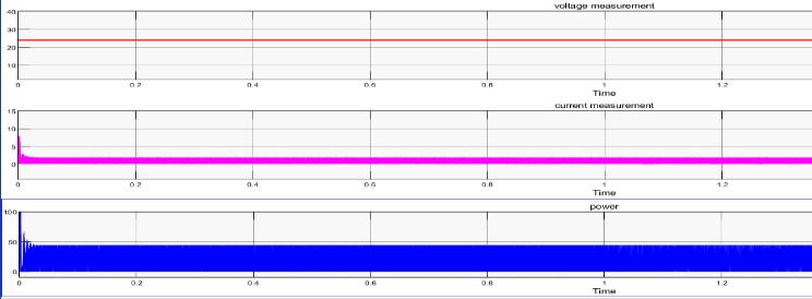
Fig -10: Inputvoltage,current,andpowerduring Buckoperation.
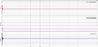
Fig -11: Outputvoltage,current,andpowerduring Buckoperation.
Whenvaryingtheinputvoltageofthesolarpanelmanually usingapotentiometerfrom(8-12)Vtheconstantoutputof 12V is given by the converter in order to maintain the constantvoltageforthebatterycharging.Ifthevoltageofthe batteriesdropsbelow20v,thebatterywon'tgetcharged. Since we developed the prototype model of the Cascaded converter, we can also verify the results using MATLAB Simulation.
Research
Volume: 12 Issue: 03 | Mar 2025 www.irjet.net
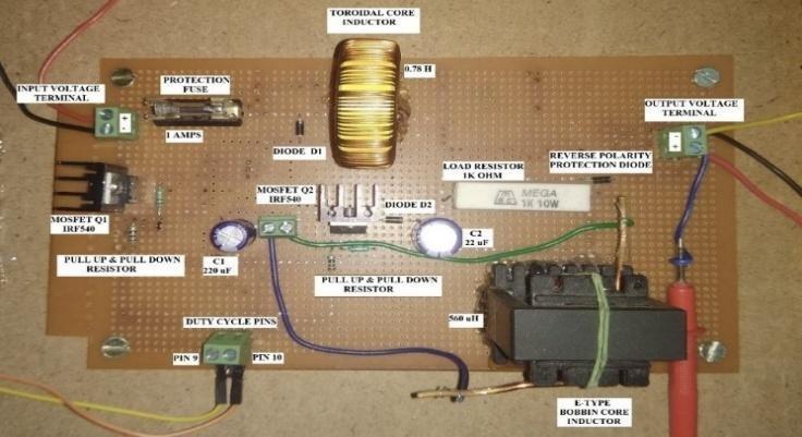
-12: CascadedBuck-Boostconverter
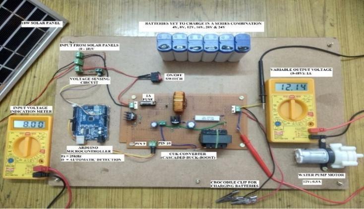
Fig -13: Inputvoltage8.00Vwithconstant12V outputvoltage

Fig -14: Inputvoltage12Vwithconstant8V outputvoltage
8. RESULT
Thefollowingtabulationsshowtheresultsfromhardware systemvalidationandsimulationresultsfromMATLAB.As we can see in both cases, we get the constant DC voltage requiredforchargingthebattery.Thisworkincreasesthe efficiencyofthesystem,reducesinductorripplecurrent,and providesafasterswitchingspeed.
Table-3: InputOutputTabulationofHardware Implementation
Table-4: Resultsfromthesimulation

The project aims to harness solar energy for charging EV batteries. Solar energy is a renewable and abundant resource, significantly reducing greenhouse gas emissions comparedtotraditionalfossilfuels.Byutilizingsolarpower, theprojectnotonlysupportstheadoptionofcleanenergy butalsomakesEVchargingmoreaffordableforconsumers, thereby encouraging the widespread use of sustainable energysources.
Volume: 12 Issue: 03 | Mar 2025 www.irjet.net
International Research Journal of Engineering and Technology (IRJET) e-ISSN: 2395-0056 p-ISSN: 2395-0072
Encouraging the use of electric vehicles (EVs) supports cleaner and more sustainable urban development. EVs produce zero tailpipe emissions, leading to improved air qualityandreducednoisepollutionincities.Byreducingthe carbonfootprintoftransportation,theprojectcontributesto thedevelopmentofsmartandsustainablecities.
Reducing dependence on fossil fuels through the use of renewable energy sources helps mitigate climate change. The project addresses the urgent need to cut down on greenhouse gas emissions by promoting the use of solar energyforEVcharging.
Promotingresourceandenergyefficiencywithintheproject fosters sustainable consumption and production patterns. The use of solar energy for EV charging minimizes the depletion of non-renewable resources and reduces environmentalimpact.Theprojectencouragesresponsible use of resources by optimizing energy consumption and promotingsustainableproductionpractices.
In this work, a Cascaded Converter was designed and the simulationresultsobtainedfortheproposedsystemandthe performanceofthesamearevalidatedusingexperimental results[6].Theperformanceoftheconverterwasanalyzed usingprototypebybothbuck&boostoperationwhererated inputvoltageofsolarpanelvaluefrom(8-12)Visboostedto 12V,16V&24Vthenalsoreducedto4V&8Vunder1kΩ load condition to charge the battery. In conclusion, EV chargingisanessentialaspectofelectricvehicleownership andthetransitiontosustainabletransportation.
[1] K. Punitha, V. Seetharaman, D. Devaraj, and V. Selvaganesh,“Deeplearning basedmaximumpowerpoint prediction for Arduino controlled solar water pumping systems”, Songklanakarin J. Sci. Technol. 44 (3), 884–891, May–Jun.2022.SCOPUSindexed.
[2]L.Callegaro,M.Ciobotaru,J.E.Fletcher,P.A.RiosandD.J. Pagano, "Design of cascaded control loop for solar power optimizerbasedonabuck-boostconverter,"2016IEEE2nd Annual Southern Power Electronics Conference (SPEC), Auckland, New Zealand, 2016, pp. 1-6, doi: 10.1109/SPEC.2016.7846136.
[4] Manivannan S and Kaleeswaran E, "Solar powered electric vehicle," 2016 First International Conference on Sustainable Green Buildings and Communities (SGBC), Chennai, India, 2016, pp. 1-4, doi: 10.1109/SGBC.2016.7936074.
[5] S. K. Goyal, G. Gangil and A. Saraswat, "Simulation of Solar-GridChargingofElectricVehicleusingPIController," 20222ndInternationalConferenceonInnovativePractices inTechnologyandManagement(ICIPTM),GautamBuddha Nagar, India, 2022, pp. 247-252, doi: 10.1109/ICIPTM54933.2022.9754003.
[6]Y.Kassem,H.Gokcekus,andA.Aljatlawe,“Utilizationof Solar Energy for Electric Vehicle Charging and the Energy ConsumptionofResidentialBuildingsinNorthernCyprus:A CaseStudy”,Eng.Technol.Appl.Sci.Res.,vol.13,no.5,pp. 11598–11607,Oct.2023.
[3] S. Maitreya, H. S. Dangi, N. S. Naruka and P. Paliwal, "AnalysisofSolarPoweredElectricVehicles,"2021IEEE2nd International Conference On Electrical Power and Energy Systems (ICEPES), Bhopal, India, 2021, 10.1109/ICEPES52894.2021.9699596.pp.1-4. © 2025, IRJET | Impact Factor value: 8.315 |