International Research Journal of Engineering and Technology (IRJET) e ISSN: 2395 0056

Volume: 09 Issue: 07 | July 2022 www.irjet.net p ISSN: 2395 0072
International Research Journal of Engineering and Technology (IRJET) e ISSN: 2395 0056
Volume: 09 Issue: 07 | July 2022 www.irjet.net p ISSN: 2395 0072
1 , Robert Benham2
1Associate Professor, Faculty of Creative Industries, Architecture and Engineering, Solent University, Southampton, UK
2Senior Lecturer, Faculty of Creative Industries, Architecture and Engineering, Solent University, Southampton, UK ***
Abstract Additive Manufacturing is emerging as a cost
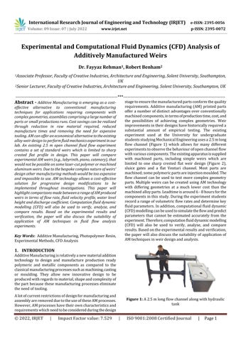
 effective alternative to conventional manufacturing techniques for applications requiring components with complexgeometries,assembliescomprisingalargenumberof parts or small productions runs. Cost savings can be realized through reduction in raw material required, reduced manufacture times and removing the need for expensive tooling.AMcanofferaneconomicalalternativetotheexisting alloyweirdesigntoperformfluidmechanicsexperimentinour lab An existing 2.5 m open channel fluid flow experiment contains a set of standard weirs which is limited to sharp crested flat profile in design. This paper will compare experimentalAM weirs (e.g.,labyrinth,piano,catenary),that wouldnotbepossibleonsomelaser cutpolymerormachined aluminum weirs. Due to the bespoke complex nature of weirs’ design other manufacturing methods would be too expensive and impossible to use. AM technology allows a cost effective solution for progressive design modifications to be implemented throughout investigations. This paper will highlightcomparisonsmadebetweenarangeofAMproduced weirs in terms of flow rate, fluid velocity profile, water level height and discharge coefficient. Computation fluid dynamic modelling (CFD) will also be used to verify, analyze, and compare results. Based on the experimental results and verification, the paper will also discuss the suitability of application of AM techniques in fluid flow analysis experiments.
Key Words: AdditiveManufacturing,PhotopolymerResin, ExperimentalMethods,CFDAnalysis
AdditiveManufacturingisrelativelyanewmaterialaddition technology to design and manufacture production ready polymeric and metallic components as compared to the classicalmanufacturingprocessessuchasmachining,casting or moulding. They allow new innovative design to be producedwithregardstomaterial,shapeandcomplexityof thepart becausethesemanufacturingprocesseseliminate theneedoftooling.
Alotofcurrentrestrictionsofdesignformanufacturingand assemblyareremovedduetotheuseoftheseAMprocesses. However,AMprocesseshavetheirowncharacteristicsand requirementswhichneedtobeconsideredduringthedesign
stagetoensurethemanufacturedpartsconformthequality requirements. Additive manufacturing (AM) printed parts offera number of distinct advantagesover conventionally machinedcomponents,intermsofproductiontime,cost,and the possibilities of achieving complex geometries. Weir improvementsintheirdesignshavehistoricallyrequireda substantial amount of empirical testing The existing experiment used at the University for undergraduate studentsstudyingMechanicalEngineeringusesa2.5mlong flow channel (Figure 1) which allows for many different experimentstoobservethebehaviourofopenchannelflow withvariouscomponents.Theexistingapparatusissupplied with machined parts, including simple weirs which are limited to one sharp crested flat weir design (Figure 2), sluice gates and a flat Venturi channel. Most parts are machined;somepolymericpartsareinjectionmoulded.The flow channel can be used to test more complex geometry parts. Multiple weirs can be created using AM technology with differing geometries at a much lower cost than the machinedalloyparts.Leadtimeisaround6 8hoursforthe componentsinthisstudy.Duringtheexperimentstudents recordarangeofvolumetricflowratesanddeterminekey fluidparameters.Inaddition,computationalfluiddynamic (CFD)modellingcanbeusedtosimulatetheflowandpredict parameters that cannot be estimated accurately from the experiment.Therefore,computationfluiddynamicmodelling (CFD) will also be used to verify, analyse, and compare results.Basedontheexperimentalresultsandverification, the paper will alsodiscussthesuitabilityofapplication of AMtechniquesinweirdesignandanalysis.
Figure 1: A2.5mlongflowchannelalongwithhydraulic tank
International Research Journal of Engineering and Technology (IRJET) e ISSN: 2395 0056
Volume: 09 Issue: 07 | July 2022 www.irjet.net p ISSN: 2395 0072
Duetothelimitedtimeandpreliminarytesting,thenumber ofweirswasrestrictedtofourdesignmodelsthatcouldbe comparedtothesuppliedmachinedsharp crestedweir.The weirs selected for this study include two with a catenary crest(oneemptyandonerampedinFigure3),alabyrinth weir and a piano key type weir (Figure 4) New weirs (Figure 5) are made from tough additive manufacturing polymer,likeABS,atranslucentplastictypecommercially available photopolymer resin using a Stereolithography (SLA)AMmachine.
The procedure for performing the experiment is outlined below:
Theflowchannelisconnectedtothehydraulictankand anangleof0.5°(entrylevelhigherthanexitlevel).The internaldimensionsofthechannelwererecorded(53 mmwidex120mmdeep).
Thepumpisswitchedonandsettomaximumflow.
Theheightofthewaterlevelisrecordedatdesignated positions along the channel, 200 mm apart. These positionsremainconstantoncetheweirsareinserted.
A pitot tube connected to a data logger is used to measure the velocity of the fluid over 20 second intervals.Statisticstoolsgivethemean,maximumand minimum values. The process is repeated twice to checkconsistencyofreadings.
Thevolumetricflowrate wasrecordedbytimingthe tank to fill to 35 litre capacity. From the data, the velocity is calculated (and compared), the Reynolds number,Froudenumberaswellasflowrates.
Each weir independently is then inserted 1800 mm fromtheentryend,andstages2 5repeated.
Twoflowrateswereused:maximumflow(tomimicflood conditions)andminimumflow(ensuringfullcoverageofthe weirwall).Thedatumfortakingheightmeasurementswas thetopoftheflowchannelanddepthtothewaterlevelwas measuredbyadepthgauge.Pointsweremeasuredat200 mmintervalsclosetotheweirupstreamand600mmfrom theweirdownstream.Apitottubeconnectedtoadatalogger wasusedtomeasurethevelocityandarepresentativevalue was recorded at each of the measuring points using the statisticstoolover20 secondtimeperiods.
Theexperimentprocedureisrepeatedforminimalflow (ensuringwatercoverageonthewallsoftheweir).
Each weir had a flat crest; further research will look at variationsincrestprofile. Theflowchannelwasrunempty and recorded when set at 0.5° at full flow. A number of parameters were calculated, such as volumetric flow rate, averagevelocity,theReynoldsnumber,Froudenumber.The weirs were then tested at maximum flow rate and then a reducedflowratesothattherangeinupstreamheightcould be calculated and the weirs could be compared under different flow conditions. Computational Fluid Dynamic (CFD)modellingbasedonflowsimulationwascarriedout
International Research Journal of Engineering and Technology (IRJET) e ISSN: 2395 0056
Volume: 09 Issue: 07 | July 2022 www.irjet.net p ISSN: 2395 0072
usingtheactualflowrates,sothatthevariationsinvelocity profilecouldbeseenandregionsofinterestestablished. Aspreadsheetwasusedtocomputetheflowrates,Froude andReynoldsnumbersaswellascarryoutcomparisonsto the supplied (machined) sharp crested weir. The main comparisonfactorsusedaretheaverageheightofthewater marksupstream;thedifferencesinwaterheightsbetween the maximum and minimum flow rates; the discharge enhancement ratio, referred to here as the “r” value (see equation1);themass flowrateratioofdischargebetween the upstream and downstream and the mass flow rate downstream. CFD modelling was used to compare the calculated the parameters and in addition observe the velocityprofilesatregionsinthechannelsuchastheweir approach,thecrest,nappe,andothersectionsofthechannel farawayfromtheweir.
A spreadsheet (Table 1) was used to compute important resultsparametersfordifferentflowrates.
Table 1: DataCollectionfordifferentflowrates
One factor that limits the testing of weirs is the relatively narrowwidthoftheavailableflowchannel(53mm).Alotof research employs wider channels, although the results overallshowthattheAMweirshadgoodconsistencyforthe upstreamwaterheightamaximumflow.Oneproblemwith geometryoftheweirscoupledwiththeparameterswasto tryanddeterminethecoefficientofdischargeaccurately.As mentionedbyseveralauthors,notablyKumaretal(2020) thedeterminationoftheseparametersiscomplicatedoften requiresdifferentmodellingapproaches.Unlikethesharp crestedweirthathasarelativelystraightforwardformulato calculate the coefficient of discharge, Cd, the other weirs couldbecomparedinsteadbythedischargeenhancement ratio: (1)
3.3.
For a sharp crested weir (Figure 6), the computation of dischargeiscalculated
Initialtestingoftheweirsshowedveryclearlythatvariation in upstream height between the maximum and minimum flowrateswasmuchlowerthanthesharp crestedweir.For maximumflow rate, thesimplecatenaryweirexhibitsthe best combined properties. The comparisons (Table 2) are relativelysimple.Thelabyrinthweirscoredthelowestinall parametersapartfromaverageheightofwaterupstream
minimum (reduced) flow rate, again the catenary remainsthebettermodelhoweverthecomparisons(Table
International Research Journal of Engineering and Technology (IRJET) e ISSN: 2395 0056
Volume: 09 Issue: 07 | July 2022 www.irjet.net p ISSN: 2395 0072
3) are more complicated. The piano key weir does not performinmajorityofparameterssuchasaverageheightof waterupstream,Coefficientofdischargeandmaximumflow rate.
channels.Labyrinthweirsareattractedalotofinterestdue totheirrelativelylongexistenceandwidespreaduse;studies by Crookston, Paxson and Campbell (2013) do compare severalgeometricalfactorsandincludea2 cyclelabyrinth weirtoothers.
Anotheraspectthatcanbeeasilycomparedisthegradientof the water line over the side length of the weir, and the difference in forms of nappes at the flow rates for both empty (Figure 7) and ramped (Figure 8) catenary type of weirsatfullflowrate.
Figure 9: Side onviewofthelabyrinthweiratfullflow rate.
A logical next step in this research would be compare differentcrestprofiles(e.g.,sharp,flat,quarter round,half round, ogee). The catenary shape derived from the hyperboliccosinefunction(coshx)waschosenbyauthors due to the relatively long crest that can be achieved in a relativelynarrowchannel.
One issue that could be improved in terms of design for testingAMpartsisreducingthesidewallandundersome weirs, this was most noticeable with the piano key weir (Figure10).Themosteffectiveweirpreventingthiswasthe rampedcatenaryweir,duetotheincreasedrigidityofthe model.
Figure 7: Side onviewoftheemptycatenaryweiratfull flowrate.
Figure 8: Side onviewoftherampedcatenaryweiratfull flowrate.
The labyrinth (Figure 9) weir did not compare well in on mostofthecomparisoncriteriaforbothflowrates,however the major limitation of only having two cycles meant that weircharacteristicsareunlikelytobesimilarformuchwider
Figure 10: Side onviewofthepianokeyweiratfullflow rate.
Thepianokeyweir(figure10)designwasbasedonsimilar designratioparametersfromotherresearch(Erpicumetal), andathighflow ratesscoredwell.Themostconsistent in terms of ranking over all comparators is the ramped catenary, in third place at maximum flow but second at lowestflow.Theerrorofthepitottubewasevaluatedinthe empty channel, where velocity was calculated from the volumetricflowrate.Itwasfoundtobe96%accurate,from thereadingstaken.
International Research Journal of Engineering and Technology (IRJET) e ISSN: 2395 0056
Volume: 09 Issue: 07 | July 2022 www.irjet.net p ISSN: 2395 0072
Although results show consistency, however following experimentalissueswereencountered:
Thechannelisrelativelynarrow,limitingthenumberof repeatingsectionsoftheweir.
Therampedcatenaryweirhadtheoptimumrigidityand requiredtheleastrubbermountsupport.Thepianokey wastheleaststable.
Side leakage and floor leakage were observed on all weirs;thepianokeyshowedconsiderablesideleakage.
The pitot tube position had to be securely fixed, otherwiseconsiderablevariationwasprobable.
Limitedtimeonlyallowedforafewweirstobetested forthisresearch.
Only flat crest profiles were tested for the initial research.Thisprofileisnotoptimum.
Thecoefficientofdischargeiseasytocalculateforthe sharp crested weir but more complicated for other weirs. The narrow channel problem means that the coefficientislikelytobeverydifferentforamuchwider channelwithmorerepeatingsections.
As an alternative the “r” value was measured (Q test weir/Qsharp crestedweir).
Finite Element Analysis based CFD flow simulations were done to evaluate and compare the flow dynamics results obtainedfromexperimentaldataforallfourdifferenttypes of weirs The fluid flow pattern observed through CFD analysisofempty(Figure11)catenary,ramped(Figure12) catenary, labyrinth (Figure 13) and piano key (Figure 14) weirsisalmostlikeexperimentalflowpattern.
Simulationresultsalsoverifiedandcomparedtheaverage velocitiesobtainedfromexperimentaldataforbothempty and ramped catenary weirs shown in Table 4. Change in shape from empty to ramped shaped weir results in negligiblereductioninaveragevelocitiesfromCFDanalysis
Simulationanalysiswasalsoveryusefulforregionsthatare difficult to measure with the pitot tube and boundaries withinthesystem.
International Research Journal of Engineering and Technology (IRJET) e ISSN: 2395 0056
Volume: 09 Issue: 07 | July 2022 www.irjet.net p ISSN: 2395 0072
Table 4: ComparisonofExperimental/SimulationDatafor averagevelocitiesinbothcatenaryweirs.
TypeofCatenaryWeir ExperimentalAverage Velocity(m/sec)
CFDAverageVelocity (m/sec)
Empty 0.650 0.628
Ramped 0.650 0.627
Overallresultsyieldfollowingkeypoints:
Thescopeforfurthertestingisgreat.Theresultsin this small study show the potential of a catenary shapedweirs,howeverothercharacteristicsneedto beconsidered,suchascoefficientofdischarge.
AMweirsarelighterthanthesuppliedmetallicones and do need supporting mounts. The side and bottom leakage could not be measured. Reducing this is important before further work can commence.
AMpartstookaround6 8 hourstoproduceand cost around £12 each. By introducing complex profiles,thisdoesnotalterthesevaluesverymuch. Severalpartscanbeproducedinoneperiod. Some AM profiles could not be produced by conventional methods on aluminum alloys or Perspex models. The tough AM SLA resin is well suitedtothisapplication.
DurabilityforsomeAMpolymerscouldbeanissue, howevernoneofthosetestedraisedanyconcerns andthesewillbeusedagain.
The research shows that effective weir designs can be implementedandcomparedusingsuitableAMtechnologies. The tough AM SLA resin performs well although the flexibilityinsomedesignsrequiresfurtherstructuralrigidity around the base to prevent the deformation of the shape when held in the channel. The catenary weirs show promisingresultshowevertheregionsofinterferenceneed tobestudiedfurther,andextrafeaturescouldbeaddedto tryandreducethedetrimentalfactorsonperformance.For example,nappebreakershavebeenexperimentedwithin several studies, Bilan et al (2018), and AM can allow for more complex geometries to be investigated. Further investigationisrequiredpriortothistocomparedifferent formsofcrest,astheflatcrestisnotoptimal.Inconjunction withthis,coefficientsofdischargeneedtobemathematically determinedandcomparedtothemeasuredflowratesover theweir.Thevolumetricflowratescanthenbecompared against the changes in height upstream to give a better comparison. The relatively narrow channel does limit the amountofworkthatcanbecarriedout;however,theresults showthatevenwithflatcrestedweirsthevariationinweir designcanbeeffectivelycomparedbyusingAMtechnology, which can give a good advantage over other construction methodsofmodelweirsforopenchannelflowstudies. Overall,fromthisstudy,wecanconcludethat
TheadvantagesofAMareclearinthisstudy:huge reductionsinlead timesandveryeconomicalparts canbeproduced.
Resultsareconsistentandrepeatabilitywasgood. Alimitednumberofweirsweretested.Thereisa huge scope of weirs that could be experimented with, but the next step is to vary the crest profile (e.g.,rounded,ogee).
To achieve optimization, weirs in wider test flow channelsshouldbetested.AMmodelscanbemade in sections and slotted together to accommodate largerwidths.
Thenextstagesaretolookatflowinduceddesign optimisation
[1] FormLabs tough and durable material, Formlabs material, 2022, https://formlabs.com/uk/materials/tough-durable/ , [Assessedon01June,2022].
[2] Kumar,M.,Sihag,P.,Tiwari,N.K.,&Ranjan,S.(2020). Experimentalstudyandmodellingdischargecoefficient oftrapezoidalandrectangularpianokeyweirs.Applied WaterScience,10(1),1 9.
[3] Crookston, B., Paxson, G., & Campbell, D. (2013). Effective spillways: Harmonizing labyrinth weir hydraulicefficiencyandprojectrequirements.Labyrinth andPianoKeyWeirsII,283.
[4] Erpicumetal,LabyrinthandPianoKeyWeirs.(2011). UnitedKingdom:Taylor&Francis.
[5] Bilhan,O.,Emiroglu,M.E.,Miller,C.J.,&Ulas,M.(2018). The evaluation of the effect of nappe breakers on the discharge capacity of trapezoidal labyrinth weirs by ELM and SVR approaches. Flow Measurement and Instrumentation,64,71 82.
“Dr. Fayyaz Rehman is an Associate Professor at Warsash School of Maritime Science and Engineering,SolentUniversity,UK. HeisaFellowofHigherEducation Academy, a Chartered Engineer fromtheEngineeringCouncilanda Fellow of the Institution of Engineering Designers, UK. He is also vice chair and committee member of the Consortium of UK ManufacturingEngineeringHeads (COMEH), a UK based body responsible for promoting manufacturing engineering educationandresearch,aswellas organizing the International Conference on Manufacturing Research(ICMR)conferenceseries
International Research Journal of Engineering and Technology (IRJET) e ISSN: 2395 0056
Volume: 09 Issue: 07 | July 2022 www.irjet.net p ISSN: 2395 0072
annually.Hisresearchinterestsare CAD/CAM/CAE, Material Testing and Additive Manufacturing Technologies.”
“Rob Benham isaseniorlecturer in engineering science and currently course leader for the HNCEngineeringandFoundation Year Engineering. He has been teachingonengineeringcoursesat SolentUniversityforover15years Prior to the introduction of individual course leaders, he was programme leader on the old engineering programme. In 2003 Rob completed his PGCE (post compulsory education) at Oxford BrookesUniversity.Hethentaught in further education for one additionalyear.Hecontinuedsome FE teaching and supply teaching when working part time. In addition to this, in more recent times, Rob has delivered many tasterdaysatSolent.Hehasstrong research interests in manufacturingandmaterials.Asa result, he brings a wide range of experienceofeducationalsettings withadiversescopeoflearners.”
2022, IRJET | Impact Factor value: 7.529 | ISO 9001:2008 Certified Journal