International Research Journal of Engineering and Technology (IRJET) e ISSN: 2395 0056


International Research Journal of Engineering and Technology (IRJET) e ISSN: 2395 0056
Vinithaasri. S1, D. Sri Vidhya2
1M. E. Power Systems Engineering, K. S. Rangasamy College of Technology, Tiruchengode, Tamil Nadu 637 215, India.
2Associate Professor /EEE, K. S. Rangasamy College of Technology,Tiruchengode, Tamil Nadu 637 215, India. ***
Abstract Sensorless BLDC motors are widely used in householdappliances,vehicles,aircraft,consumerelectronics, medical devices, automated industrial equipment, and instrumentation. Because of their design, these motors are employed in a variety of industrial areas. Sensorless BLDC motors are popular due to their increased efficiency, reliability, power, acoustic noise, smaller size, lighter weight, greater dynamic response, enhanced speed vs load torque, wider speed range, and extended life. It offers a number of advantages, including the elimination of the motor's neutral voltage, a predetermined phase shift network, a low starting speed, and a low cost. This study use MATLAB SIMULINK to give a straightforward and dependable method for detecting reverse emf zero crossings for sensorless operation. An abstract summarizes, in one paragraph (usually), the major aspects of the entire paper in the following prescribed sequence. The zero crossings of the reverse emf are projected obliquely from the terminal voltages that are monitored in relation to the dc negative pole, and thus approach never involves any integration. Furthermore, when using line voltages, neutral potential and common mode noise are no longer needed. Through simulation, the efficiency of the control strategy based on zero crossing detection from terminal voltage differences was studied.
Key Words: Sensorless operation, Zero Crossing Detector, Reverse EMF, Speed control method, Brushless DC Motor
Ithasseveraladvantages,includingtheeliminationofmotor neutral voltage, a set phase shift circuit, a low beginning speed,andinexpensivecost.Insteadofbrushes,thisBLDC motoriscommutatedelectronicallyusingpowerswitches. Thevoltagesurgesarecausedbytheremainingcurrentthat is restricted when power switches produce armature current.IntheconditionofsensorlessBLDCmotordriving, commutation torque ripple has already been reduced. Analysis,design,andimplementationofahigh performance sensorless method for BLDC motors are completed. BLDC motorsalsoreferredtoasPermanentMagnetDirectCurrent Synchronous motorsare still one of the motor types that have grown in popularity in recent years, owing to their superiorfeaturesandperformance.TheBLDCmotor,which lacks position and speed sensors, has received a lot of interest.Squarewavecontrolandsinusoidalcurrentcontrol arethetwomostcommonBLDCmotorcontroltechniques.
To calculate the zero crossing time of the reverse emf, multiplytheterminalvoltageofthefloatingwindingbythe motor'sneutralpoint.Integrationbeginswhenthereverse emfcrosseszeroandendswhenthegiventhresholdvalueis reached,resultinginimmediatecommutation.Frequency independent phase shifter for sensorless BLDC motor control, capable of shifting the zero crossing point of the inputsignal witha defined phasedelay.JungandHa have developed an extended Kalman filter estimator for a brushlessdcmotortoestimatespeedandrotorposition.The rotorpositionisobtainedindirectlybysensingthereverse emffromoneamongthethreemotorterminalvoltagesofa three phase motor. The necessity to establish the right values for the covariance matrix parameters, which represent the errors in modeling and measurements, is a barrier to using the extended Kalman filter technique for rotor position estimation. Sensorless control techniques basedonthereverseemf'sZeroCrossPoint(ZCP)havebeen widelyemployedinlow costapplications.Thezero crossing detector(ZCD)detectstheZCPofthereverseemf,andthe pulseiscreatedbymoving30°fromtheZCP.WhentheBLDC motorisatrestoratzerospeed,thereverseemfcannotbe calculatedusingtheZCPtechnique.
Asaresult,auniquecontrolisrequiredforthesmoothand dependable sensorless control operation of BLDC motors. Furthermore, the intricacies of sensorless motor starting were not discussed. However, the direct commutation instantdetectionapproachsuggestedlackstheflexibilityto advance the commutation instant, which may be implementedutilizingreverseemfzero crossingdetection techniques.Bymeasuringthemotorterminalvoltages,we devisedandconstructedanintegratedcircuitenablingthe sensorless operation of a BLDC motor. Frequency independent phase shifter for sensorless BLDC motor control, capable of shifting the zero crossing point of the inputsignalwithadefinedphasedelay.Forspeedandrotor positionestimation,anextendedKalmanfilterestimatorfor abrushlessdcmotorhasbeencreated.commutationinstant boosts torque generation, especially in high speed BLDC motoroperating.Thetechniqueofzero crossingdetection was utilized to start the BLDC machine successfully in sensorlessmode.Theconceptisdevelopedinthispaperto presentasimplerunningmodealgorithm.Inthispaper,we presentasimpleandreliableapproachfordetectingreverse emf zero crossings in sensorless operation using MATLAB/SIMULINK, as well as hardware implementation usingDSP.DSPisrequiredinhardwarecircuitstogenerate
Volume: 09 Issue: 06 | Jun 2022 www.irjet.net p ISSN: 2395 0072 © 2022, IRJET | Impact Factor value: 7.529 | ISO 9001:2008 Certified Journal |
International Research Journal of Engineering and Technology (IRJET) e ISSN: 2395 0056
Volume: 09 Issue: 06 | Jun 2022 www.irjet.net p ISSN: 2395 0072
therightmomentforpulseproduction.Thezerocrossingsof the reverse emf are approximated indirectly from the terminal voltages measured concerning the dc negative terminal, and no integration is required. Moreover, when linevoltagesareemployed,neutralpotentialandcommon mode noise are no longer required. Along with this BLDC motormodel,thedynamicbehaviorofthemotor,including no load,load,andloadtransients,hasbeeninvestigated.The efficiencyofthesensorlesscontroldetectionandlocalization of zero crossing via terminal voltage differences has been studiedusingsimulation.
Theterminalvoltagewaveformissubstantiallyidenticalto the reverse EMF waveform. The terminal voltages, rather than the reverse EMFs, can be employed to detect the commutation points of the BLDC motor in the proposed sensorlesscontrol.Astherotorspeedincreases,sodoesthe phaselag'spercentagecontributiontotheentireperiod.The latencywilldisruptthecurrentalignmentwiththereverse EMF,causingmajorissueswithhigh speedcomputation.The phase lag in commutation can induce substantial pulsing torques in such drives, which can cause rotor speed oscillations and excessive copper losses. The cut off frequencyoftheLPFisestablishedat2.5kHzinthisresearch bytakingintoaccountboththephaselagandtheharmonic dispersionofthereverse EMF.Thehysteresiscomparatoris usedtocorrectforthephaselagofthereverse EMFscaused by the LPF to establish the optimal inverter commutation sequence based on rotor position. Furthermore, high frequency ripples in the terminal voltages can avoid numerousoutputtransitions.
Thetraditionalstart upprocedureshowscertainunforeseen limitationsthatmayaffecttheBLDCmotor'sperformance. Tocircumventtheseconstraints,asimplestart upapproach is given that not only achieves the highest starting motor torquebutalsocontrolsthestatorcurrent.Unliketheusual technique, which only excites two stator windings, the suggestedstart upschemeexcitesalltriostatorwindingsby employing a specified starting voltage vector. The voltage vector V3 is orthogonal to Vi and is positioned between voltagevectorsV1andV2.Itisselectedasthenextapplied voltage vector to maximize starting motor torque during startup.Itshouldbenoticedthatbyvaryingthepulsewidth oftheswitchingdevices,theamplitudeofthestatorcurrent foralignmentoftherotorpositionmaybesimplymodified. Showsthethree phasecurrentresponsesoftheBLDCmotor whentheswitchisturnedonandthepulsewidthsofthetwo switches B and C are modulated at the same time. PWM signal duty cycles when the switching period Ts is 100 μ seconds. The size of the stator current can be readily controlled by modifying the duty cycle, which can be determined by taking the initial torque required at
value:
alignment into account. According to the rotor position beforealignment,themotormayrevolveinreverseduring alignment.However,becausethemaximumreverserotation angle is just 90 mechanical degrees, it does not affect fuel pumpoperation.Aftertherotorpositionhasbeenaligned, thestart upmethodisconsideredforacceleratingtheBLDC motorfromastandstilltoacertainspeed,3000rpm,whichis aminimumspeedfortheautomobilefuelpumpapplication. Becausethesensorlessschemedoesnotstartonitsown,the motor must be started and brought to a particular speed wherethezero crossingpositionofthereverse EMFmaybe detected.
The paper is to develop a sensorless brushless DC (BLDC) motor control system. Sensorless techniques based on a hysteresiscomparisonandapossiblestart upmethodwitha high beginning torque are proposed. The hysteresis comparatorcompensatesforthephasedelayofthereverse EMFscausedbyalow passfilter(LPF)whilealsopreventing numerousoutputtransitionscausedbynoiseorfluctuationin theterminalvoltages.Therotorpositionismaintainedatrest forthegreateststartingtorquewithouttheneedforanextra sensororanymotorparameterinformation.
Theproposedsystemconsistsofthevoltagesourceinverter receiving the direct current voltage. The voltage source inverterisathree phasevoltagesourceinverterwitha120 degreemodeofoperation.Itcomprisesthreelegs,eachof which contains two MOSFETs. In all, six MOSFETs are employedinthevoltagesourceinverter.MOSFETsareMetal Oxide Semiconductor Field Effect Transistors. It is the voltage control device's switching device. If we adjust the Vgs (Gate Source Voltage), we get a sinusoidal pulse with modulationsignals.WecanregulatetheVds(DrainSource Voltage),whichistheoutputvoltage.Inducedviachanging modulation.Itisdefinedastheratioofthereferencesignal voltagetothecarriedsignalvoltage.Inmyapplication,the reference signal is a three phase sinusoidal signal with a displacement of 120 degree and the carrier signal is a triangularsignal.TheinverterwillsupplypowertotheBLDC motorbyadjustingthemodulation.
International Research Journal of Engineering and Technology (IRJET) e ISSN: 2395 0056
Volume: 09 Issue: 06 | Jun 2022 www.irjet.net p ISSN: 2395 0072
AsaresultofFaraday'slaw,reverseemfwillbeinducedin thestatorwinding.Asaresult,thisreturnemfwillbeinthe oppositedirectionasthesourcevoltage.So,ifwecandetect this reverse emf, we can feed it into the hysteresis comparator.However,thereverseemfformistrapezoidal becauseof themotor'ssalientpolerotor.Wecan'treadily distinguish"0"and"1"inthistrapezoidalreverseemf.Asa result,thereverseemfprovidedtotheLPFwillbeconverted from trapezoidal to sinusoidal. This is passed on to the hysteresis comparator. The hysteresis comparator is the difference between the upper and lower values. It is an alternatingcurrentmotor witha statorsimilartoa three phase induction motor. The rotor is comprised of a permanentmagnetwithfourpoles(projectedPole)Itlacks rotorwinding,mechanicalcommutator,andbrushes,yetits speed torqueconstantissimilartothatofaDCshuntmotor. ThisisreferredtoasaBLDCmotor.Toprovidepowertothe motor stator winding, an electronic commutator (voltage source)inverterisemployed.
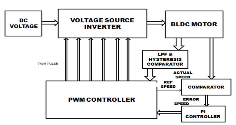
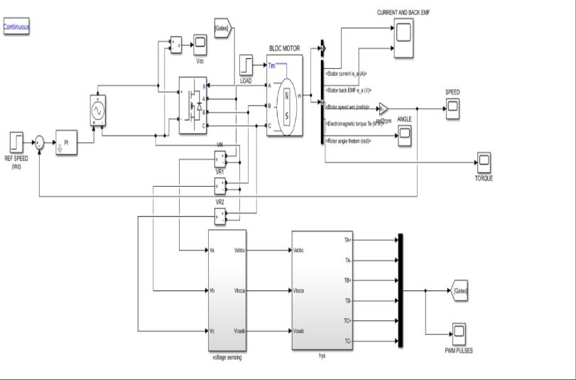
The voltage source inverter receives the input DC voltage andconvertsittoACvoltage.Togeneratethereverseemf,a sinusoidalV/FcontrolPWMapproachisappliedtotheBLDC motor,causingthemotortostartasaninductionmotor.This emf is detected using a voltage sensor, and the voltage is passed to the hysteresis comparator. The hysteresis comparatordetermineswhichwindingshouldbeenergized first;thiscomparatorcomparestheEMFsoftwophasesand generatesPWMpulses;thesepulsesarefedtotheinverter, andtheinvertersuppliesvoltagetothemotor;however,the voltagesensorproducestrapezoidalreverseemf,andwhen thistrapezoidal reverseemfisfedtothelowpassfilter,it produces sinusoidal reverse emf. The hysteresis current controllercomparestheactualmotorcurrentandreferences currentwaveforms;thedifferenceisoutputasPWMpulses by the current controller. The voltage source inverter receivesthispulse.
Fig 2: SimulationofSensorlessBLDCMotor
Table 1: SampleTableformat
Parameters
Motorrating 1.5Hp Ratedtorque 2.5N m
Typeofmotor BLDCMotor Supplyvoltage 420V Ratedspeed 4630rpm
Ratedcurrent 5A
The inverter will supply voltage to the motor, reducing statorcurrent.Sensorlesscontrolisachievedbytheuseofa hysteresis comparator approach, which includes LPFs for suppressing high switching frequency ripples, hysteresis comparatorsforcreatingthree phasecommutationsignals, and a gating signals generator for generating six Pulses. Whendetectingthethree phaseterminalvoltages,eachone is fed into an LPF to reduce the high switching frequency fluctuationornoise.BecausetheBLDCmotoronlyhastwo phasesactivatedatanygivenmoment,theback EMFmaybe determinedfromitsterminalvoltageinthedurationofan openphase(60°).Theonlyvariationbetweenthereverse EMF and its terminal voltage throughout the two phase conductionperiod(120°)isastatorimpedancevoltagedrop, whichmaybenegligiblewhencomparedtotheDCvoltage source.Thesensorlessmethodinverterwillsupplyvoltage tothemotor,reducingstatorcurrent.Sensorlesscontrolis achieved by the use of a hysteresis comparator approach, which includes LPFs for suppressing high switching frequencyripples,hysteresiscomparatorsforcreatingthree phasecommutationsignals,andagatingsignalsgenerator for generating six Pulses. When detecting the three phase terminalvoltages,eachoneisfedintoanLPFtoreducethe highswitchingfrequencyfluctuationornoise.Becausethe BLDC motor only has two phases activated at any given moment,theback EMFmaybedeterminedfromitsterminal
International Research Journal of Engineering and Technology (IRJET) e ISSN: 2395 0056
Volume: 09 Issue: 06 | Jun 2022 www.irjet.net p ISSN: 2395 0072
voltage in the duration of an open phase (60°). The only variationbetweenthereverse EMFanditsterminalvoltage throughout the two phase conduction period (120°) is a stator impedance voltage drop, which may be negligible when compared to the DC voltage source. The sensorless methodissimulatedinMATLAB/SIMULINKinfig.2.
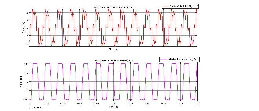
Intheproposedsystem,thesimulated graphofBLDCcurrentandBackEmfshowsthatinitially themotorstartfromnegativevalueof 2Aandafter steadilyattainsitspeakcurrentof2.5Aforthetimeof 0.005s.Thetotalamplitudeofthecurrentis5Aandits timeperiodfor1cycleis0.02seconds.IntheBLDCBack EMF,amplitudeoftheBackEMFis100vforthetime periodof0.005sand0.02sforfullcyclehasshowninthe fig.3.
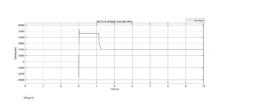
Inthemotorspeedwaveform,theinitialspeedofBLDC motoris500rpmattimet=0andthefinalspeedisrated to2000rpmattimet=4.25shasshowninfig.4.
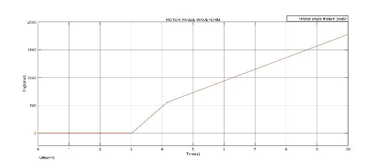
Fromtherotoranglewaveform,therotoranglestartsrising fromthetimeof3sanditgetsreachedupto1777.75atthe timeof10shasshowninfig.8.
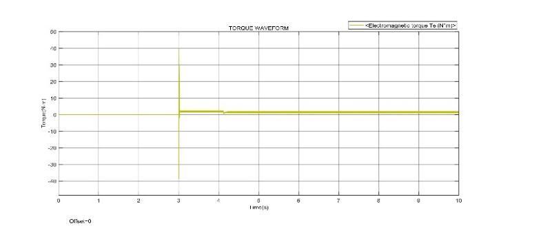
In the torque waveform, the initial minimum value is 38.7205 N m and the maximum value is 40.27 N m. The constant peak value of torque is 2.5 N m and minimum constantvalueis1.32N mhasshowninfig.5.
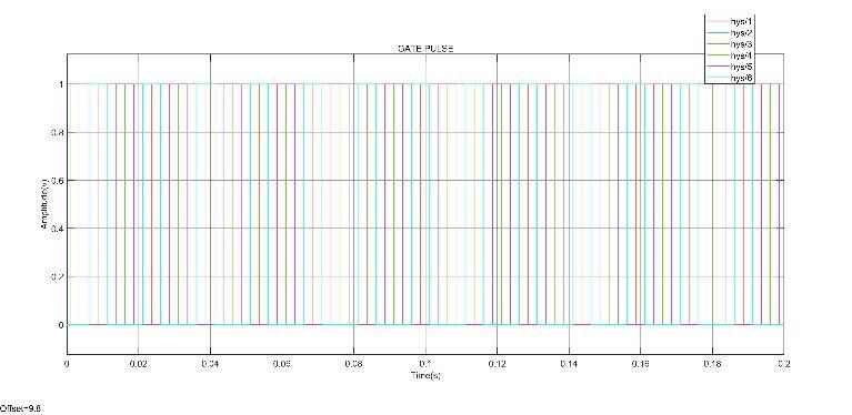
FromthePWMpulsegenerator,thegatepulseifvalue1 startsgeneratedafterthetimeperiodof3sinfig.6.
Thedcvoltageis283.329vatinitiallyanditgetspeakvalue of500v.Aconstantvoltageis214.5afterthetimeperiodof 4..3shasshowninfig.7
International Research Journal of Engineering and Technology (IRJET) e ISSN: 2395 0056
Volume: 09 Issue: 06 | Jun 2022 www.irjet.net p ISSN: 2395 0072
[1] Bharathi Sankar A and Dr.Seyezhai R (2014), “Sensorless Control of BLDC Motor using Back EMF basedDetectionMethod”.,IJEE,Vol. No.6,IssueNo.02.
[2] CarlsonRandMilchelL.M(1992),“Analysisoftorque ripple due to phase commutation in brushless dc machines”, IEEE Trans. Ind. Appl., Vol. 28, No. 3, pp. 632 638
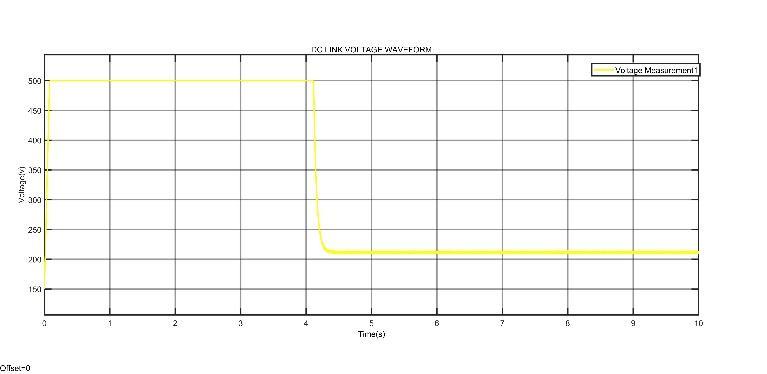
Fig 7: DCLinkVoltage
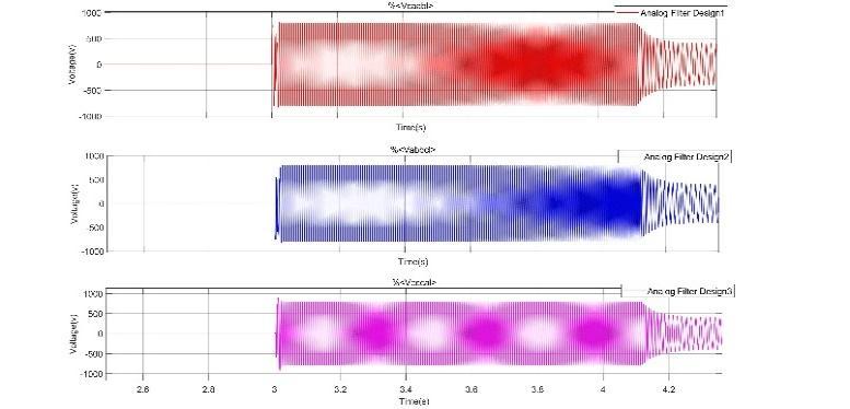
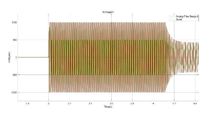
Thevoltageiscomparedbyhysteresiscomparatorblock andtheirwaveformsareshowninfig.8and9
[3] Kim D.K and Lee K.W (2006), “Commutation torque ripple reduction in a position sensorless brushless dc motordrive”,IEEETrans.PowerElectron.,Vol.21,No.6, pp.1762 1768.
[4] LiuYandHoweD(2007),“Commutationtorqueripple minimizationindirect torque controlledPMbrushless dcdrives”,IEEETrans.Ind.Electron.,Vol.43,No.4,pp. 1012 1021.
[5] Merin John and Vinu Thomas (2014), “Position Sensorless Controlof BLDCmotorbasedonBackEMF differenceestimationmethod”,IEEE.
[6] Saranya R, Saravan Kumar S. and Baskaran. R (2014), “SensorlessOperation BrushlessDCMotorDriveusing BackEMFTechnique”,Vol No 3,IssueNo 4PP;255 257.,IJER.
Fig 8: HysteresisComparator1
[7] Son Y.C, Jang K.Y. and Suh B.S (2008), “Integrated MOSFETinvertermoduleoflow powerdrivesystem”, IEEETrans.Ind.Appl.,Vol.44,No.3,pp.878 886
[8] Tae WonChun,Quang VinthandHong HeeLee(2014), “Sensorless Control of BLDC Motor Drive for an AutomotiveFuelPumpUsingaHysteresisComparator”, IEEE,Vol 29,No.3.
[9] XiaCandLiL(2009),“Acontrolstrategyforfour switch three phase brushless dc motor using single current sensor”, IEEE Trans. Ind. Electron., Vol. 56, No. 6, pp. 2058 2066.
Fig 9: HysteresisComparator2
Thispaperproposesasensorlesscontrolbasedonaterminal voltage hysteresis comparator and a potential start up approachwithahighstartingtorque.Bychangingboththe resistanceratioandtheoutputvoltagelevelofthehysteresis comparator, the maximum commutation phase lag is loweredfrom 13°to3°.Thecommutationsignalisalmost paralleltotheback EMF.High frequencyfluctuationsinthe terminalvoltagecanpreventnumerousoutputtransitionsat a hysteresis comparator. The stator current ripples were decreasedbyusingthehysteresiscurrentcontroller.ThePI controllerisusedtoaccomplishclosed loopspeedcontrol.
[10] Zhang L and Qu W.L (2008), “A new torque control methodfortorquerippleminimizationofBLDCmotor withun idealbackEMF”,IEEETrans.PowerElectron., Vol.23,No.2,pp.950 958.