International Research Journal of Engineering and Technology (IRJET) e ISSN: 2395 0056

Volume: 09 Issue: 05 | May 2022 www.irjet.net p ISSN: 2395 0072

International Research Journal of Engineering and Technology (IRJET) e ISSN: 2395 0056
Volume: 09 Issue: 05 | May 2022 www.irjet.net p ISSN: 2395 0072
1,2,3,4 Students, Dept. of Embedded System Engineering, Vellore Institute of Technology, Tamil Nadu, India 5Professor, Dept. of Embedded System Engineering, Vellore Institute of Technology, Tamil Nadu, India ***
Abstract Since the turn of the century, the automobile industry has evolved significantly to build smart and fuel efficient vehicles. In the vehicle business, fresh breakthrough concepts in design, appearance, performance, and economy arise every day. When purchasing a car for personal use, customers evaluate aesthetics, cost, and safety. To the user, the dashboard is the first and most apparent component of an automobile. It functions as a console for many components while keeping the occupants comfortable. Making automobiles safe for passengers and pedestrians is the most important field of research and development. Passenger and pedestrian safety is also improved by improved nighttime visibility and accurate visualization of automobile characteristics for the driver. ALCS (adaptive light control systems) are a type of active safety system that lights the road and gives the driver the best vision possible in changing weather conditions. Also, Car Dashboard is being used with CANoe software to verify the detailed previewofthe messages beingsent.
Keywords Car Dashboard, CAN protocol, CANoe, safety,light,automobile,Upper,Dipper,etc...
Electronic gadgets in vehicles are becoming increasingly common as automotive electronic technology advances and automotive capability needs continue to improve. The widespreaduse of electronic equipment will certainly result in a gigantic and complex body wire harness, a lack of installation space, a decrease in operational dependability, and an increase in the complexity of failure maintenance. A huge amount of data informationisaskedtobeexchangedindifferentelectronic unitsinordertoimprovetheusedrateofsignal,andabig numberofcontrolsignalsinthecarcontrolsystemrequire real timeexchange.
Most traditional electricity systems rely on point to point connections, which have proven insufficient to fulfill demand. As a result, automobile network technology evolves as the times demand. Automotive networks provide several benefits such as decreasing harness to a great amount, realizing data exchange, significantly boosting the intelligent control level of the car, improving failuredetectionandrepaircapabilities,andsoon.[1]
Vector created CANoe, a practical and effective tool for system design and analysis. It can establish a connection between a virtual bus and a physical bus using Vector's CANbusinterfacetechnology.WithCANoe,wecanachieve wholedigitalsimulationofabusapplicationsystembased ontotalvirtualnodes,half physicalsimulationofaphysical node and virtual node combination, and real time monitoringofgenuinephysicalbuscommunication.CANoe covers the whole bus development process, from original design through simulation and final test analysis, and accomplishes the seamless integration of network design, simulation, and testing. This study focuses on the developmenttechniqueofasimulationandtestsystemfor a vehicle body CAN network, and it employs CANoe softwaretocarryoutactualsimulationandtesting.Finally, it demonstrates that the intended simulation and testing systemforcarbodyCANnetworkispossible.[3]
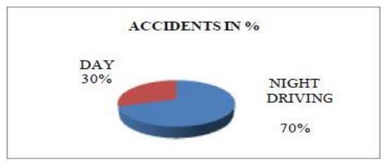
Thenumberofvehiclesontheroadisrapidlyrising,as isthenumberoftrafficaccidentsaswecanseeinFigure1. The majority vehicle accidents, especially at night, are caused by blinding headlights. While diving at night, the headlight beam of incoming vehicles immediately impacts the driver's eye, causing blurry vision that takes 3 to 8 seconds to recover. If the car's speed is 70 km/h at the moment,itwillgoofftheroadorcollidewithanincoming vehicle.[9]
Toaddresstheissuesraisedinbothpapers(refs.3and 4), we created a new circuit that operates the headlight beamdirectly.Somecomponentsmustbeadded,aswellas wiringalterations.Inbothpapers,atypicalproblemoccurs while driving in cities, where street lights or store lights damage the system and shorten the life of the relay and
International Research Journal of Engineering and Technology (IRJET) e ISSN: 2395 0056
Volume: 09 Issue: 05 | May 2022 www.irjet.net p ISSN: 2395 0072
headlight. The manual mode, which is already available in thecar,isemployedtolessenthis.Inmodernpractice,the dipper beam is controlled manually by a switch mounted on the steering column. Most drivers do not employ manual dipper control for a variety of reasons, including thefactthatthedippercontrolswitchisusedhundredsof timesduringnightdriving.Anotherexplanationisthatthe driver would rather focus on the steering wheel than dip theheadlightbeam.Anotherbigfactorisego,whichcauses oneindividualtowaitfortheothertostartdipping,which mayormaynothappen.
A CAN bus is a LAN (Local Area Network) controller. TheCAN bus can transportserial data oneat a time. For transmitting and receiving data, all participants in the CAN bus subsystems are available via the control unit on the CAN bus interface. The CAN bus is a multi channelcommunicationsystem.Whenoneunitfails,ithas no effect on the others. The data transfer rate of the CAN bus in a vehicle system varies. The high speed real time controlfashionrangesfrom125Kbpsto1Mbps.Whilethe low speed transmission rate ranges from 10 to 125K bps. Others,suchasmultimediasystems,operateatamedium speed pace in between the previous two. This method distinguishesdistinctchannelsandimprovestransmission efficiency.
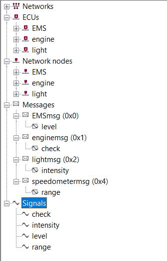
The Vector CAN tools only read access communication relevant data, which is defined, changed, and maintained exclusively inside CANdb++.SothattheVectorMaytoolscanaccess the communication relevant data, it must exist in theformofCANdbnetworkfiles.
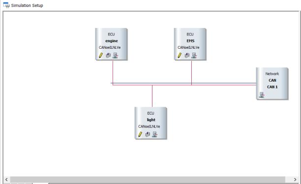
We're making four message signals here: EMS (Engine Management System), Engine, and Light.Eachmessagesignalisallocatedtoacertain systemtoconnectwith.
CANoe is used at the start of the development processforanECUorECUtoconstructsimulation models that emulate the behavior of the ECUs. These models will be used as a foundation for analysis, testing, and integration of bus systems and ECUs throughout the lifecycle of ECU development.Datacanbedisplayedandanalyzed ineitherraworsymbolicform.
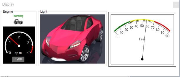
With the Panel Editor, you may design visual panels on which the user can adjust the values of discreteandcontinuousenvironmentvariables,as well as display signals, interactively throughout the simulation. Figure 5 depicts the design system's Instrument Cluster panel, whereas Figure 4 depicts the simulation sensors. The Instrument Cluster, in particular, shows some Running status, light signals, automobile speed, engine speed, and Fuel detection. The simulation
International Research Journal of Engineering and Technology (IRJET) e ISSN: 2395 0056
Volume: 09 Issue: 05 | May 2022 www.irjet.net p ISSN: 2395 0072
sensor panel primarily delivers signal values for CarSpeedandEngineSpeedtothebustoreplace realnodesthataresimpletooperate.
Fig 4: Displaypanel
Upper beam covers a bigger extent of up to 70 meters, while dipper beam covers a smaller distance of up to 25 meters, and the intensity of head light is varied at both times.Figure8showshowmuchdistanceiscoveredbythe topandlowerbeamsofaheadlight.
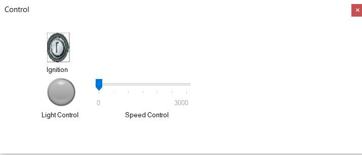
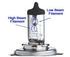
Fig 5: Controlpanel

We may use the tracing window to monitor the data from the bus and see if there is an incorrect frame. Wemayalsoseeanddetermineifthedata being sent and received is correct. This can aid development engineers in debugging and modifying the application, as well as improving development efficiency. Figure 6 depicts several dataframesusedwhiledebugging.
Fig -6: CANmessagesindifferentnodes
Figure 7 shows a headlight vehicle with a double filament bulb. One filament is used for the top beam and anotherisutilizedforthelowerbeam.Theheadlightisthe only source of visibility while driving at night, and it is required generally from evening 6.00pm until morning 6.00am.Thedrivermaymanuallyaltertheheadlampfrom uppertolowerbeamorviceversa.
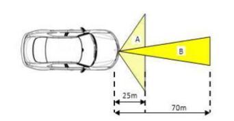
Fig 8: HeadlightofVehicle
Because there are fewer circuit components in this system,thecircuitbreadboarddesignisnotascrucial.The breadboard is used to implement the circuit as shown in the diagram. For the design and implementation of the components depicted in fig.4, the most readily accessible andcorrectcomponentsareemployed.
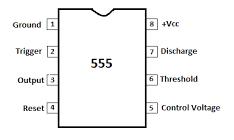
Thefundamentalcontrolofthissystemisthe555 timer IC, which is well recognized for producing consistent time delays. The timing logic for this system is developed in monostable mode. It is a dual in package 8 pin integrated circuit (DIP). Figure9depictsthe555IC'spindiagram.
2022, IRJET | Impact Factor value: 7.529 | ISO 9001:2008 Certified Journal |
International Research Journal of Engineering and Technology (IRJET) e ISSN: 2395 0056
Volume: 09 Issue: 05 | May 2022 www.irjet.net p ISSN: 2395 0072
controltomovefromuppertodipper.Whentheoncoming car passes, the LDR becomes black and the output of the 555ICchanges.Itswitchestheheadlightbeamfromdipper tohigher.
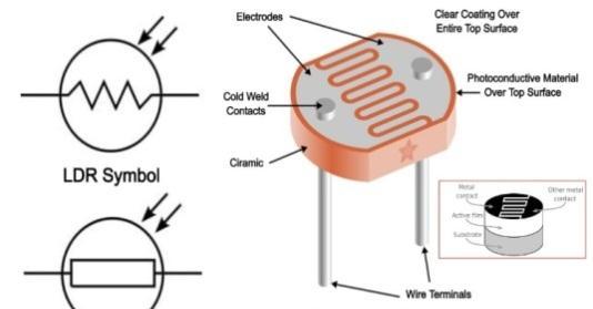
Inthissetup,theLDRservesasasensor,detecting the incoming vehicle's headlight beam. The LDR constructionschematicisshowninFig.10.
Fig 10: LDRSensor
This system operates on a 12V supply that is drawn straight from the car battery, which is already present in each vehicle. It offers a steady DC supply, and the system may be securely powered by the vehicle's battery without the use ofanyextracomponents
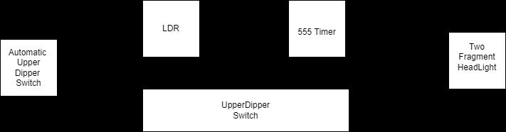
The block diagram in fig.11 illustrates the dipper control system clearly. LDR detects approaching car headlights in automated mode, as the resistance of LDR varieswithlightintensity.Thevoltagesuppliedtothe555 timer control IC changes as the intensity changes. The output changes its status to high or low according on the trigger and threshold conditions, causing the headlight
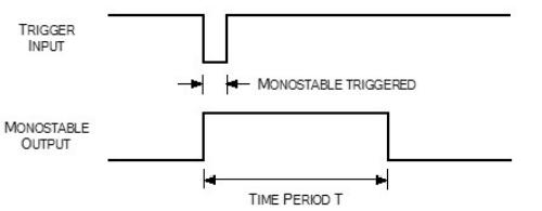
The monostable mode of the 555 timer application is usedinthissystem.Figure12depictstheoutputwaveform of the monostable mode, which provides the time delay T whenalowinputpulseissuppliedtothe555IC.
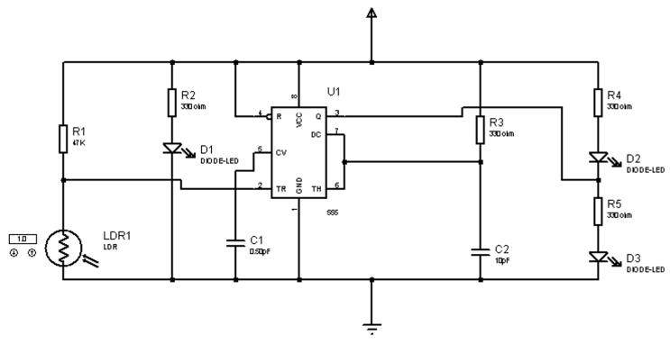
A 555 Timer IC is used in this circuit as shown in Fig 13.Whenthevoltageatpinnumber2islessthanone3rd ofthesuppliedVCC,thetimerICwilloutputatpinnumber 3. The circuit employs three LEDs: an indication LED, an upper light LED, and a dipper light LED. In the circuit, thereisanLDRthatprovidesvariableresistancebasedon the intensity of the light shining on it. When the circuit first turns on, the upper light will shine and the dipper light will remain off. However, when light from an oncoming vehicle strikes LDR, the resistance reduces. Becauseofthisdecreasein resistance,thevoltageapplied totimerICpinnumber2willbelessthanone thirdofthe givenVCC.Asaresult,thetimerICisactivated,andweget ahighoutputvoltageatpinnumber3.Thisoutputwill be linked to the dipper LED, causing it to shine while also turningouttheupperLED.Whennolightislandingonthe LDR,itsresistanceincreases,causingthetimerIC'soutput to be low. As a result, the upper LED will once again illuminatewhilethedipperLEDwillswitchoff.
International Research Journal of Engineering and Technology (IRJET) e ISSN: 2395 0056
Volume: 09 Issue: 05 | May 2022 www.irjet.net p ISSN: 2395 0072
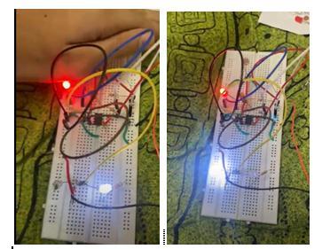
The circuit is created on the breadboard according to the circuit schematic, and a 12V power source is used to powerit.LDRresistanceishighinthedark(20k)andlow in the light (2 k). Allow the little torch light to fall on the LDRandmeasureitsresistance.Wealtertheresistanceof the LDR with a little flame and measure some distance at differentresistances.
node of this system as well as the overall system coordinationtest.
The automatic dipper improves nighttime safety, allowing drivers to drive pleasantly and safely to their destination.Therearetwomodesavailable:automaticand manual. When travelling in cities, there are lights everywhere, which might interfere with the device's operation; at that point, the mode can be switched to manualmodetoeliminateheadlightflickering.Whenboth cars were outfitted with the "Automatic Dipper," they efficiently dipped each other's headlight beams. The main components required to run the circuit are readily accessibleandreasonablypriced.Thecircuitiscompatible withanycaranddoesnotrequireanyadditionalpower;it mayoperateefficientlyonthevehicle'sbattery.Asaresult, the installation of this safety system in each car provides safety while driving at night, increases the driver's comfort level, and reduces the risk of an accident road trafficcollisions
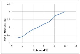
Asaresult,theprecedinggraphshowsthatLDRresistance ishighindarknessandlowinlight.Asaresult,thedipper controlisaffectedbylightintensityanddistance.
[1] Zhou, F., Li, S., & Hou, X. (2008, June). Development method of simulation and test system for vehicle body CAN bus based on CANoe. In2008 7th World Congress on Intelligent Control and Automation(pp. 7515 7519).IEEE.
[2] WuKuanming.TheTheoryandDesignofApplication System of CANBus. Beijing: Beijing University of AeronauticsandAstronauticsPress,2001.18 34
[3] Vector Informatik GmbH. CANoe Manual (Version 5.2).2005
[4] YangLi,YanWeisheng,GaoJian,ZhangLichuan.CAN System
[5] Development Based on CANoe Measurement and ControlTechnology,2007,26(4):66 67,75
[6] Zhang Xinbo, Sun Zechang, Luo Feng. Study on CAN BodyNetwork
This article describes the simulation and testing system development process for the Car Dashboard CAN bus. Using the system development and analysis tool CANoe, we establish the simulation and test environment in which we complete the simulation and testing for each
[7] Simulation with CANoe. Journal of Jiangsu University (Natural Science Edition), 2003, 24(5): 36 39K. Elissa, “Title of paper if known,” unpublished. R. Nicole, “Title of paper with only first word capitalized,”J.NameStand.Abbrev.,inpress.
[8] Y.Yorozu,M.Hirano,K.Oka,andY.Tagawa,“Electron spectroscopy studies on magneto optical media and plastic substrate interface,” IEEE Transl. J. Magn. Japan, vol. 2, pp. 740 741, August 1987 [Digests 9th AnnualConf.MagneticsJapan,p.301,1982].
International Research Journal of Engineering and Technology (IRJET) e ISSN: 2395 0056
Volume: 09 Issue: 05 | May 2022 www.irjet.net p ISSN: 2395 0072
[9] M. Young, The Technical Writer’s Handbook. Mill Valley,CA:UniversityScience,1989.
[10] Narkar, T. V. (2016). Automatic dipper light control for vehicles International Journal of Research in EngineeringandTechnology,5(3),97 101.
[11] Ramakant Gayakwad, “Op Amps & Linear Integrated Circuits”, 4th ed. PHI Learning Private Limited, New Delhi,pp.400 405.
[12] Roy Choudhary, “Linear Integrated Circuits”, 4th ed. NewAgeInternationalPublishers,pp.311 315.
[13] Sushil Kumar Choudhary, “Electronic Head Lamp Glare Management System for Automobile Applications”, International Journal of Research in Advent Technology, Vol.2, No.5, May 2014, pp. 402 416.
[14] Muralikrishnan.R, “Automatic Headlight Dimmer A Prototype for Vehicles”, International Journal of ResearchinEngineeringandTechnology,Vol.3,Issue: 02,Feb 2014,pp.85 90.
[15] Snehal G. Magar , DzAdaptive Front Light Systems of Vehicle for Road Safetydz ʹͲͲ5 International Conference on Computing CommunicatioControl and Automation,pp.551 554(IEEE2015).
[16] Ms. Priyanka Dubal, Mr. Nanaware J.D, DzDesign of Adaptive Headlights for Automobilesdz International Journal on Recent and Innovation Trends in Computing and Communication, Volume: 3 Issue: 3, pp1599 1603,March2015.
[17] Ms. Monal Giradkar, Dr. Milind Khanapurkar, DzDesign & Implementation of Adaptive Front Light SystemofVehicleUsingFPGABasedLINControllerdz 2014 Fourth International Conference on Emerging TrendsinEngineering&Technology(IEEE2014).
[18] Mr. Prateek Khurana, Mr. Rajat Arora, Mr.Manoj Kr. Khurana DzImplementation of Electronic Stability Control and Adaptive Front Lighting System for AutomobilesdzIEEE2014.
[19] ShreyasS, Kirthanaa Raghuraman,PadmavathyAP,S Arun Prasad, G.Devaradjane, DzAdaptive Headlight SystemforAccidentPreventiondz2014International Conference on Recent Trends in Information Technology(IEEE2014
[20] Gao Zhenhai, Li Yang, DzControl Algorithm of Adaptive Front lighting System Based on Driver PreviewBehaviordzͲndInternationalConferenceon
Measurement, Information and Control (IEEE 2013), pp1389 1392.
[21] Yali Guo, Qinmu Wu, Honglei Wang, DzDesign And Implementation Of Intelligent Headlamps Control System Based On CAN Busdz International ConferenceonSystemsandInformatics(ICSAI2012) (IEEE2012),pp385 388
2022, IRJET | Impact Factor value: 7.529 | ISO 9001:2008 Certified Journal |