International Research Journal of Engineering and Technology (IRJET) e ISSN: 2395 0056

Volume: 09 Issue: 05 | May 2022 www.irjet.net p ISSN: 2395 0072
International Research Journal of Engineering and Technology (IRJET) e ISSN: 2395 0056
Volume: 09 Issue: 05 | May 2022 www.irjet.net p ISSN: 2395 0072
1,3
Abstract In any machining center the spindle forms a vital component as it holds and rotates the cutting tool. As such, the modelling and analysis of this part of the machining center is crucial for successful design and subsequently manufacturing them. The dimensional accuracy and surface finish of the work piece in machining operation are of particular interest and the way the machine tool spindle influences these parameters is of great concern to the user. In the present work, the static and dynamic behavior of horizontal CNC machining center spindle is studied. The spindle is modelled in ANSYS and is analyzed for static and dynamic loading. The deflection curves and mode shapes are obtained at different cutting forces for EN24 and H13 materials.
Key Words: Machining center, dynamic behavior
Thestateofartcomputernumericalcontrol(CNC)machine tool needs higher speed, higher precision, and good efficiency,thehigh speedmotorizedspindlehasbecomethe most important part of metal cutting machine tool. High speed motorized spindle influences the overall technical performance of the machine tools, [1,2]. Hence it is importanttoanalyzethedynamiccharacteristicsofspindle. Bearings carry a great significance as quality, accuracy of machinedependsonthem.Theoperatinghistoryofspindle Operating speed, Type of lubrication, Estimating the workloads,Torque,Spindlematerialmustknowparameters. Spindlesaremostlyhollowandcontainsthedrawbarwhich decreases its weight. To maintain the accuracy under the influence of cutting forces and the moving weight of the machinetoolelements,thespindlestructureshouldpossess high static and dynamic stiffness, this is to ensure it withstandsvariousforcesactingonit[3].Al Shareefetal.[4] suggestedaquasi staticmethodofanalyzingmachinetool spindles. They worked by taking the amplitude of the dynamic forces and applies them to a static model of the spindle bearingsystem.
WangandChang[5]analyzedaspindle bearingsystemwith afinite elementmodelandcomparedwith theresultof theirexperimentwhichhad Radialandtiltingspringsand dashpots in angular contact spindle ball bearings. Their analysis showed a significant effect on higher order vibrationmodes.ZhaoHaitaoet.al.[6]suggested amethod forcomputingthecoefficientofconvectionheattransferof thespindlesurfacebyreferencingthetheoryoncomputing
***
thecoefficientofconvectionheattransferofaflatplatewhen airflowsalongit.YuzhongCaoandAltintas[7] integrated themodelofthespindlebearingandmachinetoolsystem, which consists of a rotating shaft, tool holder, angular contact ball bearings, housing, and the machine tool mounting. Chi Wei Lin. et al. [8] proposed a model with experimentalvalidationandsensitivityanalysisforstudying various thermo mechanical dynamic spindle behaviors at highspeeds.Spindleisusuallymadeofcase hardenedNi Cr steel and their configurations depend on how it holds the cuttingtools,thefitofdriveelementandtypeofitsbearings. Theyaremadehollowtocontaindrawbaranddecreasethe spindleweight.High SpeedMachining(HSM)iswidelyused in the manufacturing industry. The premature failure without alarming signs leads the development of spindle technology to be strategically critical for the HSM implementation.
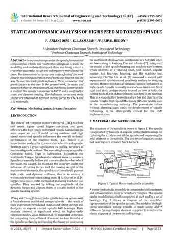
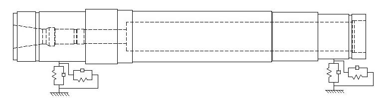
ThestructureofthespindleisshowninFigure1.Thespindle issupportedbytwosetsofangularcontactballbearingsfor reducingtheaxialrunoutofthespindleandimprovingthe axialstiffnessofthespindle.Thetwosetsofangularcontact ballbearingsareinstalledback to back
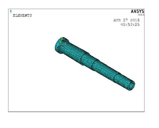
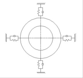
Amotorizedspindleassemblyiscomposedofdifferentparts andsubassemblies,manyofwhicharecomplex.Thespindle canbemodelledasashaft,supportedateachendbyasetof bearings. Fig. 2 shows a diagram of the simplified representationofthespindlesystem.Themodelofthehigh speed motorized milling spindle is made using ANSYS software.Spring damperelementisappliedtosimulatethe elasticsupportofthetwosetsofbearings
International Research Journal of Engineering and Technology (IRJET) e ISSN: 2395 0056
Volume: 09 Issue: 05 | May 2022 www.irjet.net p ISSN: 2395 0072
condition,thebendingstiffnessismoreimportantthanaxial stiffness. The bending stiffness (K) of the spindle unit is definedasfollows:ifthefrontpartofthespindlegenerates unitradialdisplacement δ,andtheforceinthedirectionof thedisplacementis Fr :
Figure2.Equivalentdynamicmodelofaspindle.
K = Fr/δ (N/μm)
Inthestudyofthestaticloadanalysisofspindle,therotating speed loading analysis is done at first, and the maximum rotating speed of the motorized spindle is greater than or equalto12000rpm.Themaximumdeformationisonly3.67 micron,whichbasicallydoesnotaffecttheprecisionofthe spindle
Figure3.Layoutofspringdamperunit.
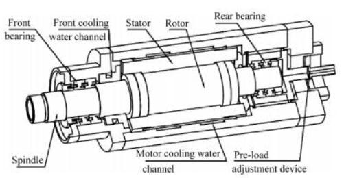
COMBIN14elementwhichcanbeappliedtosimulatesprings and dampers is provided by ANSYS. The Solid 92 element which is a tetrahedral element with ten nodes is used to simulatespindlepart.Thefiniteelementmodelofspindleis showninFig.4Thetotalnumbersofnodesandelementsare 17303and 9533 respectively. The material used for the spindleareEN24andH13.WhenassignedmaterialisEN24 tothemodelinANSYS,theweightofthespindleis20.523kg. and for that of H13 is 18.349 kg. The bearing used are XCB7017C.T.P4SandXCB7018C.T.P4S.Thespringstiffnessof eachsetofbearingsis310.3N/μmand274.3N/μm.Sincethe damperhaslittleinfluenceonthenaturalfrequencyofthe transversalvibrations,thedamperelementcanbeignored.
During milling, the vibration cannot be avoided, and this changes the relative position of work pieces and milling cutters and also accelerates the wears of milling cutter. Therefore, the Modal analysis of spindle is the primary problemofdynamiccharacteristicsanalysis.
ModalanalysisisbasisofHarmonicresponseanalysis.The computing time is effectively reduced based on the completed modal analysis. For harmonic response, the cutting force is applied on the end of the spindle taper to analyzethe10orderfrequency,whoserangeisfrom0Hzto 1400Hz with step 400Hz. Analysis is done by selecting a nodefromtheconepartofspindle
Radialstiffnessofangularcontactballbearings Kr=1.77236Km(Z2Dw)1/3cos2/sin1/3(fao)1/3 N/M
Bendingstiffness(K)=fr/δ δ=radialdisplacement. fr=forcerequiredtobeimposedinthedirectionof displacement.
CuttingSpeed(m/min) Vc =
Thespindlestiffnessiscloselyrelatedwiththeloadcapacity andvibrationresistance,whichisanimportantperformance indexofthemotorizedspindle.Thespindlestiffnessincludes the axial and bending stiffness. In normal operating
SpindleSpeed(rev/min) η=
FeedSpeed Vf =fz*n*zn
Feedperrevolution fz =
Feedpertooth fz =
2022, IRJET | Impact Factor value: 7.529 | ISO 9001:2008 Certified Journal |
International Research Journal of Engineering and Technology (IRJET) e ISSN: 2395 0056
Removalrate(cm3) Q= SpecificCuttingforce(N/mm2) Kc =KC1*ηm mc
Averagechipthickness (if ae/Dc ≤0.1) hm=fz (ifae/De ≥0.1) hm =
NetPower Kw =
ForworkpiecematerialALUMINIUM
Cuttingparameters1 Feed fz=0.4mm ae =0.2 Cutterdiameter Dc =150mm ae =30mm ap =100mm Entryangle Kr =450 No.of Inserts Z=8
Averagechipthickness hm = = = =16.123
Specificcuttingforce Kc =960N/mm2
For the workpiece material Al, with cutting parameters P1,belowaretherotationalspeedandcuttingforceanalysis results.
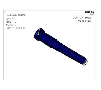
Fig5 DeflectionofspindleforEn24
Fig5showsthespindledeflectionundertherotationalspeed analysis and cutting force analysis where the deflection is 0.016mmand0.005mmrespectively.
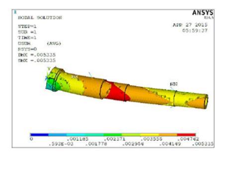
Fig6Delectionofspindleundercuttingforce
Fig7showsthespindledeflectionundertherotationalspeed analysis and cutting force analysis where the deflection is 0.016mmand0.005mmrespectively.
For the same Aluminium material and with cutting parameters P1 , the table below shows the natural frequenciesofthespindleanditsmodeshapes.
Table :1 Natural frequencies of spindle 1 0 2 0 3 556.28 4 1143.5 5 1321.2 6 1553.5 7 1564.3 8 2124.8 9 2326 10 2754.1
Volume: 09 Issue: 05 | May 2022 www.irjet.net p ISSN: 2395 0072 © 2022, IRJET | Impact Factor value: 7.529 | ISO 9001:2008 Certified Journal
International Research Journal of Engineering and Technology (IRJET) e ISSN: 2395 0056
Volume: 09 Issue: 05 | May 2022 www.irjet.net p ISSN: 2395 0072
Fig7 3rd ModeShapeofthespindle
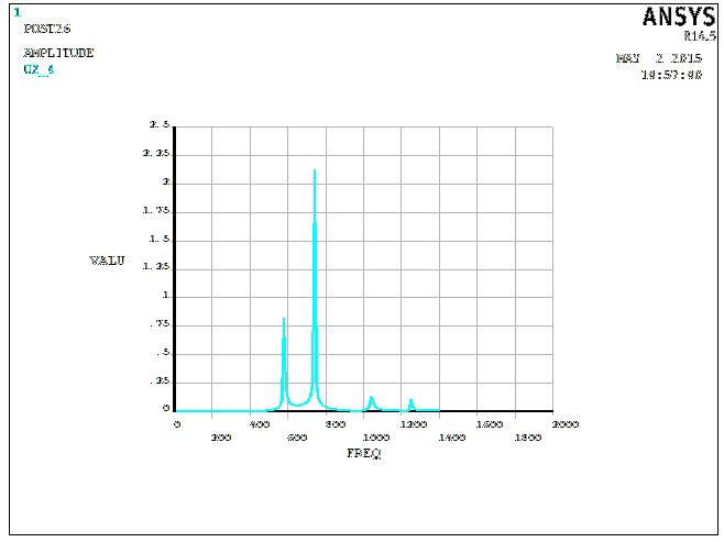
Fig10:Frequencyresponseunderexternalloading
Figure9and 10showsthefrequencyresponseanalysis andthepeakamplitudeofvibrationatnode7and2 respectively
4.2 Spindle MATERIAL: H13
For the workpiece material Al, with cutting parameters P1,belowaretherotationalspeedandcuttingforceanalysis results
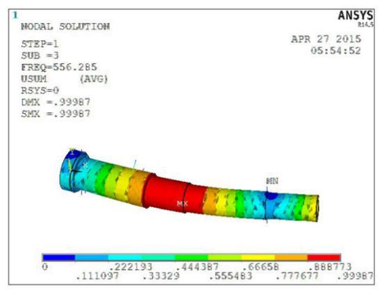
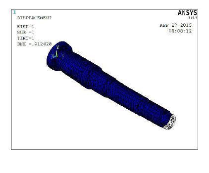
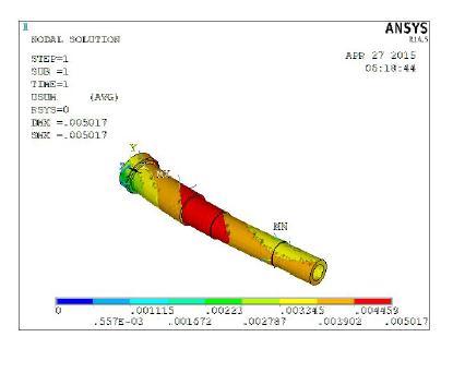
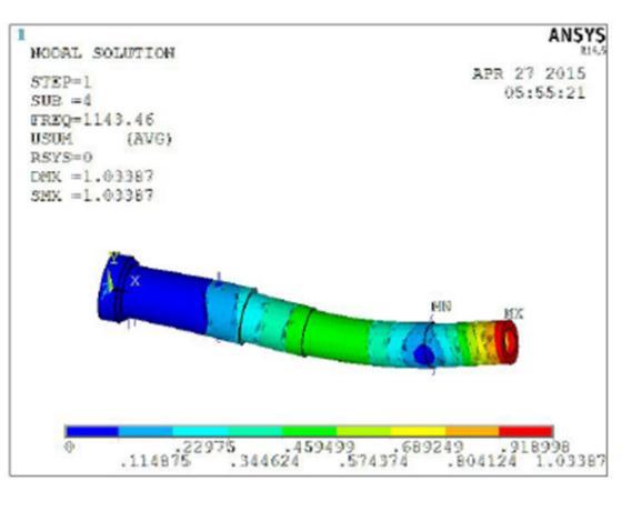
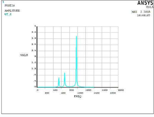
Fig8:4th ModeShapeofthespindle
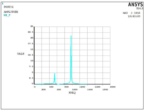
Figure7andfig8showsthemodeshapesofthespindlewith materialEN24.3rdmodeshapeand4thshapeareshownwith natural frequency at that mode of vibration is 556.28 and 1143.5respectively.Of10modeshapes,3rd and4th shapes areillustrated
The harmonic Analysis is performed on the spindle by applying Radial Force = 2305N at Frequency Range 0 1400HzwithSubsteps140
Fig10Deflectionofspindleunderrotationalspeed
Fig9:Frequencyresponseunderexternalloading
Fig11Deflectionofspindleundercuttingforce
2022, IRJET | Impact Factor value: 7.529 | ISO 9001:2008 Certified Journal
International Research Journal of Engineering and Technology (IRJET) e ISSN: 2395 0056
Fig 10 and fig 11 shows the spindle deflection under the rotationalspeedanalysisandcuttingforceanalysiswhere thedeflectionis0.0124mmmmand0.005mmrespectively
For the same Aluminum material and with cutting parameters P1 , the table below shows the natural frequenciesofthespindleanditsmodeshapes
Table 2 : Natural Frequency values
1 2 3 4 5 6 7 8 9 10
0 0 60 2. 5
123 7.9 14 14. 4
1675 .9 167 6.8 23 38 25 14 .8
The harmonic analysis is performed on the spindle by applying Radial Force = 2305N at Frequency Range 0 1400HzwithnumberofSubsteps140
297 5
The above table is the listing of the first 10 natural frequenciesofthespindleundertheactionoffreevibration.
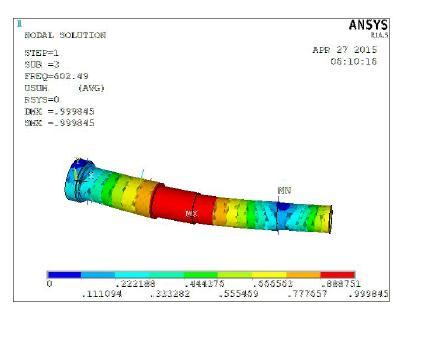
Fig113rd ModeshapeofthespindlewithH13material
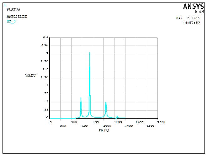
Fig12Frequencyresponseunderexternalloading
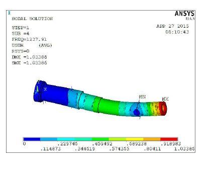
Fig114 th ModeshapesofthespindlewithH13material
Figure 7 shows the mode shapes of the spindle with materialH13.outof103rdmodeshapeand4thshapeare shownwithnaturalfrequencyatthatmodeofvibrationis 602.5Hzand1237.9respectively
Fig13Frequencyresponseunderexternalloading
Figure12and13showsthefrequencyresponseanalysisand the peak amplitude of vibration is shown at node 7 and 2 respectively
1. The static analysis, the modal analysis and harmonicresponseformotorizedmillingspindleis donebymeansofANSYS.Themethodtoestablish thefiniteelementmodelofthebearingsupportby spring damper element COMBIN 14 was investigatedandtested.
2. Theaboveanalysisareperformedontwodifferent materialstooptimizethedesign.Itwasfoundthat thedeflectionof H13waslesserthan thatofEN24.
Volume: 09 Issue: 05 | May 2022 www.irjet.net p ISSN: 2395 0072 © 2022, IRJET | Impact Factor value: 7.529 | ISO 9001:2008 Certified Journal | Page3577
International Research Journal of Engineering and Technology (IRJET) e ISSN: 2395 0056
Volume: 09 Issue: 05 | May 2022 www.irjet.net p ISSN: 2395 0072
3. The modal analysis was performed on both the material combinations and the first natural frequency of H13 was slightly higher when comparedtoEN24.
4. TheamplitudeofvibrationinEN24wasmorethatif H13inharmonicanalysisHenceEN24issubjected tomorevibration.
1. Machine Tool Design By N. Acherkan,Isbn 10: 0898750474,UnivPrOfThePacific,(April2000)
2. DesignAndConstructionOfMachineToolsBy H.C. Town,IliffeBooks,1971
3. CentralMachineToolInstituteHandBookBy CMTI Bangalore
4. Al Shareef,K.J.H,Brandon,J.A.,"OntheApplicability of Modal and Response Representations in the Dynamic
5. Wang, W. R., Chang, C. N., Dynamic analysis and design of a machine tool spindle bearing system, Journalof VibrationandAcoustics,TransactionsoftheASME (ISSN1048 9002),vol.116,no.3,p.280 285.
6. ZhaoHaitao,YangJianguo,ShenJinhua,Simulation of thermal behavior of a CNC machine tool spindle,InternationalJournalofMachineToolsand Manufacture,Volume47,Issue6,May2007,Pages 1003 1010.
7. Yuzhong Cao Y. Altintas, Modeling of spindle bearing and machine tool systems for virtual simulation of milling operations, International JournalofMachineToolsandManufacture,Volume 47,Issue9,July2007,Pages1342 1350.
8. Chi WeiLin,JayF.Tu,JoeKamman,Anintegrated thermo mechanical dynamicmodeltocharacterize motorizedmachinetoolspindlesduringveryhigh speed rotation, International Journal of Machine ToolsandManufacture,Volume43,Issue10,August 2003,Pages1035 1050.
9. Z. C. Lin, and J. S. Chang, “The building of spindle thermal displacement model of high speed machinecenter”, Int. J. Adv.Manuf. Technol.,vol.34, pp.556 566,Sept.2007.
2022, IRJET | Impact Factor value: 7.529 | ISO 9001:2008 Certified Journal