2UG Scholar, Dept of ECE, Sreenidhi Institute of Science and Technology, HYD.
Volume: 09 Issue: 03 | Mar 2022 www.irjet.net p-ISSN: 2395-0072 © 2022, IRJET | Impact Factor value: 7.529 | ISO 9001:2008
Dr.S N Chandra Shekhar1 , Tankashala. Komal2 , VVVSSV. Nithin Reddy3 , Vangala. Sneha4
Abstract: ThisUnachievableEnergymeterisdesignedtopreventreadingsfrombeingtamperedwith.Theideagivenhereisto useawirelessmonitoringdevicelinkedtoasmartphonetodisplaytheamountofenergyspent.Thecommunicationsystemis builtwithIoTandmaybeconnectedtoadigitalenergymeterviaanMCUprocessor.Thedigitalenergymeter,whichismade up of digital components, must be mounted above the electric pole itself, out of reach of the energy user. Consumed energy data can be tracked using a smart phone, avoiding the installation of an energy meter on the energy user's campus and eliminatingthepossibilityofmetertampering.
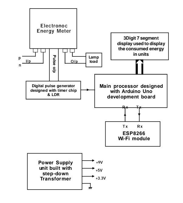
The main unit of the energy meter can be mounted over the electric pole itself, preventing meter manipulation because the mainunitisnotaccessibletoenergyusers;instead,theycanchecktheirenergyusagestatisticsusingIOTtechnologyontheir mobile phone. To show the theory in practice, we simply needed one electronic energy meter. This energy meter, which is mounted on the pole, must be updated so that the data on energy usage may be transmitted via Wi Fi moduleThe meter generatesandtransmitsproportionatepulsesbased ontheenergyusage.Toimproveenergymeteraccuracy,itisdesignedto create 1600 pulses per unit consumption, with the length between the two pulses varying depending on the load The pulse ratewillincreaseiftheburdenistooheavy.Thedatafromthemeter'spulseoutputisnowprocessedbytheArduinoMCUand delivered.BecausetheIOTislinkedtoasmartphone,thereceivedenergyconsumptiondatawillbeshownonthesmartphone. Theutilizedenergydataisshownona7 segmentdisplaythatisinterfacedwithapoleunitsothatitmaybereadfromground levelbyenergyusersorbillcollectors.
Theelectronicenergymeter(EEM)wasemployedintheprojectwork,andithasalotofcharacteristics.Thekeycharacteristic isthatitgeneratespulsesbasedontheamountofpowerconsumed.Theconsumedenergyistranslatedtodigitalandshown ona7 segmentdisplaybasedonthisdata.BecausetheEEMhassomanybeneficialfeatures,itcanbeadaptedtodoavariety oftasks,makingitasmartenergymeter.Smartenergymetersaregainingpopularityasaresultofthewiderangeoffeatures theyprovide.
TheconceptisnovelinthatitusesIoTtechnologytobroadcastenergyconsumptioninformationtotheconcernedcellphone.
The main goal of this project is to create an unachievable smart energy meter that can be mounted on an electric pole. The meter'spulsewill beanalogue,butthemicrocontroller basedArduino processorusedheretodothecomputingprocesswill nottakeanaloguepulses,sotheanaloguepulseistransformedtoadigitalpulseusingapulseconverter.
4UG Scholar, Dept. of ECE, Sreenidhi Institute of Science and Technology, HYD.
International Research Journal of Engineering and Technology (IRJET) e ISSN: 2395 0056

Though this kind of system does not present in our country, the benefits and applications of this system are numerous, as discussed in the next chapter. When it comes to smart energy meters, the potential for smart meters to provide consumers
1. INTRODUCTION
1B.E, M.Tech, PHD, Dept of ECE, Sreenidhi Institute of Science and Technology, HYD.
IOT BASED UNATTAINED TAMPER PROOF DIGITAL ENERGY METER
Certified Journal | Page576
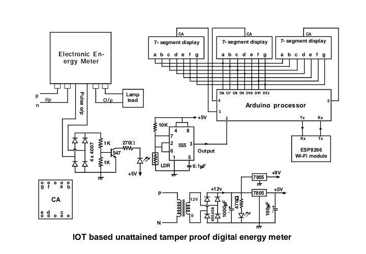
The concept provided in this project work will be tested in practice using an electronic energy meter, which is designed to createpulsesinresponsetotheloadsuppliedtoit.Theenergymeter'spulseoutputisconvertedtodigitalandsuppliedtothe ArduinoUno board. Consumed energy informationcanbe presentedusinga 3digit7segmentdisplayunit thatisinterfaced with Arduino. Because this system is intended to be put on an electric pole, the 7 segment display is designed to be viewed fromadistance,whichinturnallowsthemetertoadjustitself.
***
The project work specifics provided in this paper are centered on new developments in smart energy metering technology, whichaimstoavoidtheinstallationofanenergymeterinanenergyusercompound,thereforepreservingenergyfrombeing theft by tampering the meter. Although smart energy meters offer a wide range of benefits, this project effort is focused on displayingmeterreadingsviaanenergyconsumer'ssmartphoneutilizingIOTtechnology.
3UG Scholar, Dept. of ECE, Sreenidhi Institute of Science and Technology, HYD.
with improved information and control over their energy use, resulting in both financial savings and energy consumption control, has been debated for years. All state electricity agencies are encouraged to seek new technology to expand their benefits and find cost efficient solutions. As an engineering student, I hope to serve my country and provide an appropriate solutiontothecurrentproblem.
The IC starts generating pulses through pins 23 and 24 based on the voltage and current samples given to pins 8 and 6, respectively, and with the help of a predetermined frequency. Because this chip can create impulses, a two phase stepper motor can be used to drive the mechanical counter, allowing the meter reading to be displayed. Because the purpose is to display the pulse rate in digital format, the impulse is translated to digital using a timer devicesettomonostableoperation.Thepulserateisjusta measurement from a meter that displays consumption in Pulsesunits.aregeneratedthroughpulseoutputpinsdepending on the load supplied to the meter; as the load increases, short duration pulses are generated, implying that more pulses are generated in less time. Longer duration pulses willbecreatediftheloadislower.
Page
The Internet of Things (IoT) is a communication network in which physical things are linked to one another or to bigger systems.Thisnetworkcapturesbillionsofdatapointsfromavarietyofgadgetsthatweuseonadailybasisandconvertsthem into meaningful information. There are around 20 billion gadgets that interact with each other in the globe now, with estimatesof75 billion devicesby2025.Thisdemonstratesthatwe will be livingin citieswithIoT inthecomingyear.It will evolve into smart cities that can keep up with today's fast paced and planned lifestyles. This transformation will provide us withnumerousopportunitytosimplifyourlives.
Volume: 09 Issue: 03 | Mar 2022 www.irjet.net p-ISSN: 2395-0072 © 2022, IRJET | Impact Factor value: 7.529 | ISO 9001:2008 Certified Journal | 577
Accordingtowatthourmeterregulations,whenaconstant load of 1000W is supplied to the meter output terminals for one hour, the meter should reflect one unit of power consumption. This meter reading standard has been followed for the past five decades, whether it is an electromechanical meter or the most recent Smart digital energymeter,becauseitisaninternationalstandard.
2.2. Current Sensor
2.3. Digital energy meter with a digital display :
Thisinnovativeconceptis intended to raise our state's power department'sattentiontoit. The 4RTHchapter containsa full circuitdescriptionoftheproject'swork.Beforegoingintothedetails,it'simportanttoknowtheimportanceofIoTtechnology.
International Research Journal of Engineering and Technology (IRJET) e ISSN: 2395 0056
Dependingonthecurrentflowing,onlyasmallamountof voltage is dropped across the Tin conductor, which is slightly greater than copper conductor. The thickness of the conductor has an effect on the voltage drop across it. According to the data available on the internet, a conductor with a thickness of one mm, a width of five millimeters,andalengthofthirtymillimetersisutilized.At one amp load, it is projected that about 0.1 volt will drop across the wire based on these dimensions and the descriptionaccessible on websites.220 wattsare equal to oneampload.
IoTtechnologyallowsforinformationsharingamongstvarioussmartdevicesfromanywhereintheworld.Inthisclimate,this technologyhasthepotentialtoacceleratesmartenergymeterresearch.
The MCP3909 chip is a popular device that is commonly usedinsinglephaseenergymeters.Itisa24pinchipthat is designed to be surface mounted. This chip's internal structure allows it to meet the requirements of international metering standards. Even though the chip has a lot of features, only a few of them are used to construct a simple electronic energy meter. The analogue input data collected from voltage and current samples circuits will be transformed to digital for further processing because this chip has a 16 bit ADC internal. A constant frequency of 3.579 MHz will be generated with the help of a crystal attached externally to pins 17&18 to executeinternalfunctionsproperly.
2.1 Pulse rate
2. DESCRIPTION
The notion of digitally displaying consumed energy provided here cannot be verified without the use of an energy meter. As a result, the energy meter plays a significantroleinthisproject,anddefiningitsoperationis
This is a well known fact in the field of electrical instrumentation. In most circumstances, current transformers (CTs) are employed, but one Tin metal strip/plateisusedasacurrentsensorinthisproject.Very little voltage will be dropped across this conductor, dependingonthecurrentrunningthroughit,anditwillbe measured.Becausethisstripmustbelinkedinserieswith theload,itshouldbeattachedbetweentheenergymeter's inputandoutputpowerterminals.
2) Microcontroller 3) Displaysection 4) Latchcumdisplaydriver
EnergyMeteringICfunction
TheArduinounit'smajorfunctionsarelistedbelow,andit isprogrammedappropriately.
Tousea seven segment displaytoshowtheamount of energyutilizedinunits.
1.To obtaindata on energy usefromthe energymetering 2.IC.
1) DigitalPulseGenerator
3. ENERGY METERING IC FUNCTION
3.1. Digital pulse generator
TheprogramdatastoredinRAMistobedisplayedona7 segment display system, and data latches are utilized to hold this data. The display system is connected to the microcontroller through the 74LS573; the display system is driven by one microcontroller port. The unit usage is displayed on four 7 segment monitors in this case. Before a new address is placed on the bus, the processor's signal ALEbecomeshigh,anditgoeslowbeforeitiswithdrawn.
2.4. Digital pulse converter
The address is locked into a 74LS573 8 bit transparent latch by the action of ALE going low. While the data is carried via the CPU Bus, the 74LS573 provides its latched addressoutputtothememory.
4. The functions listed above are the most critical functionsoftheArduinounit,andtheprogramissetupto perform them correctly. Three common anode seven segment screens are used in the display portion, with a maximum power consumption of 9.99 units. A decimal point is included, and two digits are presented following the decimal point. As previously stated, the energy meter generates 100 pulses per unit, resulting in one unit being calibrated into 100 equal parts and counting in increment modebasedonenergyusage.
3.3. Display drive circuit
The NPN switching transistor in each display drive circuit is arranged in emitter following mode of operation with the goal of driving the display. When number 8 is displayed, all of the segments remain in glow mode, consuming about 35 40 milliamps. The controller's current output is just enough to run a low power transistor,thereforethebc547transistorisutilized,which has a very low base current. This transistor's output is utilizedtopowerthedisplay,anditcandriveupto100ma
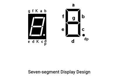
Theloads.numeric numbers are usually displayed solely on sevensegmentdisplays.IthassevenLEDbarsthatmaybe switched on by connecting the correct signals to the correctpins.WemustlightthecorrectportionsoftheLED inorderto geta specifiednumber. Todisplaythe number 3,forexample,wemustlightsegmentsa,b,c,d,andg.This meansthat a binary numbermay beconstructed fromthe patternoflightedandunlitsegments.
This pulse generator block's primary job is to transform the impulse generated by the energy metering chip into a digital pulse. The IC's pulse is nothing more than a peak impulse, which is then transformed into a square pulse. A high glow LED is positioned parallel to the LDR (Light dependent resistor) in this block, which flashes brightly whenever the chip receives a pulse. With the help of an LDR and an IC 555 timer configured in Bi stable Multi vibrator mode, this light energy is transformed into discrete electrical pulses. With the help of a Microcontroller, these pulses are handled as clock pulses for subsequent stages for counting/display purposes and monitoringenergyuse.
3.UsingIoT,relaydatatotheconcernedcellphone.
critical. The energy metering IC chosen here has a very high accuracy, allowing it to precisely measure and show the consumed energy. Power output can be utilized to drive heavy loads such as a water heater or an iron box, dependingonthethicknessofthecurrentsensorlinkedin series with the load terminals. The energy meter's overall circuitisdesignedtocreate pulsesinresponsetotheload suppliedtoit.
The semiconductor generates an analogue pulse, which is transformed to a pure digital pulse. The digital pulse generatorcircuitismadeupofanLDR,alightsource,and a 555 timer IC. The IC is set to operate in monostable mode, triggering at 1/3 and 2/3 of the operating voltage levels. The process starts with a pulse from the energy meter; whenever the meter generates a pulse, the lamp (LED)brieflyglows,andthelightintensityfallsontheLDR (Light Dependent Resistor), causing the voltage level to dropbylessthan1/3Vcc,triggeringtheICandgenerating a perfect square pulse. Instead of a bulb, a high glow LED canbeusedinthissituation.
International Research Journal of Engineering and Technology (IRJET) e ISSN: 2395 0056 Volume: 09 Issue: 03 | Mar 2022 www.irjet.net p-ISSN: 2395-0072 © 2022, IRJET | Impact Factor value: 7.529 | ISO 9001:2008 Certified Journal | Page578
3.2. Latch
Amatrixof28LEDsina744arrayisoneoption.Then,for whichever character we desire, we can light up selected LEDsinthepatternrequired.Anenlargedversionofthisis utilizedforfancydisplaysinavarietyofways.However,if allwewanttoshowarenumbers,thisgetsalittlepricey.A much better method is to arrange the smallest number of LEDs feasible in such a way that they only indicate numbers in a straightforward manner. This just necessitatestheuseofsevenLEDs.Acommonmethodisto utilizeandmouldedpieceof translucentplastictoactasa customized optical fiber, distributing the light from the LEDevenlyacrossafixedbarshape.
The high glow LED generates a dc voltage, which is fed to the light source. The input signal given by the Metering circuit determines how bright the LED glows. Low power transistors are used in the switching circuit to provide dc voltage to the light source. Either the positive peak or negative peak produced by the energy meter will be
The output of the energy metering circuit is sent to the pulse shaping circuit, which is calibrated at 1600 pulses per unit of electric energy consumption (therefore the display of 1600 pulses is equal to one unit of energy consumption).Steps:a)convertingpulsesintolightpulses; b) using an LDR, the light intensity falling on it is transformed into clock pulses; and c) creating the clock pulsesusinga555timerIC.Thefollowingarethespecifics: The output of the energy metering circuits (F1 and F2) is sent to a full wave bridge rectifier, which converts the frequencyinputintoproportionaldcvoltage.
A visible numeric display is a requirement for many different digital devices. Of course, individual LEDs can show the binary states of a group of latches or flip flops. We're more accustomed to thinking about and dealing withdecimalnumbers.Tothatend,we'dlikesomekindof display that can clearly depict decimal numbers without theneedtoconvertbinarytodecimaloranyotherformat.
International Research Journal of Engineering and Technology (IRJET) e ISSN: 2395 0056
4. CIRCUIT DESCRIPTION
3.4 Segment display
Volume: 09 Issue: 03 | Mar 2022 www.irjet.net p-ISSN: 2395-0072 © 2022, IRJET | Impact Factor value: 7.529 | ISO 9001:2008 Certified Journal | 579
Page
International Research Journal of Engineering and Technology (IRJET) e ISSN: 2395 0056
Volume: 09 Issue: 03 | Mar 2022 www.irjet.net p-ISSN: 2395-0072 © 2022, IRJET | Impact Factor value: 7.529 | ISO 9001:2008 580
Certified Journal | Page
transformed into a positive DC source using a full wave bridge rectifier with four diodes. Through a switching transistor, this source is used to energize the LED. The light intensity of this device will fall over the surface of LDRwhenevertheLEDisturnedon.BoththeLDRandthe LED are positioned parallel to each other The LDR is now connectedtoatimerchip,whichissettooperateinmono stable mode. The energization and de energization of the light source are translated into clock pulses. Pins No. 2 (TriggerPin)andNo.6(ThreshHoldPin)ofthe555timer IC are set to 1/3 and 2/3 VCC, respectively. As a result, anytime the voltage at Pins 2 / 6 is less than 1/3 VCC or greater than 2/3 VCC, state transitions occur. The resistance fluctuations of the light dependent resistor causethisvoltagevariation.Becauseofthelightlandingon it,thisLDRvariationoccurs.Asaresult,thetimer'soutput generates clock pulses in response to variations in light/resistance. As a result, the pulse shaping circuit generates clock pulses, which are required by the controllerforcountingandreportingenergyconsumption.
5. COMPONENTS
International Research Journal of Engineering and Technology (IRJET) e ISSN: 2395 0056 Volume: 09 Issue: 03 | Mar 2022 www.irjet.net p-ISSN: 2395-0072 © 2022, IRJET | Impact Factor value: 7.529 | ISO 9001:2008 Certified Journal | Page581
2 VoltageRegulator 3 555TimerIC 4 Wi Fimodule 5 LDR 6 IC74543 5.1.1 Arduino
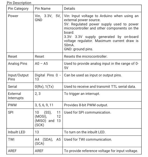
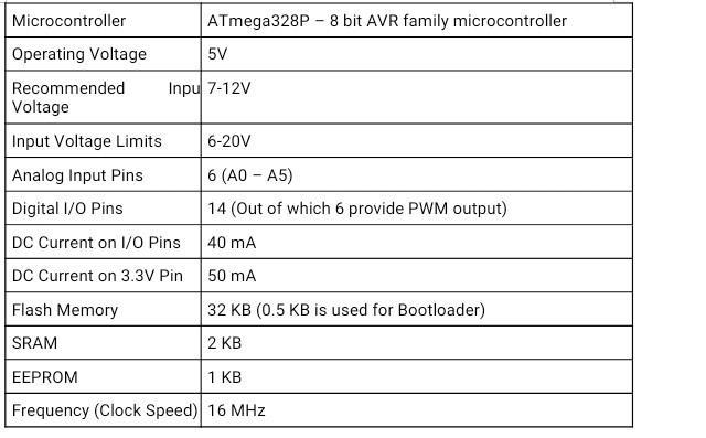
This chapter's goal is to collect data sheets for key components used in the project. Important information from the data sheet provided by the specific component manufacturer is acquired from websites and used in this chapter. The data sheets are displayed as individual Importantfolders. electrical components such as ICs, transistors, sensors, and other components must be interconnected over a well fabricated PCB for a stable and high quality output. The quality of components determines the performance of any well designed electrical circuit. The followingarethemajorcomponentsthatwereusedinthis 1project.Arduino Arduino is a simple software board, microcontrollers and microcontroller kits for making digital devices and interactive things with physical and digital sensing and Anyonecontrol. can distribute it. Commercially available Arduino boardsareeitherpreassembledorsoldasDIYkits.
5.1. HARDWARE COMPONENTS
International Research Journal of Engineering and Technology (IRJET) e ISSN: 2395 0056 Volume: 09 Issue: 03 | Mar 2022 www.irjet.net p-ISSN: 2395-0072 © 2022, IRJET | Impact Factor value: 7.529 | ISO 9001:2008 Certified Journal | Page582
It's surprising to learn that many individuals are unaware that Wi Fi stands for wireless fidelity. Even those who do aren't always aware of the meaning of Wi Fi. There are other theories regarding what the phrase signifies, but Wireless Fidelity is the most widely acknowledged meaninginthetechsector. Wireless technology has been quite popular in recent years, and we may connect nearly anywhere: at home, at work,at libraries, schools,airports,hotels,and evensome restaurants. Because it encompasses IEEE 802.11 technology, wireless networking is referred to as Wi Fi or 802.11 networking. Wi Fi's main benefit is that it works with nearly any operating system, game device, and modernprinter.
5.1.2. WI FI MODULE
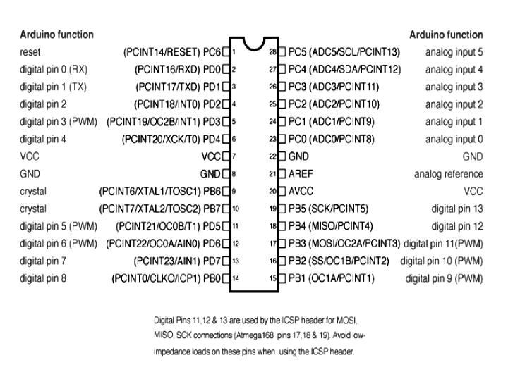
5.1.3. MICROCONTROLLER
Microcontrollers are single chip computers that have a central processing unit (CPU), data and program memory, serialandparallelI/O(input/output),timers,andexternal and internal interrupts. Microcontrollers are smart electrical devices that are used to operate and monitor real world devices. Microcontrollers are now found in nearly every piece of commercial and industrial machinery. Office automation, such as PCs, laser printers, faxmachines,andotherdevices,accountforabout40%of microcontroller applications. Consumer electronics products contain about a third of all microcontrollers. Productslike This includes CD players, hi fi equipment, video games, washing machines, and cookers. The other application areasincludethecommunicationsmarket, the automobile market,andthemilitary.
Awide range of microprocessorsandcontrollers are used in Arduino board designs. The boards provide digital and analogue input/output (I/O) pins that can be used to connect to expansion boards, breadboards (shields), and other circuits. Microcontrollers are often programmed using a dialect of C and C++ programming features. The Arduino project includes an integrated development environment (IDE) based on the Processing language project,inadditiontostandardcompilertoolchains.
Arduino is made up of a hardware programmable circuit board (also known as a microcontroller) and software, knownasanIDE(IntegratedDevelopmentEnvironment.
Themostsignificantdisadvantageofassemblylanguageis that different manufacturers' microcontrollers utilise differentassemblylanguages,requiringtheusertolearna newlanguageeachtimeanewprocessorisselected.
Arduino boards are utilized in a variety of electronic and telecommunicationapplications.Arduino isa single board microcontroller that may be used to customize applications, interactive controls, and surroundings. A boardbasedonan8 bitmicrocontrollerora32 bitARMis used as the hardware. A USB port, analogue inputs, and GPIO pins are all included in current models, allowing the user to connect additional boards. The acronym GPIO stands for General Purpose, Input, and Output. All of the CPUsweusehaveafew,andtheRaspberryPiandArduino both have a bunch of General Purpose Input Output that wecanusetocreateourcircuits. All Arduino boards are open source, allowing users to create them on their own and customize them to meet theirownneeds.Thesoftwareisalsoopen source,anditis evolving thanks to contributions from users all over the world.
Kevin Ashton of Procter & Gamble, later MIT's Auto ID Center, is thought to have invented the term "Internet of things"in1999,thoughheprefersthephrase"Internetfor things." He saw radio frequency identification (RFID) as critical to the Internet of Devices at the time, as it would allow computers to manage all of the individual things. Cisco Systems estimated that the Internet of Things was "born"between2008and2012.
In its most basic form, IOT system architecture comprises of three tiers: Tier 1: Devices, Tier 2: Edge Gateway, and Tier 3: Cloud. Devices are networked devices like sensors and actuators found in IoT equipment, especially those thatlink toanEdgeGatewayusingprotocolslikeModbus, Bluetooth,Zigbee,orcustomprotocols.EdgeGatewaysare sensor data aggregation systems that provide capabilities such as pre processing data, securing connectivity to the cloud,andevenedgeanalyticsorfogcomputingincertain circumstances, employing technologies such as Web Sockets, the event hub, and, in some cases, edge analytics or fog computing. The Edge Gateway layer is also needed to provide a common picture of the devices to the upper levels, making management easier. The cloud application designed for IoT using the microservices architecture, which are typically polyglot and inherently secure using HTTPS/OAuth, is the ultimate tier. It encompasses a variety of sensor data database systems, such as time series databases and asset stores that use backend data storage systems (e.g. Cassandra, PostgreSQL). In most cloud based IoT systems, the cloud tier includes an event queuing and messaging system that manages communicationacross all tiers. Thethreelevelsof theIoT system are characterized by some experts as edge,
5.3.2. APPLICATIONS 1.Smarthome 2.Medicalandhealthcare 3.Buildingandhomeautomation 4.Industrialapplications 5.Manufacturing 6.Agriculture 7.Energymanagement 8.Internetofmilitarythings 9.InternetofBattlefieldThings 5.3.3. ARCHITECTURE
5.3 DISCRIPTION OF WIFI MODULE Becauseoftheconvergenceofdifferent technologies,real time analytics, machine learning, sensors, and embedded systems, the definition of the Internet of Things has expanded. IoT technology is most closely associated with items that enable the concept of the "smart home" in the consumer market, which includes devices and appliances thatsupportoneormorecommonecosystems.
Microcontrollers are electronic devices that can be programmed. A program is a set of instructions that the microcontroller follows to do a certain task. Microcontrollers have typically been programmed in the target processor's low level assembly language. This is a setofmnemonicsthatcontainasuccessionofinstructions.
International Research Journal of Engineering and Technology (IRJET) e ISSN: 2395 0056
5.3.1. History
5.2. DESCRIPTION OF ARDUINO UNO PROCESSOR
The current vision of the IoT is based on Mark Weiser's 1991 paper "The Computer of the Twenty First Century," as well as academic forums such as Ubi=Comp and Pe Com.Between1993andthepresent,Severalfirms,suchas Microsoft's at Work and Novell's NEST, suggested solutionsin1997.WhenBillJoyproposeddevice to device communication as part of his "Six Webs" paradigm at the World EconomicForumin Davosin1999,thefieldgained traction.
Volume: 09 Issue: 03 | Mar 2022 www.irjet.net p-ISSN: 2395-0072 © 2022, IRJET | Impact Factor value: 7.529 | ISO 9001:2008 Certified Journal | Page583
• Cross platform The Arduino Software (IDE) is compatiblewith Windows, MacintoshOSX,andLinux. The majority of microcontroller systems are only compatible withPeopleWindows.whowant to learn more about the language can useC++libraries,andthosewhowanttolearnmoreabout thetechnicalspecificscanswitchfromArduinototheAVR Cprogramminglanguage.Similarly,ifyouwantto,youcan includeAVR CcodedirectlyinyourArduinoapplications.
4. Installation: The mechanical meter is quite sensitive to its installation location. It will run slowly if it is not installed vertically, resulting in revenue loss. Electronic metersaren'taffectedbywherethey'remounted.
2. Low Current Performance: After a few years, most electromechanical meters slow down and stop recording underlowloads,oftenlessthan40%oftheirbasiccurrent. Thisisbecausetheirbearingsarecausingmorefriction.
3. Low Voltage Performance: Mechanical meters lose accuracy at voltages below 75% of rated voltage, but electronic meters record accurately at 50% of rated voltage. This is a significant benefit in areas where low voltageissuesarewidespread.
The555hasthreemodesofoperation:
• Monostable mode: the 555 acts as a "one shot" in this mode. Timers, missing pulse detection, bounce free switches, touch switches, Frequency Divider, Capacitance Measurement, Pulse Width Modulation (PWM), and other applicationsareexamples.
• Bistable mode or Schmitt trigger: if the DIS pin is not connected and no capacitor is utilized, the 555 can function as a flip flop. Bounce free latching switches, for example,areoneapplication. 5.5. An overview of electronic energy meters
© 2022, IRJET | Impact Factor value: 7.529 | ISO 9001:2008 Certified Journal | Page584 platform, and enterprise, and are connected through proximity network, access network, and service network, respectively. 5.4. Timer chip description
5. Tamper: Mechanical meters may be tampered with extremely easily, even without disrupting the wiring, by introducingathinfilmintothemetertotouchtherotating disc, or by using an external magnet. In addition to these ways, there are more than 20 external wiring circumstances that can cause a single phase meter to record less data. External wiring on a three phase meter can be altered in four ways to slow it down. Electronic meters cannot be tampered with using any of these methods. They also use LEDs to show the existence of
Many new capabilities, including as prepayment metering and remote metering, are available with electronic meters, which can help the utility become moreefficient.
The 555 is an integrated circuit that can be used to implementanumberoftimerandmulti vibratorfunctions. The 555 timer is one of the most widely used and adaptable integrated circuits. On a silicon chip, it has 23 transistors, 2 diodes, and 16 resistors fitted in an 8 pin smalldual in linepackage(DIP 8).
6.tampering.NewFunctions:
6. WHY ARDUINO?
1. Accuracy: While electromechanical meters often have a Class2accuracy,electronicmeterswithaClass1accuracy arequitepopular.
Electrical metering device technology has advanced significantly since its inception more than a century ago. Many advances have resulted in size and weight reductions, as well as improvements in features and specifications, since the initial huge meters with hefty magnetsandcoils
International Research Journal of Engineering and Technology (IRJET) e ISSN: 2395 0056 Volume: 09 Issue: 03 | Mar 2022 www.irjet.net p-ISSN: 2395-0072
•Astable FreeRunningMode:The555canbeusedasan oscillator in this mode. LED and lamp flashers, pulse production, logic clocks, tone generation, security alarms, pulse position modulation, and other applications are all possible.
Thebenefitsofelectronicenergymetersareasfollows:
• Low cost When compared to other microcontroller platforms, Arduino boards are a bargain. The Arduino module'scheapestversioncanbeassembledbyhand,and evenpre madeArduinomodulescostlessthan$50.
c) The system is set up in such a way that energy theft is effectivelyavoided(totallytamperproof).
Solution: The bulky hardware can be transformed into a small integratedchipwhenthesystemisconvertedintoan engineering module. The system consumes less power whenthehardwareisdecreased.
Certified Journal | Page
Asmartenergymeterequippedwithamicrocontrollerfor safe data storage and processing capacity can be utilized for multiple purposes at the same time, making it a very versatile technology. Access control, data transmission, data storage, finance, and data carrier are common functional categories for smart energy meter applications. The system's principal application is AMR (Automatic Meter Reading System). State electrical bureaus would benefitgreatlyfromsuchsystems.
10. CONCLUSION
International Research Journal of Engineering and Technology (IRJET) e ISSN: 2395 0056 Volume: 09 Issue: 03 | Mar 2022 www.irjet.net p-ISSN: 2395-0072 © 2022, IRJET | Impact Factor value: 7.529 | ISO 9001:2008 585
7 ADVANTAGES
The project work on the "IOT based unattained tamper resistant energy meter" was finished successfully, and a prototype module was built for demonstration purposes, which is extremely close to the genuine operating system, with satisfactory results. The concept of a smart energy meter is a new trend in technology, and a wide range of
a) The meter is designed to generate pulses based on the amount of energy spent, allowing data to be saved and displayedindigitalsystems,ordatatobecommunicatedif b)necessary.Themeter's resolution is quite high, allowing it to correctlymeasurelowlevelsaswell.
d) Because of the digitalized display, human error can be e)eliminated.Finally,electronic meters offer a variety of innovative capabilities, such as prepaid metering and remote metering,thatcanhelptheutilitybecomemoreefficient.
9. APPLICATIONS
8. DISADVANTAGES. The main downside of the method is that it requires a smallamountofextraelectricenergyduetotheadditional electricalhardwareneeded.
International Research Journal of Engineering and Technology (IRJET) e ISSN: 2395 0056
(1)BeginningArduino MichaelMcRoberts
smart systems with various features are being developed. However, the system designed with IOT technology offers unique features, such as the ability to install the energy meter directly on the electric pole, where it cannot be tampered with in any way because it is not accessible to the energy user. Many more functionalities, such as identifying tampered energy meters, monitoring line voltage and load current, and so on, may be monitored remotelyusingthesamenetworkbecausethesystemuses IOT technology. If necessary, the user can turn off the powertothehousefromthesamephone,andmanyother capabilities can be added to the system. Power theft may becompletelyeliminatedbyinstallingthesetypesofsmart energymetersthroughoutthehomeandindustrialsectors for the benefit of energy users, saving the electricity departmentasignificantamountofmoney.
(2) GettingstartedwithArduino MossimoBanzi
Volume: 09 Issue: 03 | Mar 2022 www.irjet.net p-ISSN: 2395-0072 © 2022, IRJET | Impact Factor value: 7.529 | ISO 9001:2008
Certified Journal | Page586
11. REFERENCES