4 minute read
The functions listed above are the most critical functions of the Arduino unit, andthe program is set up to perform them correctly. Three common anode seven segment screens are used in the display portion, with a maximum power consumption of 9.99 units. A decimal point is included, and two digits are presented following the decimal point. As previously stated, the energy meter generates 100 pulses per unit, resulting in one unit being calibrated into 100 equal parts and counting in increment mode based on energy usage.

International Research Journal of Engineering and Technology (IRJET) e-ISSN: 2395-0056 Volume: 09 Issue: 03 | Mar 2022 www.irjet.net p-ISSN: 2395-0072
3.4 Segment display
Advertisement
A visible numeric display is a requirement for many different digital devices. Of course, individual LEDs can show the binary states of a group of latches or flip-flops. We're more accustomed to thinking about and dealing with decimal numbers. To that end, we'd like some kind of display that can clearly depict decimal numbers without the need to convert binary to decimal or any other format.
A matrix of 28 LEDs in a 744 array is one option. Then, for whichever character we desire, we can light up selected LEDs in the pattern required. An enlarged version of this is utilized for fancy displays in a variety of ways. However, if all we want to show are numbers, this gets a little pricey. A much better method is to arrange the smallest number of LEDs feasible in such a way that they only indicate numbers in a straightforward manner. This just necessitates the use of seven LEDs. A common method is to utilize and moulded piece of translucent plastic to act as a customized optical fiber, distributing the light from the LED evenly across a fixed bar shape.
4. CIRCUIT DESCRIPTION
The output of the energy metering circuit is sent to the pulse shaping circuit, which is calibrated at 1600 pulses per unit of electric energy consumption (therefore the display of 1600 pulses is equal to one unit of energy consumption). Steps: a) converting pulses into light pulses; b) using an LDR, the light intensity falling on it is transformed into clock pulses; and c) creating the clock pulses using a 555 timer IC. The following are the specifics: The output of the energy metering circuits (F1 and F2) is sent to a full wave bridge rectifier, which converts the frequency input into proportional dc voltage.

The high glow LED generates a dc voltage, which is fed to the light source. The input signal given by the Metering circuit determines how bright the LED glows. Low-power transistors are used in the switching circuit to provide dc voltage to the light source. Either the positive peak or negative peak produced by the energy meter will be
International Research Journal of Engineering and Technology (IRJET) e-ISSN: 2395-0056 Volume: 09 Issue: 03 | Mar 2022 www.irjet.net p-ISSN: 2395-0072
transformed into a positive DC source using a full wave bridge rectifier with four diodes. Through a switching transistor, this source is used to energize the LED. The light intensity of this device will fall over the surface of LDR whenever the LED is turned on. Both the LDR and the LED are positioned parallel to each other The LDR is now connected toa timer chip, which is set to operate in monostable mode. The energization and de-energization of the light source are translated into clock pulses. Pins No. 2 (Trigger Pin) and No. 6 (Thresh Hold Pin) of the 555 timer IC are set to 1/3 and 2/3 VCC, respectively. As a result, anytime the voltage at Pins 2 / 6 is less than 1/3 VCC or greater than 2/3 VCC, state transitions occur. The resistance fluctuations of the light dependent resistor cause this voltage variation. Because of the light landing on it, this LDR variation occurs. As a result, the timer's output generates clock pulses in response to variations in light/resistance. As a result, the pulse-shaping circuit generates clock pulses, which are required by the controller for counting and reporting energy consumption.

International Research Journal of Engineering and Technology (IRJET) e-ISSN: 2395-0056 Volume: 09 Issue: 03 | Mar 2022 www.irjet.net p-ISSN: 2395-0072
5. COMPONENTS

5.1. HARDWARE COMPONENTS
This chapter's goal is to collect data sheets for key components used in the project. Important information from the data sheet provided by the specific component manufacturer is acquired from websites and used in this chapter. The data sheets are displayed as individual folders.
Important electrical components such as ICs, transistors, sensors, and other components must be interconnected over a well-fabricated PCB for a stable and high-quality output. The quality of components determines the performance of any well-designed electrical circuit. The following are the major components that were used in this project.
1 –Arduino 2 -Voltage Regulator
3 –555 Timer IC
4 –Wi-Fi module
5 –LDR
6 –IC74543
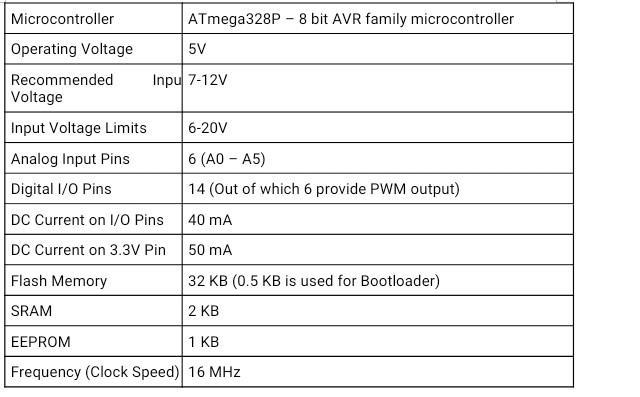
5.1.1 Arduino
Arduino is a simple software board, microcontrollers and microcontroller kits for making digital devices and interactive things with physical and digital sensing and control.
Anyone can distribute it. Commercially available Arduino boards are either preassembled or sold as DIY kits.