International Research Journal of Engineering and Technology (IRJET) e ISSN: 2395 0056 Volume: 09 Issue: 01 | Jan 2022 www.irjet.net p ISSN: 2395 0072 © 2022, IRJET | Impact Factor value: 7.529 | ISO 9001:2008 Certified Journal | Page408 Design and Analysis of Flywheel based Kinetic Energy Recovery System Jugal Budhlani1 , Mohit Bhutada2 , Siddharth Chhabria3, Harsh Bhutani4, Varun Peddi5 , Prof. Sunil Chougule6 1 5Department of Mechanical Engineering, Vishwakarma Institute of Technology, Pune, India. 6Professor, Department of Mechanical Engineering, Vishwakarma Institute of Technology, Pune, India. *** Abstract – Thepaperaimstopresentanalternatesystemof majorfinaltransmittedthroughmechanismThismaintenancecostincreasesvehiclesvehicles.mostkineticenergyrecoveryfromthewheelsduringbrakingfortheemergingsectorinmechanicalengineering,electricThemotorsusedwiththewheelsoftheelectrictodayarecapableofenergyrecoveryusingEMF,butitthecostofassemblylargely,andthusincreasestheofthecar.Italsoleadstolotofweartearandofthemotors,whichdecreasesthelifeofmotor.paperpresentsanalternatesolutionideatotheusingFlywheelengagementanddisengagementclutchsystem.Thepowerfromthewheelistotheflywheelthroughbeltdrivesystem.TheassemblyisdesignedinCADsoftwareSolidworks,andcomponentanalysisisdoneinANSYS. Key Words: Braking, analysis, alternator, flywheel, regeneration, inertia, structural, energy. 1. INTRODUCTION
Inthepresenttimes,whentheneedtoconsumeminimum energyisutmostimportantespeciallyinautomobilesector which primarily uses conventional sources of energy productionlikepetroleum,coaletc.Manyprogressionshave been made to improve efficiency of a vehicle by reducing input and maximizing output. The idea of Kinetic Energy Recovery Systems (KERS) promotes the same cause. The basicprincipleofworkingofKERSistorecovertheenergy lostduringbrakinginanautomobile.Theenergywastedis mostlylosttotheenvironmentthroughfrictionwhichleads toheatenergyalongthebrakes.TheaimofKERSistohelp restore thisenergylostduringbrakingandgiveit back to batterytoreuseit. KERSisasystemthatcollectsaportionofavehicle'sactive energywhenitisdecelerating,storesit,andthenreleasesit into the vehicle's drivetrain, giving it a boost in power. In thisdayandageofcutting edgetechnology,KERSoffersa wide range of applications. It is applicable in bicycles, bicycles,automobiles,andanyothermovingapplicationthat hasachangeinspeedasaresultofdeceleration,astheyare allbusinessandpracticalapplications.
2. LITERATURE REVIEW P. Veera Raju designed and fabricated Kinetic energy recovery system through mechanical brakes which demonstratea designedmodel in3DExperience software. Any auxiliary energy transfer or energy conversion equipmentmustbeefficient,compact,andreasonablypriced, andtheenergystorageunitmustbecompact,durable,and capableofhandlinghighpowerlevelsefficiently.Thischapter discusses the project's background, including the issue statement, objectives, and scope. All of this information is necessary to provide a starting point for the project's progress. The goal of this project is to use CATIA design softwaretobuildandfabricatearegenerativebrakingsystem employingmechanicalbrakes[1]. Thomas Matthews implemented the KERS system integrated in vehicles. The project used a flywheel for transfer of energy from moment of braking back to the batteryunit.TheflywheelKERSsystemhasthepotentialto beagame changingtechnology.Itincreasesthepowerofall vehicleswhilealsoimprovingtheirfuelefficiency.Acleaner, greenerenvironmentisdirectlyproportional toimproved fueleconomy.Ithasapositiveinfluenceontheenvironment sinceitminimizesdangerousCO2emissions.Thequantityof CO2emittedduringtheconstructionofoneflywheelKERS hasbeendeterminedtoberecoveredduringthefirst12,000 kmofdriving.Furthermore,unlikeahybridelectricvehicle, amechanicalhybridpoweredbyaflywheeldoesnotrequire thedisposalofhazardouschemicalspresentinbatteries[2].
eventualRegenerativefuelRegenerativebrakinghasalsobeendemonstratedtoenhanceeconomybyasmuchas20%atgreaterspeeds.brakingisaminorbutcriticalsteptowardourfossilfuelindependence.Batterieswiththesetypes
When compared to traditional stopping mechanisms, the KERSframeworkusedinautomobilesservesthepurposeof savingaportionoftheenergylostwhilebraking.Itcanalso beoperatedathightemperaturesandiseffective.Inorderto reduce energy loss, we assume that the topic KERS has a broad basis in the design field. The system can recover around30%oftheenergygiven,accordingtotheresultsofa segmentoftheexperimentsheoversaw. The use of more productive frameworks could result in massive reserve funds in any country's economy. We're assumingthatthetopicKERShasabroadbackgroundinthe designsectorinordertominimizeenergyloss.
Rohan Rane and Sandeep Mistry designedalight,compact andinexpensivesystem. Ina regenerative brakingsystem, theregenerativebrakerecoversaroundhalfofthewasted energyandusesittopowertheengine,whereastraditional brakessquander80%oftheoverallenergy.Aregenerative brakingsystemreducesfuelconsumptionby10%to25%.

Grossweightofvehicle(m)=800kg
Considering other frictional resistances (F) according to standardassumptions, = N
f
w
Total requirement of force (F) = 444.8+8.9+3.36+5 =
ρ
F=m
d
v
Let
Theaerodynamicdrag(FA)alsoaffectstheperformanceof thesystemanditisnecessarytoconsiderit. = C × × × 2, where C = coefficient of drag =0.5, = density of air = 1.25 kg/ 3 at 25℃, projectedarea=2.09 2
Wealsoneedtocalculatethespeedofthewheelforwhich diameterofwheel(DW)=228.6mm.
3. METHODOLOGY
A
3.1 WORKING OF THE SYSTEM
3.2 THEORETICAL
d
Fr
Ff
m.
μ×F
F×Rw
800
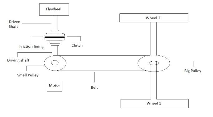
Fig 1:SchematicDiagram In electric vehicles, motor is the prime mover. Motor transferstheenergy tothe wheelswhichkeep thevehicle moving. Under normal circumstances, the KERS is disengaged from the main system comprising of motor, transmission,andwheels.TheFlywheelwhichwillbeused to regenerate is mounted on a separate shaft. The motor shaftandflywheelshaftarenotconnectedwhenthevehicle is running. Now, after applying brakes, transmission of pressure from the main master cylinder to slave cylinder pushes the clutch plate axially. This clutch plate comes in contactwiththefrictionplatemountedonflywheelshaftand itstartsrotating.Thekineticenergyofthewheelsthrough the same transmission system is now been transferred to flywheel via the engagement of clutch. The rotation of flywheelleadstoanincreaseinthemomentofinertiaofthe vehicle,whichhelpstodeceleratethevehicle.Thisrotational kineticenergystoredintheFlywheelcanthenbeconverted into electrical energy with the help of an Alternator. The spring which retracted due to application of brake comes backtoitsmeanpositiononcethebrakepedalisreleased, thus clutch plate and friction plate disengages and the vehiclecanbeacceleratedagainusingmotor. CALCULATIONS
A=
w
a
a=
m
w)=
International Research Journal of Engineering and Technology (IRJET) e ISSN: 2395 0056 Volume: 09 Issue: 01 | Jan 2022 www.irjet.net p ISSN: 2395 0072 © 2022, IRJET | Impact Factor value: 7.529 | ISO 9001:2008 Certified Journal | Page409 of brakes can be used for longer periods of time without needingtobechargedexternally.Thedrivingrangeoffully electric vehicles is also increased by using these types of braking systems When compared to a car with merely friction brakes, the regenerative braking system offers a numberofmajorbenefits.Theregenerativebrakingsystem canprovidethemajorityoftheoverallbrakingforceinlow speed,stop and gotrafficwherelessdecelerationisrequired. As a result, wecan see thatregenerative braking is a very promisingtopicwithmanyapplicationsinthenearfuture[3].
w
Butthegradisproportionaltothesquareofthevelocity,so theaverageofFAcanbecalculatedusingintegralfunction.
FA
5
444.8
ρ
To get the required force, the center of wheel needs to provideTorque(T ),whichcanbecalculatedby T = =54.83N
(0.5×m×v
Forthecalculationfortheenergystoredintheflywheel, usassumethattheflywheelstoresenoughenergytotake thewholesystemfromrest(u)tofinalvelocity(v)10km/hr in5sec. [(v u)/t]=0.556m/sec2 Energyofthesystemwhenitreaches10km/hr=E E= 2)=0.5× ×2.782 =3091.36J
Also,weknowthatthereisfrictionbetweentheroadandthe tireofthevehicleconsideringtherollingresistance = =0.02×448.8 =8.9N, hereμ=0.02for rolling resistancebetweenvehicletiresandroad
479.704N
Numberofrevolutions(NW)madebythewheelat10kmph persec NW=v/(2×π×Rw× 2.78/(2×π×114.3×7)=232.25rpm
m
The force (F) required taking the vehicle from rest to 10 kmphin5seciscalculatedasfollows: × =800×0.556= N
Fortheproposedsystem,eachandeveryprocessofdesign procedure for a project is followed. Starting with the schematic for finalization of idea and design is done. The designcalculationsreferringtostandardbooksandresearch aredoneinthenextpart.Asthecalculationsprovidedwith differentdesignparametersofeachcomponent,anassembly ofCADdesignisdoneinSolidworks20.

d=
torsional
Consideringfriction,80%ofKEisrequiredforbraking. KEb=0.8×111.2=89KJ WeneedtorecoverthisKEbwhichbelostinbraking. Assumingefficiencyoftransmissionofenergytobe0.25,we need to check if the flywheel is safe for this amount of energy.
T
3 (d
International Research Journal of Engineering and Technology (IRJET) e ISSN: 2395 0056 Volume: 09 Issue: 01 | Jan 2022 www.irjet.net p ISSN: 2395 0072 © 2022, IRJET | Impact Factor value: 7.529 | ISO 9001:2008 Certified Journal | Page410 Calculations of flywheel: The flywheel rotates at high speeds and it is necessary to calculatetheenergyitreleases(Efl)anditisformulatedas Efl =0.5×I×(ω12 ω22),whereω2 =24.31radians/sec And ω1 is constrained by the top speed of the vehicle, thereforeω1=146.22radians/secandIismomentofinertia offlywheel. Efl =0.5×I×(ω12 ω22)=10394.65×I Also the energy of the flywheel (Efl) will be consumed in bringing in bringing the vehicle into motion 10 kmph and overcometheresistances.UsingenergyasaproductofForce anddisplacementandreplacingdisplacementfromNewton’s thirdlaw. Efl =F×((v2 u2))/(2×a)=3333.9428J Comparingthesetwovalues I= But,0.32I=m×r2/2(forcirculardisc)and m=ρ×π×d2×t Constrainingthediameterofflywheel tothesizeofmotor diameter,wegetd=22.07cm ρ=7500kg/m3(Stainlesssteelmaterial)and thickness= 4cm=0.04m Mass of flywheel = 11.5 kg Now,aftergettingthedimensionsfromvariouscalculations, calculating various parameters of the clutch is also important. Also, considering design limitations, Outer diameter (Do) of clutch is restricted by Flywheel outer Ddiameter o=220.7mm Wehaveused Uniform wear theory foranalysis (Assuming thatthewearisuniformlydistributedovertheentiresurface areaofthefrictiondiskplate.) Mt=(π×μ×Pa ×d)/8×(Dd2 dd2),where Dd =outerdiameteroffrictiondisk=0.2207m Dd=innerdiameteroffrictiondisk= 0.112m p=intensityofpressureatradius,r=0.1N/mm P=totaloperatingforce(N) Mt =torquetransmittedbytheclutch=54.83N m Required spring force to keep the clutch in an engaged Pposition =(π×Pa×d)×(D d)/2 Bysubstitutingthevalues,weget, P= 1633.62 N
Calculations of Alternator: The energy that flywheel gets from braking needs to transferred back to the battery with minimal losses of the system.Alternatoristhedevicewhichcanbeusedforthis operation.Itisnecessarytocalculatetheamountofenergy andefficiencyofsystemtounderstandvalidityoftheproject.
M×y/I=114.91/d
(16T/πd3
��
Itisgivenby,T=Ks*(8×P×D)/(π×d3),whereKs=Wahl’s correctionfactor Ks=((4C 1)/(4C 4))+(0.615/C),whereC=springindex
Calculations of spring: Spring will be used to actuate the system when the brake pedalwillbeplaced.Stressesactingonthespringaredirect shearstressandtorsionalshearstress
σ
F
Substitutingallthevalues,d=18mm.
MaximumKineticenergy(KE)ofvehicle=0.5×m×v2 KE=0.5×800×16.672 =111.2KJ
d=
Torque=
Thematerialusedforshaftisstainlesssteelwhichhas yieldstrengthof215MPa.
N m Therefore
y=d/2
value
Wecan
Bendingmoment( ) = 3 ,where = × 11.2815, andI=(π/64)×d4
M
ConsideringC=6forbestmanufacturingconditions ThereforeKs=1.2525. Also,Pressure(p)=P/AwhereA=(π/4)×(0.32 0.262) andp=0.1N/mm2,wegetthevalueofspringforceas: P=1760N SpringsaremadeofoiltemperedsteelwithYield strength=1320MPa
shaft)
Calculations of shaft: StressesactingontheshaftaretorsionalShearstressand bendingmoment getthe of stress
��)
Itiscombinedloading;thereforewemakeuseoftheoryof failure.Inthiscase,MaximumShearstresstheoryof failure(Tresca’stheory)isapplied. max=�� permissible/FOS
Torsionalas:Shearstress( = ),where, shaft diameter, = 54.83 τ=279.24/d isdiameterof
Fig 2:Clutch brakesystemworking
ThespecificationsofHydraulicclutchareactuationpressure forclutchrangesfrom13 35bars.Themastercylinderbore diameteris22.5mmwhereasslavecylinderborediameteris 27mm.Thepressurerangeinhydrauliclinesduringpanic brakingis80 90bars.Thepressureinhydrauliclineduring normalbraking(inordertomakevehiclestop)isbetween 70 80 bars. Pedal ratio in vehicle for easier braking is 6. Pedalforcerequiredforpressureof80barsis500N.Pedal force required for 35 bar is 230 N. Mechanical advantage from linkage system between slave cylinder and clutch spring after calculations comes out to be 2.5. A hydraulic diagramforthesamemechanismisaddedtoshowclarityin workingoftheclutchbrakesystemthatisproposed.
4. ASSEMBLY OF THE COMPONENTS:
Instead of a mechanical connection, a hydraulic clutch mechanism employs a hydraulic line to convey pedal movement.Attheclutchoperation,apistononthemaster cylinderatthepedaltransmitspressuretotheslavecylinder piston via a fluid. A pressure value directs the flow of pressuretoclutch(13 35bar)andthentobrakeandclutch both(35 80+bar).
All the above components of the assembly have been designed in Solidworks software. The results of the calculations above have been used to create a Computer AidedDesignofeachmajorindividualcomponent Then, all the components have been combined into a Solidworksassembly,andcolorfulfeatureshavebeenadded toeachcomponenttomakethemodeleasilytounderstand andanalyze.
Fig 3:Hydrauliccircuitdiagram
International Research Journal of Engineering and Technology (IRJET) e ISSN: 2395 0056 Volume: 09 Issue: 01 | Jan 2022 www.irjet.net p ISSN: 2395 0072 © 2022, IRJET | Impact Factor value: 7.529 | ISO 9001:2008 Certified Journal | Page411 KEf =0.25×89=22.25KJ. Timeperiodoftransmissionconsideredis5seconds. Power=22.5/5=4.45KW. Now,alternatorisusedtoconvertthemechanicalenergyto electricalenergy. Outputvoltageofalternator=14.2V Ratedcurrent=300Amp Ratedrpm=3500rpm Outputpower=300×14.2=4.26KW Therefore,duetovariouslossesinalternatorsuchaseddy current losses and transmission losses, some amount of energyis Alternatorlost.losses=4.45 4.26=0.283KW Efficiency of system = = = 23.41% 3.3 WORKING OF CLUTCH BRAKE SYSTEM
Fig 4:Assembly(Isometricview)


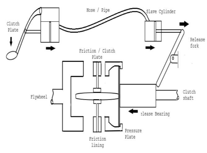
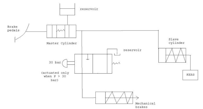
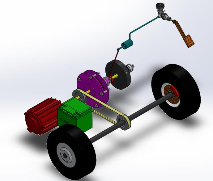
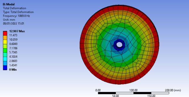
Table 1: Frequencyof
The Flywheel is tested for structural analysis and modal analysisintwomodes.Flywheelisonethemoststructurally strongcomponentofthesystemandhastheleastamountof chance to undergo failure. Material here considered in structuralsteel. Forstaticstructural analysisinANSYS, forces on flywheel aregravitationalforceandrotationduetoinertia(150 370 rad/s).Thesupportoftheflywheel isfixedsupportatthe axisofrotation.
ANALYSIS OF FLYWHEEL
Modalanalysisshowsthemovementofdifferentpartsofthe structure under dynamic loading conditions, and helps to determinethevibrationcharacteristics(naturalfrequencies andmodeshapes)ofamechanicalstructureorcomponent. In structural dynamics, the mode shape and natural vibrationshapeareemployed.Whenacomponentvibrates at its native frequency, its mode shape characterizes the deformationitwillexhibit.Thevibrationanddeformation, ontheotherhand,donotoccurunlessthereisanexcitation.
No. Mode Frequency (Hz) 1 1 1069.8 2 2 1762.1 3 3 1765.8 4 4 2664.7 5 5 3858.3 6 6 3860.2
Fig -7:NormalStressonFlywheel
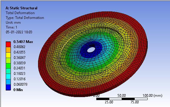
Fig 8:TotalDeformationofFlywheel
The entire vibration of a structural component, which is primarily made up of separate vibration forms, is determined by this excitation. So the data from static structuralisthenimportedtomodalanalysistoolinANSYS andtheresultsareobtainedfordifferentmodesofvibration modesofvibration
International Research Journal of Engineering and Technology (IRJET) e ISSN: 2395 0056 Volume: 09 Issue: 01 | Jan 2022 www.irjet.net p ISSN: 2395 0072 © 2022, IRJET | Impact Factor value: 7.529 | ISO 9001:2008 Certified Journal | Page412 Fig 5:Assembly(Topview) Fig -6:Clutchassembly 5. ANALYSIS OF THE COMPONENTS: Someofthecomponentsintheassemblywillbesubjectedto lotsofthermalandstructuralstresses.Hence,properanalysis isrequiredwithall thegivenconditionstosimulateunder variouscases of failure. Thiswill assure thatthesystemis free from failure The Analysis of the components of the systemisdoneinANSYSWorkbenchsoftware.
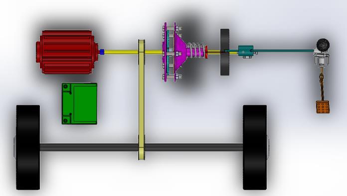
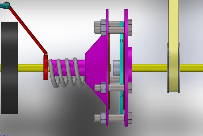
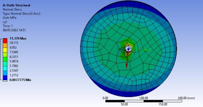
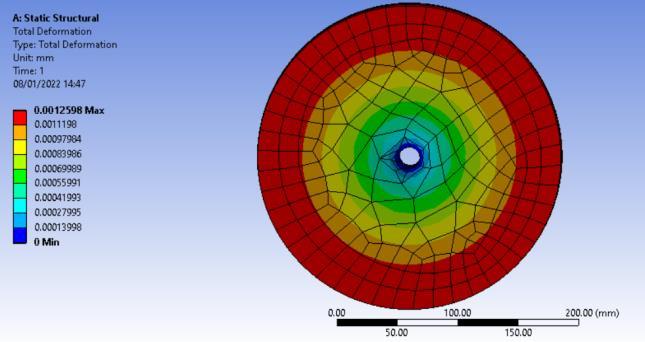
Fig 13:EquivalentStressonclutch
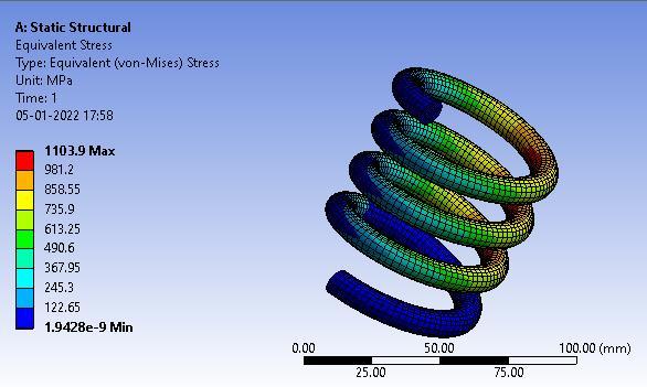
Fig 11:EquivalentStressonspring
ANALYSIS OF CLUTCH Clutchisusedtoengagethedriveshaftwiththeflywheelto transferthekineticenergy ofthewheelstoFlywheel. The outerdiameterofclutchis0.2207mwhileinnerDiameteris 0.1314 m and the thickness is 8 mm. The material for the clutch is Asbestos (Density= 2000 kg/m3, Coefficient of friction =0.25). The boundary conditions are: 1. Fixed supportatInnerDiameter.2.Uniformpressureof0.1MPa overthefrictionsurface
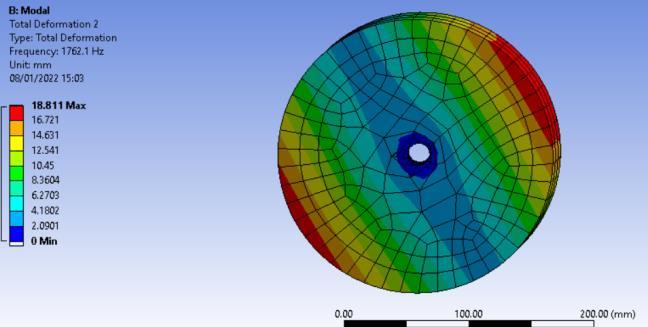
International Research Journal of Engineering and Technology (IRJET) e ISSN: 2395 0056 Volume: 09 Issue: 01 | Jan 2022 www.irjet.net p ISSN: 2395 0072 © 2022, IRJET | Impact Factor value: 7.529 | ISO 9001:2008 Certified Journal | Page413 Fig -9:TotalDeformation(Mode1) Fig 10:TotalDeformation(Mode2) FromtheANSYSstaticstructuralandmodalanalysisdatawe cansee: Totaldeformationformaxrotation=0.00125mm Normalstress=12.081MPa Safetyfactor=14.38 Deformationat1st modeofvibration=12.08mm Deformationat2nd modeofvibration=18.81mm
The above data show that the design of the flywheel is completelysafe.
ANALYSIS OF SPRING Spring is required to actuate the mechanism so that the pressureplateofclutchisincontactwiththefrictionplate through which energy is transferred to the flywheel. The materialofthespringisoiltemperedsteel. SpringForcerequired:1760N MeandiameterD=60mm Coildiameter=10mm Boundary conditions: One end is fixed, Load of 1760 N appliedontheotherend.
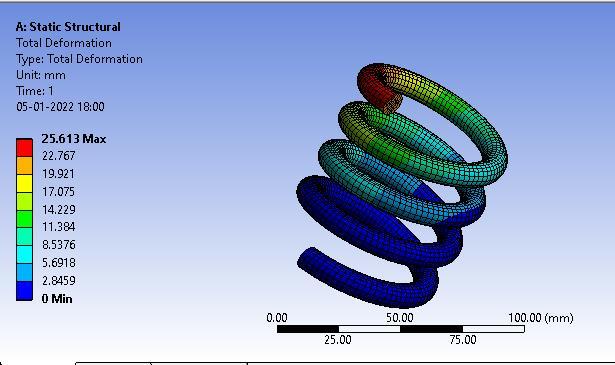
Fig 12:TotalDeformationofspring. From the ANSYS analysis results, we get the value of maximum stress=1104 MPa and maximum deformation= 25.613mm
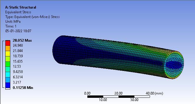
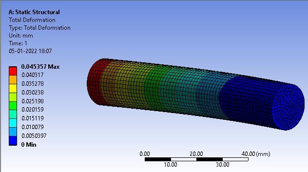
From the ANSYS analysis results, we get the value of maximum stress=28.05 MPa and maximum deformation= 0.045mm
[5] Zafar Anwar and Nilanjan Sen, “Mechanical Design calculationsofflywheelgenerator.”Conferencepaper, Dec.2019.
Alltheimportantcomponentswhicharecontinuouslyunder various types of stresses are modelled and analysed in ANSYS for the types of stresses and total deformation the component will go, if subjected to maximum loads. From various ANSYS results, we can conclude that every componentdesignissafeandisinthesaferangeoffactorof safety.
Fig 15:Equivalentstressonshaft Fig 16:Totaldeformationofshaft
[3] RohanRaneandSandeepMistry,“Design,Analysisand fabricationofregenerativebrakingsystem.”Science,vol. 4issue8,Nov.2016,pp.368 374.
International Research Journal of Engineering and Technology (IRJET) e ISSN: 2395 0056 Volume: 09 Issue: 01 | Jan 2022 www.irjet.net p ISSN: 2395 0072 © 2022, IRJET | Impact Factor value: 7.529 | ISO 9001:2008 Certified Journal | Page414
[1] P.VeeraRajuandB.L.Krishna,“DesignandFabrication ofKineticEnergyRecoverySystemthroughMechanical Brakes”Science,vol.7issue3,March2020,pp.63975.
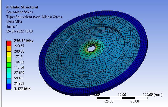
ANALYSIS OF SHAFT
Fig 14:Totaldeformationofclutch.
REFERENCES
[2] Thomas Matthews,” Flywheel based kinetic energy recoverysystem(KERS)integratedinvehicles.”Science, vol.5,Sept.2013,sp.1694.
Diameteroftheshaftonwhichtheflywheelissupportedis 18mmmadeofstructuralsteelwithyieldstrengthof215 MPa.Theboundaryconditionfortheanalysisisthattheone endoftheshaftisfixed Aloadof138Newtonisappliedon theotherend.
[6] StevenCarlin,“AnAnalysisofKineticEnergyRecovery SystemsandtheirpotentialforcontemporaryInternal CombustionEnginepoweredvehicles.”unpublished.
An introductory design of the kinetic energy recovery system (KERS) is carried out. The design contains every aspect of transmission and regeneration from otherwise wastedbrakeenergy.Aschematicexplainingconceptofthe project has been added. All the design calculations are carried out according to standard reference books. Each componentismodeledinSolidworksandthenassembled. EverymajorcomponentisanalyzedinANSYStocheckifit failsinanycondition.Theefficiencyofthesystemcomesout around 23.4%, which is in good range compared to how Teslaproposesitsexperimentedsystemat30%.Withbetter experimentations,useofbettermaterialsandmoreanalysis, this project surely aims towards higher regeneration of wastedenergy.Theproposedideaanddesignpresentedin this paper will hopefully trigger cheaper and affordable electricvehiclesintheindustry.
[8] Bhandari, V., 2010. Design of machine elements. New Delhi:TataMcGraw Hill.
From the ANSYS analysis results, we get the value of maximumstress=256.73MPaandmaximumdeformation= 0.54mm.
[4] Shreemoy Kumar Nayak, “Design of kinetic energy recoverysystemforbicycle.”unpublished.
6. CONCLUSION
[7] KevinLudlum,“OptimizingFlywheelDesignforuseasa Kinetic Energy Recovery System for a Bicycle.” unpublished.