International Research Journal of Engineering and Technology (IRJET) e ISSN: 2395 0056 Volume: 09 Issue: 01 | Jan 2022 www.irjet.net p ISSN: 2395 0072 © 2022, IRJET | Impact Factor value: 7.529 | ISO 9001:2008 Certified Journal | Page356 Design and Manufacturing of Gearbox for Four-Wheel Steering Bhavesh Nandpure1 B.Tech Mechanical Engineering, MPSTME, Maharashtra, India *** Abstract
1.3. Types of Steering Mechanism
The steering mechanisms are classified based on their geometry. They are Davis steering mechanism and Ackermann steering mechanism. Davis steering system consistsofslidingpairswhichwearsoutduetofrictionand hencechangestheaccuracywithtime.Ackermannsteering systemconsistsofturningpairshenceithasbetterlifeasit does not wear easily. Therefore, Ackermann is most preferred mechanism for steering. In Ackermann steering system the end of the axle has a spindle that attaches to kingpin. The linkages form a shape of trapezoid after connecting spindle. When the front and rear wheels get parallel,theyareinstraightline.However,whenwheelsare turned, inner wheel turns by greater angle than external causingexternalwheeltocoveragreaterdistancethaninner wheel.Theamountofsteerangleisdependentontheratioof trackwidth and wheelbase in Ackermann based steering system. The system holds true for left, right and straight positionbutconsistsofsmallerrorinotherpositions
1.2. Working of front wheel Steering system
The steering wheel is used to rotate the steering column whichlaterrotatesthegearsingearboxattheendofcolumn. Thecrossshaftingearboxisconnectedtodroparmanditis connectedtosteeringarmsbymeansofdraglink.Thearms operatethetierodswhicharejoinedtoknucklethatmoves thewheelleftandright.Aballsocketjointisusedtojointie rodanddroparm.Incaseofvibrationswhiletravellingdrop armvibratesandthereforespringsareusedinballsockets to damp vibrations from the surface of roads to steering wheel.
The paper discusses about the design and production process of 4 Wheel Steering system. The basic motive behind this research is to improve the steering ability and effort required while turning the vehicle. This prototype of gearbox will reduce the turning radius of vehicle, manoeuvre in different terrains easily, and increase the stability of steering wheel while driving vehicles at high speeds. In this paper we have designed and discussed the manufacturing techniques of designed gearbox through which 4 Wheel Steer can be achieved. By using this system, it is possible for driver to control angles of four wheels. In this steering mechanism rear wheels turns in opposite direction with respect to front wheels at slow speed conditions while turning. This will result in low turning radius and prevent sliding on slippery terrains such as snow and rain covered roads. Similarly, at high speeds another gear system will get engaged, which will turn the rear wheel in the same direction as of front wheel providing a smooth turn at high speeds. An attempt is made to formulate this gear box by using rack and pinion steering system with certain controllers and actuators to automate the gear engaging process. The paper shows a methodology to achieve a suitable manufactured prototype of four wheel steered gearbox and discuss the benefits of this system.
1.4. Problems with Front Wheel or 2WS system: Therearevariousautomaticcontrolledsystemsinmodern vehiclestoreducetheeffortsofdriver.Buttheautomation foundinsteeringcontrolislesswhileitplaysamajorrolein safetyofpassengers. Almostmajorityofpeopleintheworld stillhavevehicleshavingfrontwheelsteeringsystemwhich causesseveralproblemssuchas,whenitcomestoturningof vehicleforparkinginnarrowspacesorinparallelparking condition.Themostofthedriversfinditquitecumbersome and difficult to park as they require to steer the wheels frequently. As they steer to turn, they move the wheels at variousanglestoooften,butcouldonlyachieveasmallturn astherearwheelsarealways straight.Hence,most ofthe
Key Words: Turning Radius, Spur Gear, Bevel Gear, Gear box,RackandPinion,Wheelbase,andTrackwidth.
1.1.1.INTRODUCTIONWhatisasteering system? Steeringsystemisagroupoflinkagesbetweencomponents thatturntherotarymotionofsteeringwheelintoalinear motion,accompanyingthewheelsofthevehicletoturnat different angles either on right or left side. The steering systemincludesadrivercontrolledsteeringwheel,motion conversionsteeringgeartotranslaterotarymotiontolinear motion,andthesteeringlinkagesthattransmitmotionfrom steeringwheeltowheels.Themostcommonlyusedsteering systemtypesarerackandpinionandrecirculatingballtype. Thesesystemsusedtobemanualtypeearlierbutnowadays almostallvehicleshavepowersteering,whichisconvenient toreducethesteeringeffortofdriver.Thebasiccomponents of power steering system include steering wheel, steering anglesensor,speedsensor,inputshaft,intermediateshaft, tie rods, knuckle, steering gear assembly, steering shaft electroniccontrolunit(ECU),solenoidvalve,oilpump,tank etc.Thegoodsteeringsystemhasgoodaccuracy,lightand easytohandle,directionalstability,minimumturningeffort, lessornoshocktransmissionfromroadsurfacetodriver’s hand. The general arrangement of every steering system contains steering wheel, steering column, steering shaft, steeringgearbox,droparm,pullandpushrodordraglink, knucklearm,Tierod.

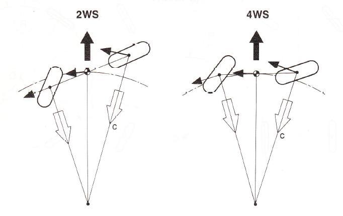
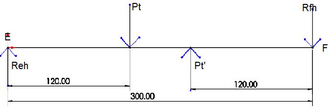
Fig 1.2 In phasesteering(athighspeed)
Another common scenario where front wheel system fall short is during turning of vehicles at high speeds. At high speedsdriverhavetoreducethespeedofvehicletotakea turn so that they maintain stability of vehicle and vehicle doesnotgetskidoffthetrack.Thisscenariohasremaineda disadvantage for racing drivers for years who need to constantlydecelerateandacceleratethevehicleatturnsor while switching lanes on tracks. The turning radius has alwaysremainlargeforthefrontwheelsteeringsystemand sonowthereisa needofreplacementofthissystemwith newallwheelsteeringsystem.
International Research Journal of Engineering and Technology (IRJET) e ISSN: 2395 0056 Volume: 09 Issue: 01 | Jan 2022 www.irjet.net p ISSN: 2395 0072 © 2022, IRJET | Impact Factor value: 7.529 | ISO 9001:2008 Certified Journal | Page357
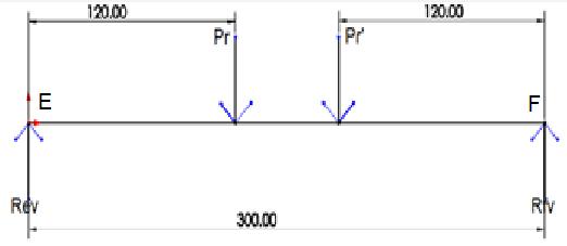
Similarly,athighspeedsanothergeararrangementwillbe used, where rear wheels will turn in same direction as of frontwheel,providingasmoothturnathigherspeeds.This turningof4WSsystemisalsotermedas‘In phase’(athigher speeds) and‘Counter phase’ (atslowspeeds) asshown in figure1.1and1.2.
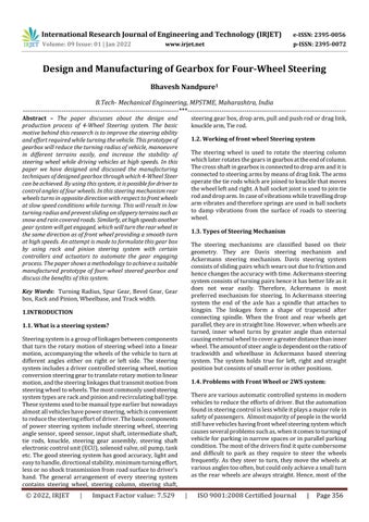
Fig.1.1 Counter phasesteering(atslowspeed)
A4WSsystemconsistsoffrontsteeringcontrolledbypower steeringsystemwhichcanbeeitherhydraulicorelectronic and at rear there is a rear steering mechanism which is controlled by means of gearbox or gear arrangement depending on the speed of vehicle and steering angle of wheel.Theelectronicformoftransmittingmotionthrough hydraulics can also be done in rear steering mechanism which is termed as rear power steering. In this system at rear a gear used for reciprocating rack, consists of spring whichalwaysreturntoitsinitialpositionafterturning.This assuresthattherearwheelsremainstraightafterturningis completed,thespringusedhereistermedasself centering springwhichplaysacrucialrolewhenthereisafailureof hydraulic system of rear power steering. As the self centering spring brings back the pinion to initial position makingtherearwheelstraightsafterturning,thefailureof hydraulicswill nothavesignificant effectwhileturning as thefrontwheelcanbeeasilysteeredorgettransformedto 2 WheelSteering(2WS)systemafterfailureof4WS. Ourdesigned 4WSmechanismconsists ofrackandpinion mechanismatfrontandrear,wherefrontrackiscontrolled by driver and the rear rack is controlled by a gear arrangementconsisting4spurgearsand3bevelgearswhich isconnectedtoelectroniccontrolunit,actuatorsandsensors tooperateitselfdependingonthespeedofvehicleandangle of front steer. The rear wheels turn in opposite direction withrespecttofrontwheelsinslowspeedconditionswhile making a turn. This will result in low turning radius and prevent sliding or skidding of vehicle off the track. In addition, when they turn in opposite direction at slow speeds,theycouldachieveagoodgripbetweenroadsurface andtiresresultingnoslipinsnowyterrains.Also,itwillbe beneficialwhiledrivingonhillyareaswhereturnsarequite sharpandincitiesorcongestedareaswhiletakingU turn.
The basic motive behind 4 Wheel Steering system is to improve the steering ability and decrease effort required while turning vehicle. The designed all wheel steering gearboxwillreducetheturningradiusofvehicle,manoeuvre in different terrains easily and increase the stability of steering wheel while driving at high speeds. We have designedandmanufacturedanautomatedgeararrangement or gearbox through which four wheels can be steered. By usingthissystem,itispossiblefordrivertocontrolanglesof allfourwheels.
driversfeelparkingtiresomeactivitydespitehavingparking assistance,360˚vehicleview,frontandbacksensors.
The above problems can be solved by using a 4 Wheel steering system, where the angles of all wheels can be adjusted automatically or manually using a special gear arrangement 1.5. What is 4-Wheel Steering (4WS) system?
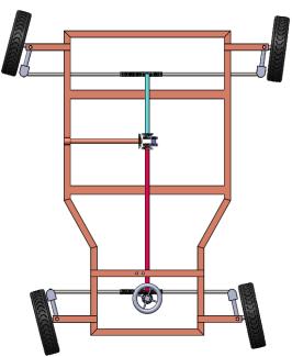
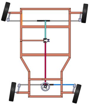
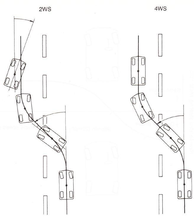
Fig.1.3 Differenceinturningradiusof2 Wheelorfront Wheelsteeringand4 Wheelsteeringsystem[4] For 2WS the turning radius can be seen to be large when compared with 4WS. The significant change is seen in positionofpoint‘O’inthefigurewhichisalsoInstantaneous centerofrotation(ICR).Thepoint‘O’remainedontheaxisof rearwheelsin2WSwhichresultedinmoreturningradius andgreaterwidthtotaketurn.Whilein4WStherearwheel turned in opposite direction with respect to front wheel, changing the position of ICR to middle. Hence, from geometry it can be seen that the turning radius and the widthtotaketurnisreduced.Thisconditionholdstruefor slowspeedstotaketurnonnarrowpassesandU turns.
1.6.2 High speed Turning Vehiclesrequiremorecorneringforce(C)athighspeedsto balancecentrifugalforce,whichismoreforvehicleathigher speedtakingaturn.Asthecorneringforceincreasestheside slipanglealsoincreasesfor2WSsystem.Butin4WSsystem asrearwheelsgetssteeredonsamecurvewithfrontwheels athighspeeds,itreducesyawingofvehicleandpreventit from moving outside the curve. This results in reduced yawingtimeortimetogetstabilizedandreductioninslip angle. The side slip angle is greater for 2WS system than 4WSsystem.
Fig.1.5. Lanechangescenariofor2WSvs4WS[4]
Thelengthoftimerequiredby2WSsystemtostabilizerear wheel is more than 4WS system. As the 2WS system goes yawing while changing lane it needs to be steered in oppositedirectionsothatrearwheelsgetalignedquickly.In caseof4WSsystemithasgoodbalancewhilechanginglanes andhasaprecisesteeringatcorners,astherearwheelsalso gets steered independently with respect to front wheels decreasingthechancesofstumbling.
Fig.1.4 Differenceincentrifugalandcorneringforceacting in2WSand4WSathighspeeds[4]
1.6.3 Lane change
2. DESIGN AND CALCULATIONS
The designing and manufacturing of gear box is implemented for the standard hatchback vehicle with the dimensions given below. In the paper I have taken into consideration the standard dimensions of Maruti Suzuki Alto.However,asimilarprototypewasdesigned withsame gear arrangement, dimensions and is tested for the four
International Research Journal of Engineering and Technology (IRJET) e ISSN: 2395 0056 Volume: 09 Issue: 01 | Jan 2022 www.irjet.net p ISSN: 2395 0072 © 2022, IRJET | Impact Factor value: 7.529 | ISO 9001:2008 Certified Journal | Page358 1.6. Benefits and need for 4 Wheel Steering System 1.6.1 Low Turning Speeds
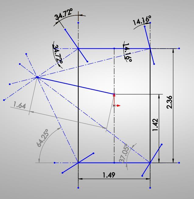
International Research Journal of Engineering and Technology (IRJET) e ISSN: 2395 0056 Volume: 09 Issue: 01 | Jan 2022 www.irjet.net p ISSN: 2395 0072 © 2022, IRJET | Impact Factor value: 7.529 | ISO 9001:2008 Certified Journal | Page359 wheeldrivesystemforitsimplementation.Itwaslaterfound tobesuccessfulandbelowarethecalculationsshownforthe prototype. 2.1 CALCULATIONS Wheelbase(L)=2.36m Trackwidth( )=1.49m TurningRadius(R)=4.6m TotalWeight(W)=750kg LoadonFrontAxle( )=450kg Loadonrearaxle( ) =300kg 1) AckermanAngle(α) ˚ ByAckermanMechanism, Where, =innerangleoffrontwheel Y=Armbase=1.2435” X=LinearDisplacementin1rotation=3.5” R=TieRodLength=6” 2) ForPositiveSteeringGeometry …………………….(1) RWhere,=turningradiusofwheel=4.6m =DistanceofC.Gfromrearaxle =DistancebetweenICRandaxisofvehicle …………………..(2) From(1)and(2) =1.416m=1416mm, =4.376m4376mm 3) =DistanceofICRfromfrontaxleaxis =DistanceofICRfromRearaxleaxis ………………..(4)…………………(3) SolvingEquation(3)and(4) 4) 5) Now,bytakingsamesteeringanglesforfrontand reartireswewillreduceturningradiusofvehiclebut bywewillkeepwheelbaseandtrackwidthsame. ……………(6)……….(5) SolvingWhere,equation(5)and(6) , R= 2.14m =1.416m,andR=2.14m 6) …………..(7)……………(6) R= 2.14m, , Solving(6)and(7)(InsidelockangleofFrontWheel) (OutsidelockangleofFrontWheel) (InsidelockangleofRearWheel)


International Research Journal of Engineering and Technology (IRJET) e ISSN: 2395 0056 Volume: 09 Issue: 01 | Jan 2022 www.irjet.net p ISSN: 2395 0072 © 2022, IRJET | Impact Factor value: 7.529 | ISO 9001:2008 Certified Journal | Page360 (Outsidelockangleof(RearWheel) =95.8˚(Totalinnerangleofvehicle) (Total outer angle of vehicle) ……………(9)……….(8) Solvingequation(8) Solvingequation(9) R= 1.70 m Thefigure2.1showstheanglesofthefrontwheelswhich willbetheinputparametersinoursteeringsystem.To locateInstantaneousCentreofRotation(ICR),wehave drawn a perpendicular line from centre of front axle. Then similarly the steer angle of rear wheels was checked where they come out to be approximately the same. For example, , and ,butinFigureit wasfound and whichare nearlythesame.Inthesameway,thedistanceofCGfrom rearaxle( islocatedandverifiedforturningradiusit isequalto1.64(fromfigure)and1.70(fromcalculations) Fig.2.1. LineDiagramforcalculatedvaluesof4WS 7) Steeringratio(n) a = Steering wheel angle = 360˚ (for one rotation of steeringwheel) 8) RackandPinionCalculation ForPinion, α=PressureAngle=20˚ =fractiontomultiplyaddendumofwheel=1 ==1.661.5 (T) 14teeths ForRack,Linear Displacement of rack for 1 Rotation of pinion= =141.37mm PCD=PitchCircleDiameter=m =45mm MountingDistance=55mm(fromDesign) H=Rackheight WeKnow, 9) BevelGearCalculation =70 = =90 =PitchCircleDiameterofPinion =PitchCircleDiameterofGear α=PressureAngle=20˚ =UltimateTensileStrength=700MPa =1.5 Y=LewisFormfactor =WearStrength


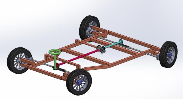
International Research Journal of Engineering and Technology (IRJET) e ISSN: 2395 0056 Volume: 09 Issue: 01 | Jan 2022 www.irjet.net p ISSN: 2395 0072 © 2022, IRJET | Impact Factor value: 7.529 | ISO 9001:2008 Certified Journal | Page361 BHN=Brinellhardnessnumber k=Loadstressfactor =88.67 =0.4412 =233.33 =m =105mm =m =135mm =85.51mm =1909.95 WearStrength =1.246 =2.6896 =6686.3N 10) Spur==Gears700Mpam=75mm =m =87.5mm =12.5mm =233.33=1534.87N =k1.077=2715.65N KW=Powertransmittedbygears=0.05KW=50Watts n=numberofrevolutions=10rpm(Assumed) bygears =Tangentialcomponentoftoothforce =Radialcomponentoftoothforce =47746.48N mm =1273.24N = tanα=463.42N =1273.24N =463.42N b)a) ×120+ ×300= ×180 = + 2.2 DESIGN The prototype is designed using Dassult Systems SolidWorks. Fig.2.2. Assembled4WSinSolidworksRendering


for
3.1Manufacturing processes used for Steering Components
Droparmismanufacturedusingforgedsteel.Ithassplines whichattachessector shaftbynutandotherendwithball jointsandnut.
for
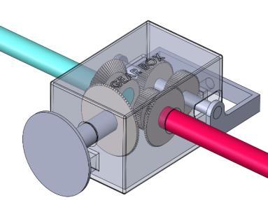
Fig.2.5. GearBoxDesign Solidworks
Steeringgearboxconsistsofcasingmadeofaluminiumand gearsare either bevel,spur, rack andpiniontypemade of high strength steel or cast iron. Its function is to convert rotarymotiontolinearmotionandisconnectedtodroparm.
FollowingproductionmethodsareusedformakingSteering Components
After studying the Circuit Diagram of Alto 800, I came to knowthatC02 4 40wasthemoduleresponsibleforpower steering unit in Maruti Suzuki Alto. So, if the changes in circuit have to be done in future this module needs to be replaced.ThismodulecarriesfunctionofVSS(Vehiclespeed sensor)andmeasuresthetransaxleoutputofspeedofthe wheel.Byusingspeedofvehicleasinputthefunctionssuch asignitiontiming,air fuelratio,transmissionshift,actuating steeringfor4WScanbeadjusted.
Steering wheel is manufactured using steel ring that is weldedonhubwithcertainspokes.Theeboniteismoulded afterweldingthewheeltoenhancelookandprovidegripto hands. Then splines and groove are created at bottom to attachtoshaft. Steeringcolumnisahollowsteelpipeofmildsteelwhichis housedwithoutercasing.Oneendofpipeisattachedtogear boxofsteeringandanothertobracket Steering shaft is manufactured using good quality steel, where one end is inside steering wheel and the other has splinesorkey lockarrangementtokeepitattachedbyworm orbevelgearofgearbox.
International Research Journal of Engineering and Technology (IRJET) e ISSN: 2395 0056 Volume: 09 Issue: 01 | Jan 2022 www.irjet.net p ISSN: 2395 0072 © 2022, IRJET | Impact Factor value: 7.529 | ISO 9001:2008 Certified Journal | Page362
3. MANUFACTURING PROCESS INVOLVED
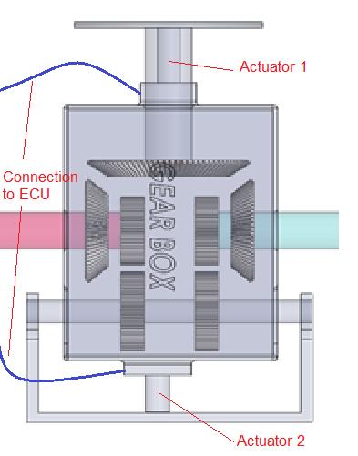
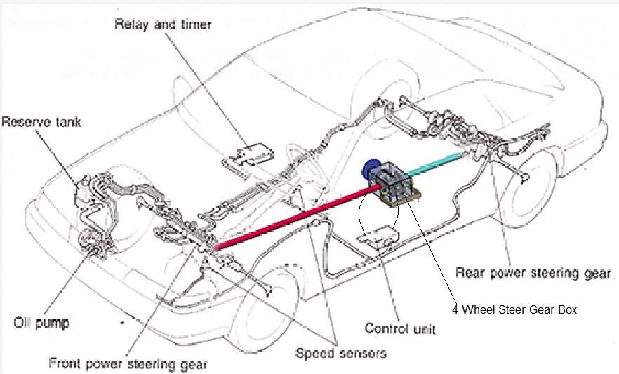
Fig.2.6. TechniquetoImplement4WSGearBoxinan AutomobilewithSensorpositions
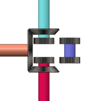
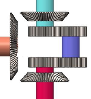
Fig.2.3. Arrangement gear In phase Fig.2.4. Arrangementofgear Counter Phase
Steer
of
in
Rendering
Rapidmaterialremoval rate SlotDrills Producing pocket for drillingholes
It has a cross section with milling teeths used to create desired shape. Also known as specialised milling machine
Theshapingandplanningoperationscanbealsodoneusing milling machine. Various cutting tools are used in milling machinefor various purposes such as Slab mills, Side and facecutters,Slittingsaws,EndMills,Slotdrills,Involutegear cutter,Hobbingcutteretc.Beforesendingourgearsforheat treatmentwewillbemachiningthemroughlyandgenerate teethsusingHobbingcutter.Thisprocesswillbecarriedon millingmachine.
EndMills
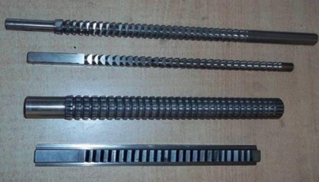
3.1.1. Broaching
It is a metal cutting process, where metal is removed by slenderrodhavingseriesofcuttingedges.Ithasincreasing protrusioncontainingnumberofcuttingandfinishingteeths. Broaching makes it feasible to remove the entire non required material in a single stroke, as it has increasing heightfrombottomtotop. Straightthoroughholescan be created using this tool. The broaching is used in creating externalandinternalteethsofspurgears.Thetwotypesof broachesuseddominantlyareofpushandpulltypes,they are made of various cross sections and rising heights of teeths. Push type broaches are usually short in length to preventthemfrombucklingduetocompressiveforceonit. The materialsused to make broacheshave goodstrength, wearresistance,toughness,andhardness.Themostofthe typicalmaterialusedtomakebroachingtoolsarehighspeed steel (HSS), cemented carbide, and TiN coated carbides. Nowadays,replaceableinsertsareusedtoincreasethelifeof tool. Further, broaches are classified on basis of internal, external,pulltype,pushtype,andordinaryorprogressive type.
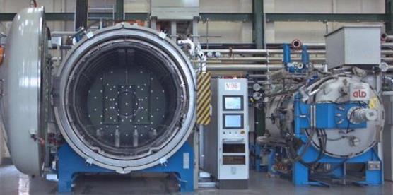
Thisistypeofmetalworkingprocessforchangingproperties of metal. It involves heating and cooling of material to extreme temperatures to achieve results of hardening or softening.Thebasicprocessesinvolvedareannealing,case hardening, tempering, carburizing, normalizing and quenching.Aftertherequireddimensions ofgearmaterial are cut, it will be sent for heat treatment to increase its strengthandtooptimizethecharacteristicsofmetal.
3.1.3. Milling
Involute gear cutter Generating involute profiles
SlittingSaws Generating deep slots andpartingoffsurfaces
CutterHobbing
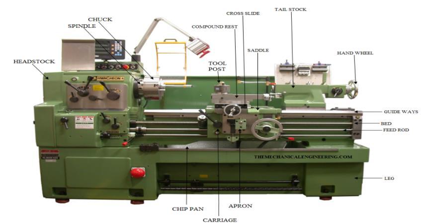
3.1.4. Turning Theseoperationsarecarriedonlathemachinewherethejob orworkpiecerotatesandthetoolmoveslinearlyonaxisof rotation.Thebasicoperationscarriedonlathemachineare turning, drilling, facing, grooving, threading, knurling, parting,chamferingandtaperturning.Inturningoperation, the excess material is removed to reduce the diameter of workpiece.While,infacingthefaceofworkpieceismadeflat orit’sdonetoreducelengthofcircularworkpiece.Knurling isdonetogenerateroughtexturedsurfaceforfunctionalor decorativepurpose.Groovingisdonetogenerategrooveon workpiece. Parting is done to cut the workpiece. Various toolsused for differentturningoperations they areSingle point cutting and turning tool, Knurling tool, Form tool, Partingtool,Chamferingtool,Formtool,DrillBitsetc.Onthe
A significant number of metals can be cut using milling operation.Mostofthedesignedpartscanbemanufactured using milling techniques. The most milling operations carried these days can be done using Vertical machining centre(VMC).Thetwotypesofmillingmachinewhichwere usedwereHorizontalmillingmachineandVerticalmilling machine.Theyrequiredlotsofeffortbyoperatortomove spindleinoppositedirectionoftherotationofcuttingwheel.
International Research Journal of Engineering and Technology (IRJET) e ISSN: 2395 0056 Volume: 09 Issue: 01 | Jan 2022 www.irjet.net p ISSN: 2395 0072 © 2022, IRJET | Impact Factor value: 7.529 | ISO 9001:2008 Certified Journal | Page363
MillingHorizontal SlabMills Requiringlargecutting offlatsurfaces
Facing,Slotting,Profile Milling
Table.1 TypesoftoolsusedinMillingoperation
Fig.3.2. VacuumHeatTreatmentMachine[6]
MillingVertical
3.1.2. Heat Treatment
Fig.3.1. BroachingTools
Rough cut endMills
SideandFace Cutters Cutting of shoulders andslots
Milling types Tools used Application
Face cuttersmilling Heavycutting
Gear Cutters
TheprincipalofTIGstatesthatnegativelychargedelectrons willmovetowardspositivepoleandionstonegativepole.As aresult,therewillbecollisionbetweenelectronsandions, whichwillgenerateheatandcausefusionofparticles.Asthe speedofelectronsandionsisveryhigh,substantialamount ofheatisgenerated.Metalslikestainlesssteel,aluminium, nickelanditsalloyscanbeeasilyweldedbyTIG.Wewilluse TIG welding to weld our chassis on which the all the componentswillbewelded
It is a type of material removal process, but the material removaliscomparativelysmallerinvolume.Thetoolused has many small cutting edges, which cut metal with high dimensionalaccuracyandgenerategoodsurfacefinish.The twotypesofgrindingmachinesusedareroughgrindingand precisiongrindingmachine. RoughGrinding isusedtoremovestockwhichisexcess.Itis carried out randomly and has little or no accuracy. For example: in casted parts, welded joints, etc. The types of roughgrindersusedarehandgrinder,benchgrinder,floor grinder,swingframegrinderandabrasivebeltgrinder. Precision Grinder it is used to obtain good surface finish withhighaccuracy.Thetypeofprecisiongrindersusedare cylindricalgrinders,internalgrinders,surfacegrinders,tool and cutter grinders. In Gear grinding, teeths of gear are grindedusingaformgrindingwheelhavingashapeofwheel saucer and it is used to grind two successive faces of the teeth.
Sheet Metal Operations
Thedifferenttypesofsheetmetaloperationsinvolvedare showninthetablegivenbelow.Formanufacturingofgear housing,wehaveusedtheoperationslikeshearing,bending and embossing. Blanking will be done on faces which will passthroughshaftsandbearings.
3.1.5. TIG (Tungsten Inert Gas) welding
3.1.6. Grinding
International Research Journal of Engineering and Technology (IRJET) e ISSN: 2395 0056 Volume: 09 Issue: 01 | Jan 2022 www.irjet.net p ISSN: 2395 0072 © 2022, IRJET | Impact Factor value: 7.529 | ISO 9001:2008 Certified Journal | Page364 lathe machine we will be performing facing and turning operationtomakethefacesofgearsflatandtomakethem dimensionally accurate. Boring is also done using Lathe machinetofixgearonshafts. Turning Operations Tools used Facing + Turning Singlepointturningtool Knurling Knurlingtool Grooving Formtool Parting Partingtool Chamfering Chamferingtool45˚ Taper Turning Formtool Drilling Drillbits Table.2 TypesoftoolsusedinTurningOperation Fig.3.3. LatheMachine
Itisatypeofelectricarcweldingprocess,thefusionoccurs between workpiece and tungsten electrode. The inert gas from nozzle is continuously sprayed on welding area to protect it against atmospheric air and prevent it from oxidation. In this process the electrode used does not get consumedasinMIG(MetalInertGasWelding)process.The tungstenelectrodeisconnectedtothenegativeterminaland workpiecetothepositive.
Fig.3.4. BenchGrinder 3.1.7. Splines generation Both external and internal splines can be generated on shafts, gears and on other parts. Splines are generated to transmitpowerfromonecomponenttoanother.Theyactas akeywayswhicharemachinedtomateparts.Theprocess involvedinmanufacturingofsplinesareBroaching,Hobbing, Millingandshaping.Theinternalsplineswillbegenerated onourgearsandontheexternalfaceofshaftstoholdthe gears. Manufacturing of Gears Operations needed Gearcuttingprocess Hobbing, Shaping, Planing, Milling Gearfinishingprocess Grinding, Shortblasting, Phosphatecoating Gear forming (non cutting)process Extrusion,PowderMetallurgy, Stamping,Casting Table.3 Manufacturingtechniquesofgears
4.
Firstly, the carriage or the buggy is made of the required dimensions mentioned in design section. It is made from squaretubesofmildsteel.ThetubesareweldedusingTIG weldingmethod.Latertherackandpinionismountedinthe holesmadeonsquaretube.Theracksandpinionassemblies aremadeofEN26HSS,Similarly,anotherrackandpinion assemblyismountedontherearendofbuggy.Thetierods areattachedattwoendsofrack,whicharemadefromEN19 Steel.Thefrontalrackconsistsofteethsontwofaces.Onone facethepinionwhichisweldedatendofsteeringcolumn rotates and on another the spur gear attached to shaft rotates.Thisspurgearsaremadeofcastiron.Theshaftor mildsteelrodhas2spurgearsfastenedonboththeends. They are attached by using internal spline on gears and externalsplinesonshaft.Behindthespurgearatotherend ofshaftthereisbevelgearattachedinasimilarwaytoshaft. Attherearendtherackhasteethsonlyononefaceonwhich spurgear(pinion) rotates whengearsare engaged.In the same way another spur gear is at the end of the shaft followedbyabevelgear.Thegeararrangementisshownin figureabove.Thewheelassemblyisattachedtotierodsto allowthemtoturn.Thepedestalbearingisusedtoholdthis mainshaftinthelocationsbetweenfrontandbacksteering.
Sheetmetaloperationsbasedoninducedstresses Assembly of components
International Research Journal of Engineering and Technology (IRJET) e ISSN: 2395 0056 Volume: 09 Issue: 01 | Jan 2022 www.irjet.net p ISSN: 2395 0072 © 2022, IRJET | Impact Factor value: 7.529 | ISO 9001:2008 Certified Journal | Page365 Table.4
ECUisfurtherconnectedtospeedsensorswhichareplaced onfourwheelsandnearsteeringcolumn.Theinputrpmis senttoECUtodecidetheswitchingactionofactuators.The whole circuit is connected by means of 12 V lead acid battery.Therearpinionisattachedtoaspring,sothatthe initial position ofit always remain tocentreafterturning. Initially,thepositionofgearsisdisengaged,whereitactsas a2WS.Inthe2WSallthegearsareindisengagedposition.
Whenthevehiclesstartmovingslowlyfirstswitchingtakes placewhereinthespurgearsonparallelshaftgetsengaged withthespurgearsonmainshaft.Whenthevehiclemoves atspeedabove60Km/hrthesecondswitchingactiontakes placewherethespurgearsingearboxaredisengagedand thebevelgearsgetengaged.Thisactionofswitchinggearsat different speeds completes the assembly of automated steeringgearboxfor4WS.
5. Prototype Cost Estimation NameComponent Specifications yntitQua Cost Rack 1.5M 50T 20PA 20FW32.5PH 2 4000 Pinion 1.5M 30T 20PA 20FW 2 Spurgear1 1.25M 60T 20PA 12.5FW 4 1200 SpurGear2 1.25M 70T 20PA 12.5FW 2 700 BevelGear1 1.5M 70GT 90PT 20PA15FW 2 700 Bevelgear2 1.5M 90GT 70PT 20PA15FW 1 900 BallBearing1 ISO 15 ABB 4820 Full 5 2200 BallBearing2 ISO 15 ABB 4912 Full 8 2500 RollerBearing ISO 15 RCR 6920 Full 4 4800 BearingPedestal SKFP20FM 3 1500 PlateAluminium 1mX1mX1mm 1 1700 Tyres(Used) 145/80R12 4 5000 Rims(Used) 4Jx12ET45 4 5200 Mild Steel CircularRod 20x20ft. 1 2200 Mild Steel Squaretube 27.5mm x 20ft. t=2mm 4 2800 Table.5 EstimatedMechanicalComponentscost EstimatedMechanicalComponentsCosts=36,600Rs NameComponent Specifications Quantity Cost ControlElectronic Unit (ECU) 1 8500 SpeedSensors 10V 14V, 1Hz 400Hz,2p/rot. 5 1000 Relay 12VSwitchDelay Module 1 200 TimerCircuit 12V Switch DigitalModule 1 600 Actuator 12 V Push Pull 2 2400 Types of Stress Operations Shear Shearing, Blanking, Piercing, andtrimming Tension Stretchforming Compression Coining,Sizing Tension and Compression Drawing,BendingandForming
Anothershaftwhichisparalleltomainshaftcontains2spur gears which are inline with the spur gears on main shaft. Other shaft on other side is perpendicular and holds the large bevel gear which can engage with other two bevel gearsonmainshaft.Behindthelargebevelgearthereisa discattachment,whilethegearsonparallelshaftisholdin fixturewhichismadeusingmildsteel.Allthisassemblyis covered using housing made of aluminium sheet that is bendedtomakehousing.Bearingsareattachedinhousing throughwhichalltheseshaftswillpass.Then,thefixtureand discisattachedbyelectro mechanicalactuatorsattachedto housing,thiswillensureengagementanddisengagementof gears. The actuators are connected to ECU which further controls relay and timer circuit to allow switching action.
[12]RajivChaudhary,R.C.Singh,“Studyof4WheelSystems to reduce turning radius and increase stability”, ICARI January2014,ISBN978 93 5156 328 0 [13]AfthabPShamsudheen,HijasBS,“Fourmodesteering systemforafourwheelvehicle”,IJARIIE Vol6Issue 32020, ISSN 2395 4396 [14] Nitish Laad, Pranav Agrawal, “Design of four wheel activesteering”,IJRAME Vol.4Issue6,June2016,ISSN2321 3051 [15]SubramanyamB,P.Bridjesh,“ManufacturingofSteering componentsforracecar”,IJMET Vol.8,Issue6,June2017, ISSN0976 6359 [16] Yonas Mitiku Degu, Defaru Thomas,“Design and manufacturing of mechanical steering system for parallel parking,zeroturningradius,minimumturningradiuswith traditionalturning’,STAR Jan March2016,ISSN2226 7522 [17]SurajBobade, RushabKumat,“Designandfabricationof MechanicalCarwiththehelpofinternalgeartoobtainzero degreerotationandstraightlinestability”,GRDJournal Vol. 2,Issue3,ISSN2455 5703 Anurag Singh, Aman Kumar Sharma, “Mechanically actuated four wheel steering system”, ICSTM May 2016, ISBN978 81 932074 8 2 SaketBhishikar,VatsalGudhka,“DesignandSimulation of4WheelSteeringSystem”,IJEIT Vol.3,Issue12,June2014, ISSN2277 3754 Nilesh G. Joshi, Hardik B., “Optimization of steering system for four wheel vehicle”, IJMPE Vol.6, Issue 8, Aug 2018,ISSN2320 2092 Dishank Bari, Ankitkumar Wahane, “Design and manufacturingofasystemtomeasuretheturningradiusof vehicle”,IJESAT Vol.4,Issue 6,ISSN2250 3676
[18]
[21]
[20]
International Research Journal of Engineering and Technology (IRJET) e ISSN: 2395 0056 Volume: 09 Issue: 01 | Jan 2022 www.irjet.net p ISSN: 2395 0072 © 2022, IRJET | Impact Factor value: 7.529 | ISO 9001:2008 Certified Journal | Page366 Solenoid Battery(Used) 12VExide 1 8000 Table.6 EstimatedElectricalComponentscost EstimatedElectronicComponentsCost 20,700Rs. EstimatedTotalPrototypeCost 57,300Rs. 6. CONCLUSIONS Inconclusion,theresearchpaperhasshownamethodology formanufacturinganddesigningofgearboxforfour wheel steering system. The new steering gear box is also automated with the help of various sensors, electronic control unit and actuators making the steering system a semi automaticone.Theturningradiusofthevehiclewas reduced from 2.14m to 1.64m, decreasing nearly 20% of turningradiusofvehicle.Manufacturingprocessesdiscussed above can be implemented to manufacture such type of gearboxes in automotive industries. The prototype cost estimationshownconcludes withtheminimum estimated riseinpricesofcarshaving2WSsystemwhenreplacedwith 4WS system. The minimum difference between 4WS cars and 2WS cars will be around 23,000 Rs. This new vehicle technologyofimplementingsteeringgearboxwillhelpthe drivers of vehicle to drive comfortably and turn their vehiclesinlessradius,thatmeansthevehiclewillbeeasyto parkinnarrowareas,andtakeaturnsathighspeeds.The designed prototype gearbox can be successfully implementedincommercialvehiclesandotherautomobiles makingsteeringsystemmoreuserfriendly. 7. WebsitesREFERENCES [1]https://mojocommerce digital files production.com [2]https://www.snnemabroach.com/broaching tool.html [3]igitsarang.com [4]Steeringsystem manuals.wibla.net [5]https://autotech786.myinstamojo.com/ [6]indiamart.com [7]https://www.custompartnet.com/ [8]https://www.youtube.com/watch?v=Z7zNcDj_YeA Books and Educational Resources [9]V.BBhandari McGrawHillEducation,“DesignofMachine Elements fourthedition”ISBN978 93 392 2112 6 [10]R.SKhurmi,J.KGupta S.Chand,“TheoryofMachines”, ISBN978 81 219 2524 2 [11]https://nptel.ac.in/
Research papers and projects
[19]