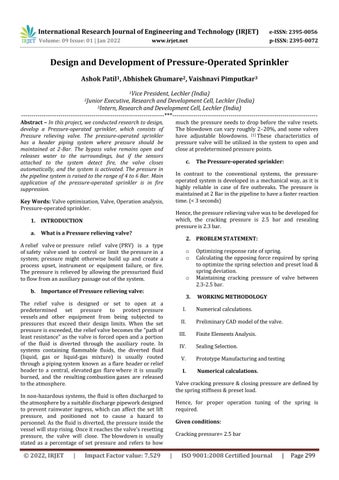
a. What is a Pressure relieving valve?
c. The Pressure-operated sprinkler: In contrast to the conventional systems, the pressure operatedsystemisdevelopedina mechanical way, asitis highly reliable in case of fire outbreaks. The pressure is maintainedat2Barinthepipelinetohaveafasterreaction time.(<3seconds) Hence,thepressurerelievingvalvewastobedevelopedfor which, the cracking pressure is 2.5 bar and resealing pressureis2.3bar.
3. WORKING METHODOLOGY
I. Numericalcalculations. II. PreliminaryCADmodelofthevalve. III. FiniteElementsAnalysis. IV. SealingSelection V. PrototypeManufacturingandtesting I. Numerical calculations. Valvecrackingpressure&closingpressureare definedby thespringstiffness&presetload. Hence, for proper operation tuning of the spring is required. Given conditions: Crackingpressure=2.5bar
b. Importance of Pressure relieving valve: The relief valve is designed or set to open at a predetermined set pressure to protectpressure vesselsand other equipment from being subjected to pressures that exceed their design limits. When the set pressureisexceeded,thereliefvalvebecomesthe"pathof leastresistance" asthe valveisforcedopenanda portion of the fluid is diverted through the auxiliary route. In systems containing flammable fluids, the diverted fluid (liquid, gas or liquid gas mixture) is usually routed through apipingsystem known as aflare headerorrelief headerto a central, elevatedgas flarewhere it is usually burned, and the resultingcombustiongases are released totheatmosphere Innon hazardoussystems,thefluidisoftendischarged to theatmospherebyasuitabledischargepipeworkdesigned to prevent rainwater ingress, which can affect the set lift pressure, and positioned not to cause a hazard to personnel.Asthefluidisdiverted,thepressureinsidethe vesselwillstoprising.Onceitreachesthevalve'sresetting pressure, the valve will close. Theblowdownis usually stated as a percentage of set pressure and refers to how much the pressure needs to drop before the valve resets. The blowdown can vary roughly 2 20%, and some valves have adjustable blowdowns. [1] These characteristics of pressure valve will be utilized in the system to open and closeatpredeterminedpressurepoints.
International Research Journal of Engineering and Technology (IRJET) e ISSN: 2395 0056 Volume: 09 Issue: 01 | Jan 2022 www.irjet.net p ISSN: 2395 0072 © 2022, IRJET | Impact Factor value: 7.529 | ISO 9001:2008 Certified Journal | Page299 Design and Development of Pressure-Operated Sprinkler Ashok Patil1 , Abhishek Ghumare2 , Vaishnavi Pimputkar3 1Vice President, Lechler (India) 2Junior Executive, Research and Development Cell, Lechler (India) 3Intern, Research and Development Cell, Lechler (India) *** Abstract In this project, we conducted research to design, develop a Pressure operated sprinkler, which consists of Pressure relieving valve The pressure operated sprinkler has a header piping system where pressure should be maintained at 2 Bar. The bypass valve remains open and releases water to the surroundings, but if the sensors attached to the system detect fire, the valve closes automatically, and the system is activated. The pressure in the pipeline system is raised to the range of 4 to 6 Bar. Main application of the pressure operated sprinkler is in fire suppression. Key Words: Valveoptimization,Valve,Operationanalysis, Pressure operatedsprinkler.
1. INTRODUCTION
2. PROBLEM STATEMENT: o Optimizingresponserateofspring. o Calculating the opposing forcerequired byspring tooptimizethespringselectionandpresetload& springdeviation. o Maintaining cracking pressure of valve between 2.3 2.5bar.
Arelief valveorpressure relief valve(PRV) is a type ofsafety valveused to control or limit thepressurein a system; pressure might otherwise build up and create a process upset, instrument or equipment failure, or fire. The pressure is relieved by allowing the pressurized fluid toflowfromanauxiliarypassageoutofthesystem.

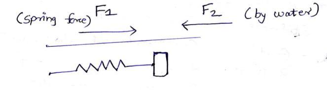
International Research Journal of Engineering and Technology (IRJET) e ISSN: 2395 0056 Volume: 09 Issue: 01 | Jan 2022 www.irjet.net p ISSN: 2395 0072 © 2022, IRJET | Impact Factor value: 7.529 | ISO 9001:2008 Certified Journal | Page300 Resealingpressure=2.3bar Hence,calculationopening&closingforcesrequired Forcrackingpressureof2.5bar, FCracking=Pcrackingxa………(1) FWhere, Cracking = Force exerted on poppet surface by water Ppressure. cracking = Cracking pressure on valve=2.5 bar = 0.25 N/mm2 A=Areaofpoppetincontactwithwater=πx(9.25)2 Puttingvaluesinequation1,weget, FCracking = 67.20 N Forresealingpressureat2.3bar, F reseal=Preseal xa….(2) Preseal=2.3bar. Puttingvaluesinequation(2),weget, F reseal = 57.7 N FCracking> K (spring stiffness) x X (deviation of spring)> Freseal Standard(3)springavailableinthemarketwasselected, No.Sr. Specification Remark 1 Springtype HelicalSpring 2 Material InconelX 750 3 Outsidediameter 18.8mm 4 Insidediameter 13.8mm 5 Springwiredia. 2.5mm 6 Freelength 53mm Asperthecalculationsgivenbelow, Springstiffnessisdefinedasfollowing, K=G.D4 /8D3n…(4) Where, G= Modules of elasticity= (for Inconel X 750) = 75.8 KN/mm2 d=wiredia.=2.5mm D=meanspringdia.=16.3mm n=No.ofactivecoils.=9 Puttingvaluesinequation.3,weget, K= 9.49 N/mm (Numericalvalue) Forceexertedbyspringunderpresetcompressionis, F=Kx FWhere,X=Force exerted by spring in opposite direction of HenceX=K=compression.springstiffness.Deviation,asperequation(3) FCracking > K (spring stiffness) x X (deviation of spring) > FReseal 67.2 > KX > 57.7 Now,takingvalueofK=9.29, ValueofXis, 7.2 > X > 6.2. As the spring stiffness differs in each material due to its properties,valueofthespringstiffnesswasmeasured. Spring stiffness of the sample spring is measured practically by loading spring under the weight and measuringdeformationinspringwhileunderload. Hence, the test was carried out where bar stock of weigh 5.19Kgwaskeptoverspring. Recordeddataasperbelow, Weightofbar=5.19weightofcollar=0.1kgkg F=ma=(5.19+0.1)x9.8=50.96N Springlength (withoutload)=53mm,spring length(with load)=46mm Deviation=53 46=7mm. F=KxX
International Research Journal of Engineering and Technology (IRJET) e ISSN: 2395 0056 Volume: 09 Issue: 01 | Jan 2022 www.irjet.net p ISSN: 2395 0072 © 2022, IRJET | Impact Factor value: 7.529 | ISO 9001:2008 Certified Journal | Page301 F = Force exerted by spring in opposite direction of 50.96Hence,X=K=compression.springstiffness.Deviation=Kx7, K= 7.28 N/mm (Actualstiffness) Hence,itisobservedthattheactualspringstiffnessisless than theoretical value. Possibly due to deviation in materialproperties. Hence, putting the actual value of spring stiffness in equation(3), FCracking > K (spring stiffness) x X (deviation of spring) > FReseal. 67.2 > KX > 57.7 As ValueK=7.28,ofXis, 9.23 > X >7.92 Hence, spring deviation to be maintained 7.9 9.2 mm to satisfytheequation3. Trialtobetakentovalidatethenumericalcalculations. II. Preliminary CAD model of the valve: Proper O ring is selected as per groove width & groove heightsuchthatsealisformedwithoutexcessiveforceson O ring and extra threading length is provided for spring tuning. III. Finite Elements Analysis: As with water hammering, and poppet material being Brass, FEA is done to check if there is any chip off during theoperation. DesignObjective SinglePoint StudyType StaticAnalysis DetectandEliminateRigidBodyModes No Material(s): Name Brass General MassDensity 8.49g/cm^3 YieldStrength 124MPa UltimateTensileStrength 338MPa Stress Young'sModulus 97GPa Poisson'sRatio 0.31ul ShearModulus 37.0229GPa PartName(s) holder2.ipt Operating conditions: Load Type Pressure Magnitude 0.700MPa Selected Face(s): Result Summary: Name Minimum Maximum Volume 15496.5mm^3 Mass 0.131565kg VonMisesStress MPa0.00308738 4.34453MPa 1st Principal Stress 1.69577MPa 1.01132MPa 3rd Principal Stress 5.67681MPa 0.299134MPa Displacement 0mm 0.000176621mm SafetyFactor 15 15
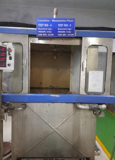
V. Prototype manufacturing and testing: Teststand: TestRig ATestrigisapieceofmachinerythatisprimarilyused to test and assess the capability and performance of components for industrial use. The term test rig is sometimes also referred to as test bay, test bench, pressure test facility and testing station but they all refer to equipment that carry out component testing.[3] Thetestrigmachineusedfortestingtheprototypehas therangeof750lpmmaximum.Itcanbearmaximum pressureuntiltherangeof5Barandmaximumusable flowrateis 500lpm. While some test rigshavepump withoutmotor,thisonecomeswithaninbuiltone.
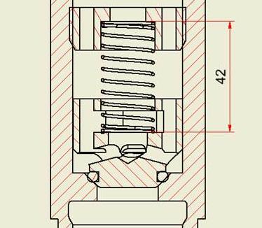
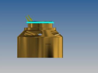
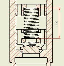
As seen in the theoretical calculations, value of the spring deviationwas9mmasitisobservedinthefigure2.(Free size: 53 mm, Spring length: 44 mm, thus, 9mm spring deviation.) But it was observed that cracking pressure of thevalvewas2.3bar
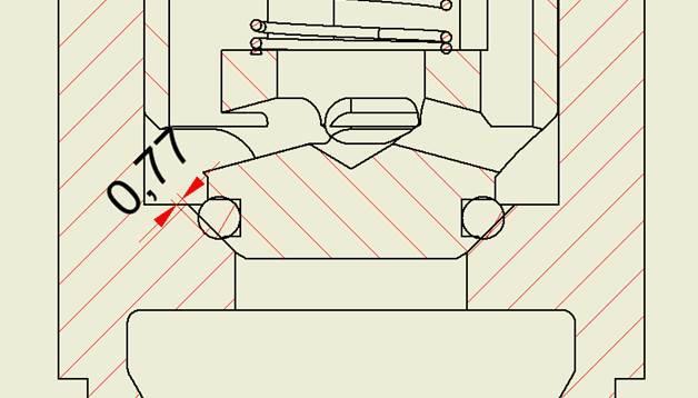
Optimumrangeofcompressionistypically8% 35% [2] As it can be observed in the design, it was ensured that metal to metal contact would be there, compression on theO ringwillbe0.7mm, whichis17%,whichliesinthe optimumrangeasmentionedabove.
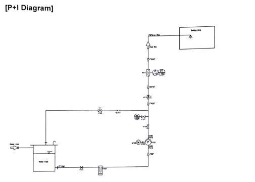
PipeandInstrumentationdiagram
Resealingpressurewasobservedtobe1.98bar, ValvewithNozzle Pressure (Bar) Flow in LPM@ 4 bar.
Water inlet on the far left side conducts water to the water tank. The water from the water tank flows to the basket filter through butterfly valve, which are usedforopeningandclosingthepipeline.Thewateris then filtered in the basket filter to supply it to the pump, which has an inbuilt motor. The pump and motor assembly pushes the water, and it passes through a non returning valve which provides a directiontothewaterandaneedlevalveinthelineto regulatetheflowofthefluid. Further, globe valve is attached which provides manualcontrolfollowedbytheflowmeter bysensing theflow.Wateristhensenttothetesterandtestsare carriedoutontheprototype.Figure2
International Research Journal of Engineering and Technology (IRJET) e ISSN: 2395 0056 Volume: 09 Issue: 01 | Jan 2022 www.irjet.net p ISSN: 2395 0072 © 2022, IRJET | Impact Factor value: 7.529 | ISO 9001:2008 Certified Journal | Page302 IV. Sealing selection:
Figure1
The pipe and instrumentation diagram of this test rig machine describes the workflow of the machine.
CutinValue 2.3 75.4 CutoutValue 1.98
5. REFERENCES [1] https://en.wikipedia.org/wiki/Relief_valve [2] sign_guidelines.cfmhttps://www.efunda.com/DesignStandards/oring/de [3] https://www.hydrotechnik.co.uk/hydraulic and hydrostatic test rigs
CutinValue 2.51 75.2 CutoutValue 2.27 ValvewithNozzle (Bar)Pressure Flow in LPM@ 4 bar. CutinValue 2.51 75.4
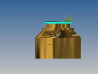
International Research Journal of Engineering and Technology (IRJET) e ISSN: 2395 0056 Volume: 09 Issue: 01 | Jan 2022 www.irjet.net p ISSN: 2395 0072 © 2022, IRJET | Impact Factor value: 7.529 | ISO 9001:2008 Certified Journal | Page303 Figure3 Value of the preset was increased to increase the preset load and 2nd trial was conducted with spring deviation of 11 Valvemmwastestedonceagaintoensureproperworking, Test parameters: Deviationinspringmaintainedat11mm Restoftheparameterswereunchanged, Observationsasperfollowing, Valvecrackingpressure:2.5 2.52Bar Valveresealpressure:2.27 2.23Bar Cyclictestwasconductedfor10cycles. Table 1: PerformanceTrialofPressureoperatedvalve ValvewithNozzle (Bar)Pressure Flow in LPM@ 4 bar. CutinValue 2.52 75.4 CutoutValue 2.25 ValvewithNozzle (Bar)Pressure Flow in LPM@ 4 bar. CutinValue 2.52 74.9 CutoutValue 2.27 ValvewithNozzle (Bar)Pressure Flow in LPM@ 4 bar. CutinValue 2.52 75.2 CutoutValue 2.26 ValvewithNozzle (Bar)Pressure Flow in LPM@ 4 bar. CutinValue 2.52 74.8 CutoutValue 2.27 ValvewithNozzle (Bar)Pressure Flow in LPM@ 4 bar. CutinValue 2.52 75.2 CutoutValue 2.26 ValvewithNozzle (Bar)Pressure Flow in LPM@ 4 bar. CutinValue 2.52 74.8
CutoutValue 2.27 ValvewithNozzle (Bar)Pressure Flow in LPM@ 4 bar.
CutoutValue 2.27 ValvewithNozzle (Bar)Pressure Flow in LPM@ 4 bar. CutinValue 2.51 74.8 CutoutValue 2.27 ValvewithNozzle (Bar)Pressure Flow in LPM@ 4 bar. CutinValue 2.51 74.8 CutoutValue 2.27 Hence,asdepictedfromtheobservationstable,cyclictests ensuredtherepeatabilityoftheperformanceofthevalve.
4. CONCLUSIONS
The check valves are the most important part of the instrumentation tube fittings. They must be designed carefullytocopewithpreciseworkingrequirements. The paper explains the various detailed operation, function and applications of relief valve with the design considerations and various materials used for the check valves. The paper also presents the thoughts on design of the check valve and analysis of the same. Spring plays mainroleinspecific crackingpressureand itisalsomore prone to failure, due to shear by applied compression loading. The cracking pressure of valve by testing is 2.3 2.5 bar respectively, which are very close to the required values.TheanalysisofcheckvalveonFEAshowsthatitis safe with the equivalent stress of 4.34 MPa and no deformation. The theoretical values and experimentation valuesshowsverysmallpercentageof error.Inthefuture scopewe May lead to optimization by using various size of relief valve.