International Research Journal of Engineering and Technology (IRJET) e-ISSN:2395-0056

Volume: 09 Issue: 11 | Nov 2022 www.irjet.net p-ISSN:2395-0072

International Research Journal of Engineering and Technology (IRJET) e-ISSN:2395-0056
Volume: 09 Issue: 11 | Nov 2022 www.irjet.net p-ISSN:2395-0072
Abstract- Dubai’s transmission power system plays a vital role in delivering optimum reliability and uninterrupted power. We therefore need to maintain the highest levels of technology,operational and cybersecurity bestpractices for alldigitalsystems.
This paper aims to provide the conceptual overview and benefits of a digitally optimized substation design The new design includes control, protection and cyber security systems supplied from different vendors from across the globe which are engineered, configured and extensively laboratory tested to ensure perfect functionality of these highly complex and challenging digital technologies. Identifying the latest technologies available and implementing these in innovative new ways has produced new designs that enhance functionalityandreliability whilst reducing large quantities of discreet components and circuitry.
At station level, virtual technologies are introduced and are embedded in two servers each of which includes all SCMS, cyber security, engineering workstation and data storage withseamlessredundancysimilartocloudcomputingserver centers.Serversareconfiguredinaclusterconfigurationwith theremoteOTdatacenteraswitnessserver.Allapplications runinadedicatedvirtualmachineandvirtualsecurityscans and records all traffic with artificial intelligence monitoring performedatthecybersecurityoperationscenter(CSOC).
At 132kV bay level, duplicate and integrated control and protection is introduced through two multifunction intelligent electronic devices (IED’s) per bay, each from a different manufacturer. All inter-bay connections are digitizedthrough
IEC61850 process bus, which are engineered to be interoperable and interchangeable between different manufacturers without the need for reconfiguration. The latestIEC61850-9-2compliantIED’sprovideenhanceddigital faultrecordingcapabilitywhichautomaticallytransmitsfault records through the IEC61850 network in the common
Comtrade file format. Fault records are automatically available at the station HMI and at the central data center. Remote access to all IED’s is provided through a secure virtual desktop application. Role based access, centralized user and password management is managed by a specialist OTsecurityteam.
Theuniquenewdesigns were developedinhouse by DEWA specialists in conjunction with specialists from the original equipment manufacturers and software developers. The digitally optimized substation (DOSS) is a completely new designfocusedondigitizationandoptimizationofallcontrol, protection, data acquisition communications and cyber securitysystems.
Thedigitizationofthousandsofcomponentsandreductionof over100kmofcopperwiringdeliverssignificantreductionin carbon footprint, reduction in building size, energy saving, cost reduction while improving the functionality and reliabilityofthetransmissionpowersystem.Thisinnovative initiativewillensurethatDEWAwillhavearguablythemost advanced substations both regionally and globally by introducingthelatestdigital technologies,optimizeddesigns inlinewiththeindustryleadingbestpractices.
Dubai Electricity & Water Authority (DEWA) was established in 1992 by His Excellency Sheikh Maktoum bin Rashid Al Maktoum with the objective to provide reliable power to residents of the Emirate of Dubai. Since its inception, DEWA has continuously invested in maintaining and upgrading the power delivery infrastructure to meet theincreasingdemandsofthegrowingEmirateofDubai.
DubaiElectricity&WaterAuthority(DEWA)PowerSystem includes Generation, Transmission and Distribution networks.Thetransmissionnetworkoperatesat400kVand 132kV voltage levels with over 350 transmission substations consisting of 400/132kV, 132/33kV and 132/11kVsites.
International Research Journal of Engineering and Technology (IRJET) e-ISSN:2395-0056
Volume: 09 Issue: 11 | Nov 2022 www.irjet.net p-ISSN:2395-0072
The new substation designs take the latest equipment and technologies, applies them to substations in new and innovativewaysthatbenefittheenvironment,DEWAandthe community.

A full digital substation by definition includes low power instrument transformers (LPIT’s) also known as nonconventionalinstrumenttransformers(NCIT’s).TheseNCIT’s are connected to merging units, which perform analogue to digital conversion, applies a time stamp in order for the sampledvaluestobetransmittedoveranethernetnetwork.
However, looking carefully at the concept of a digital substation, it is evident that since the NCIT’s are analogue devices that produce an analogue sinusoidal output, these systems are no more digital than conventional instrument transformers. The fact remains that substations transport powerwhichistheproductofvoltageandcurrentwhichare analogquantitiesbothatprimaryandatsecondarylevels.We canthereforeconcludethatthetermfulldigitalsubstationis somewhatmisleading.

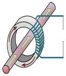
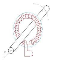
In full digital substations non-conventional instrument transformersformeasuringcurrentareeitherarogowskicoil
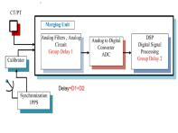
oropticsensorbothofwhichareanalogsystemsasshownin Figure1. These NCIT’s transfer analog quantities in proportion to the measured primary quantities to merging units (MU) which perform analog to digital (A to D) conversion much the same as conventional IED’s which alreadyhavebuiltinAtoDconvertersbasedon1ampinput rating. The significant different appears at the output of the merging unit which transmits the measured data through ethernet. This is where the system becomes complex since ethernetdoesnothaveadefiniteorafixeddatatransmission time.Thisisunacceptableforprotection systems,which will becomeunstableduetomeasurementmisalignment.
The merging units therefore need to time tag each sample before transmitting. Since the IED’s are sampling at about 8kHz this amounts to a very large amount of data being transmitted for the 3phases plus neutral for currents and voltages from each merging unit. This data is transmitted through the process bus which in turn has the effect of slowing the ethernet speed. The additional cost, complexity, additional components with the obvious adverse impact on reliabilitywouldlogicallybeimplementedifthereweresome significant benefits. The claimed benefit is that NCIT’s
produce a more linear and accurate measurement, which may be true if there was an identified reason why the conventionalsystemwasnotadequate.SinceprotectionIED’s have very advanced filtering and algorithms capable of maintaining optimum performance even with significant nonlinearity or saturation during faults – this advantage is negligibleinalmostallapplications.
For most applications it therefore becomes evident that the use of merging units is unwarranted and are an additional equipmentrequiredtobeusedthatreducesoverallreliability andavailabilityofthepowersystem.
MergingUnit Ethernet Switch
AnalogmA
ConventionalCT
Bothsystemsuseanalog measurementthroughanAtoD converter
Process Bus
AtoD converter isbuiltin

Fig1: Comparison of conventional CT vs Rogowski coil NCIT
Analog1A
Non-conventionalinstrumenttransformers forall substation equipment such as bushing CT, Reactor internal CT and transformer neutral CT are not available especially for applications which are immersed in oil This makes a full digitalsubstationusingallNCITsnotpossible.
InDEWAa typical132/11KVsubstationhas 71 x11kV bays whichwouldresultinalargenumberofmergingunitsanda largeamountofdataontheprocessbus.Theadditionalcost, complexity and the fact that OEM’s are unable to provide a consistentsolutionmakesthisoptionimpracticalconsidering thatthereisnobenefittothepowersystem.
A quick comparison of NCIT with conventional CTs is as shown in table below. A NCITI requires a matching merging unit which needs to be considered as part of the measuring systemwhencomparedtoaconventionalCTwhichdoesnot requireadditionalcomponentsinordertoconnecttoIED’s.It is evident that NCIT does have several disadvantages over conventional CTs in terms of mean time between failure (MTBF), performance, life expectancy etc. This is a separate
International Research Journal of Engineering and Technology (IRJET) e-ISSN:2395-0056
Volume: 09 Issue: 11 | Nov 2022 www.irjet.net p-ISSN:2395-0072
subject and the details are not covered in this paper; however,itisevidentthatuseofNCIT/sensorswithmerging unitsdoesnotofferanygreatadvantagestowardssubstation digitizationasshowninTable-1
Description
Conventional CT Vs NCIT
Conventional CT Sensor + Merging Unit (NCIT)
Life expectancy >40years 20years
Mean time between failures (MTBF) 1,506,939 500
Replacement strategy Notrequired Mayrequirenew GIS
Consequence of failure 1xprotection out
Feeder+Busbar prot.+Control out
Probability of interruption Low High
Performance Medium High
Advantage Reliability
Claimoffull digital


DEWA took the initiative to review the digital substation concept and developed an innovative digitally optimized substation(DOSS)design.Thenewdesignretainstheproven reliable conventional instrument transformers and utilizes the most practical and beneficial digital substation concepts of process & station bus. The DOSS design utilizes the latest smart technology available in intelligent electronic devices (IED’s) which allows customizing and optimizing the configuration of the control and protection systems in substations while reducing the number of auxiliary relays andcomponents Thisapproachultimatelyachievesthebestengineered solution whilst achieving higher reliability, cost reductionandlowercarbonfootprint.
ThekeyfeaturesoftheDOSSdesignare:
Consistent substation design irrespective of the contractors/OEMs
More efficient design approval process for new substationprojects
Reductionintimerequiredforprojectdesignapprovals, testing&commissioning.
Additional benefits such as reduction of maintenance cost, ease of operation and simplification of the substationdesign.
Using conventional instrument transformers ensures that protection and control systems can be refurbished in future without the risk of needing to replace instrumenttransformersorpossiblyswitchgear.
Thedigitallyoptimizedsubstationsimplifiedarchitectureis showninFigure-2.
Figure-2: Simplified DOSS Architecture
Optimization of control and protection system considered thefollowingmainaspects:
Protection & Control functions are integrated in single IntelligentElectronicDevice(IED)
Hard-wired interlocks replaced with digital signals (IEC61850GOOSEsignalsoverprocessbus).
Electromechanical relays replaced with digital functions.

ReductionoreliminationofCTs.
Integrated busbar and feeder backup protections for 11kVnetwork
IntegratedTapChangeController(AVR).
Removalof24xmeteringunitson11kV.
Elimination of external DFR devices by utilizing the inbuiltfaultrecordercapabilitiesinIEDs
International Research Journal of Engineering and Technology (IRJET) e-ISSN:2395-0056
Volume: 09 Issue: 11 | Nov 2022 www.irjet.net p-ISSN:2395-0072
Each bay shall have two independent and redundant protectionandcontrolsystems.
Two independent auxiliary DC systems for BCPU-1 & BCPU-2,toavoidcommonmodefailure.
Protection schemes engineered to produce efficient designs with minimum number of auxiliary components.
Standardization of SCADA alarm lists with reduced numberofalarmstothemastercontrolstation.


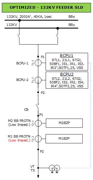
Fora typical 132kVfeeder baytheexisting conventional SS design and new digitally optimized SS design are as shown inFigure-3.
Integrated Protection,BCU, SynchCheck, VSSandDFRin bothBCPUs DigitalBusbar Protectiondoes notrequirea separateCTfor theCheckZone

The protection and control designs for a typical feeder bay in conventional and new DOSS designs are compared in Table-2.
Main-1Protection (M1FP)
Main-2Protection (M2FP)
BayControl& ProtectionUnit-1 (BCPU1)
BayControl& ProtectionUnit-2 (BCPU2)
HighImpedance Main-1Protection (M1BZP)
LowImpedance Main-2Protection (M2BZP)
LowImpedance Main-1Protection (M1BZP)

BayControlUnit (BCU) NotApplicable (Integratedto BCPU1,2and RespectiveCT core eliminated) Fault recorder DFR Busbar protection
LowImpedance Main-2Protection (M2BZP)
DOSSdesignsincludeintegratedcontrol&protectionpanels (CPP)insteadofseparateprotectionandcontrolLCCpanels. A comparison of existing and new panels are as shown in Figure-4.
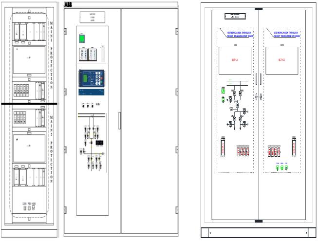
Existing132kVFeeder ProtectionPanel Existing132kVFeederLCCPanel
New132kVControl&Protection Panel(CPP)
AllProtection,BayControl,Voltage SelectionScheme,DFR&Interlocks areintegratedintonewBCPU’s withcompleteredundancy.
Figure-4: Feeder bay panels between conventional and DOSS design
International Research Journal of Engineering and Technology (IRJET) e-ISSN:2395-0056
Volume: 09 Issue: 11 | Nov 2022 www.irjet.net p-ISSN:2395-0072
Accordingly, similar optimizations are done for all 132kV and 11kV bays in the new DOSS design. As per the new BCPUandBMPfunctionality,theprotection&control IED’ s are prequalified and approved after successful laboratory testing
TheapprovedBCPU,BMPIEDsforsomeoftheapplications areasshowninbelowTable-3.
Table-3: Prequalified BCPU, BMP IEDs for DOSS SS
Voltage Level
132kV
Typical Bay Application IED Make IED Type
Feeder BCPU1/ BCPU2
132kV BusCoupler BCPU1/ BCPU2
132kV IDT Transformer BCPU1/ BCPU2
11kV
Feeder, Incomer& Capacitor Feeder BMP
Siemens 7SL87 SEL 411L
Hitachi RED670
Siemens 7SJ85 SEL 451 Hitachi REC670
Siemens 7UT85 SEL 487E
Hitachi RET670
Siemens 7SJ85 SEL 451 Hitachi REC670
InthenewDOSSdesign,theSCMSiscompletelyredesigned and introduces virtual technologies. The number of SCMS componentsaregreatlyreducedwhilstincreasingreliability and redundancy. The SCMS architecture utilized in new DOSSdesignisasshowninFigure-5.
Standardization in DOSS design achieved by preparing standarddesigndocumentsbyDEWAandincludingthemas partoftenderdocumentsforcontractor’sstrictcompliance. Thefollowingarethestandarddesigndocuments:
ControlandProtectionspecification
SCMStechnicalspecification.
DCtechnicalspecification
Meteringtechnicalspecification.
Conceptual protection single line diagrams, trip logics andcontrol&interlocklogicsforallthetypicalbays.
Control and protection panel schematic and general arrangementsdrawings
SubstationDCsystemsinglelinediagrams.
Substation DC chargers schematic and general arrangementdrawings.
Testterminalblockstandardterminalarrangements.
MasterstationSCMSsignallistwithstandardIEC61850 signaladdress.
Standard CT & VT parameters for all bays and all applications.
BCPU/ BMP IEDs specific wiring templates for each makeandapplication.
Inadditiontoabovementionedstandarddesigndocuments, pre-qualified manufacturers were also provided to the contractorstoselecttheapprovedvendors.
International Research Journal of Engineering and Technology (IRJET) e-ISSN:2395-0056
Volume: 09 Issue: 11 | Nov 2022 www.irjet.net p-ISSN:2395-0072
ApprovedIEDslist.
Approvedprotectionandcontrolcomponentlist.
Approvedenergymeterslist.
ApprovedCTandVTmanufacturerslist.
Approvedpanelmanufacturerslist.
ApprovedDCsystemmanufacturerslist
The new innovative digitally optimized substation design provides significant benefits to DEWA as a utility. The new design for 132/11kV substations includes the following advantages:
Protection & control functions are integrated into a single IED (BCPU1/2): Reduction of 15 IEDs, redundancy in control functions and 18 x control and protectionpanelsremoved.
Hard wired interlocks are replaced with peer-peer GOOSE digital signals: Over 100km of copper cabling eliminated.
All electromechanical relays replaced with digital systems:Over8000devicesremoved.
Reductioninthenumberofcurrenttransformers:Total 258unitsremoved.
Integrated busbar and feeder backup protection for 11kVnetwork
Integrated tap change controller (AVR) into BMP IEDs: Panelwith3xcontrollersremoved(digitized).
Removalof24xmeteringunitson11kV.
Integrated digital fault recorders (DFR’s): 3 x DFR panelsremoved.
Optimized SCMS system: 4 x SCMS panels, 5 x computers, 2 x monitors, 20 x network switches, 196 fiber optic cables, 4 x fiber optic patch panels, 1 x GPS clockremoved.
Virtual security, role based remote engineering access throughvirtualmachineisachieved.
The summary of removed equipment as part of the 132/11kVdesignoptimizedSSareasshowninTable-4.
Table-4: Summary of removed equipment in DOSS SS
S.No. Equipment
132kV IDT's
Remove3x132kV ProtectionPanels 3 4 132kVBus Coupler Remove1x132kV ProtectionPanel 1 5 132kVLCC
Reduce6,707x components(Aux relays,timers, terminals,mcb's, switchesetc.)
6707 6 11kVFeeder with Metering
Optimizedwith reducedCT'sand components 672
Metersremovedand CT'sformeteringare retained. 255 7 11kV Feeder without Metering
8 11kVCap Bank
ReducedCapacitor BankProtectionrelay andintegratedinto BMP. 102 9 11kV Incomer
CheckZonerelay removed,AVR functionintegrated intoBMP. 81
10 11kVBus Sections ReducedCT'sand severalcomponents digitized 59 11 11kV Busbar
RemoveHigh Impedancescheme andimplementLow ImpedanceBBPwith integrated11kV FeederBackup protection.Reduce73 xsetsofCT's
3 12 LVAC
Remove34 componentsincluding HighImpedanceREF &CT's 34 13 SCMS
SCMSpanels& components 232 14 AVR
Remove1xAVR panelsand equipment’s 4 15 DigitalFault Recorder (DFR)
Remove3xDFR panelsand equipment’s 3
Total 8198
International Research Journal of Engineering and Technology (IRJET) e-ISSN:2395-0056
Volume: 09 Issue: 11 | Nov 2022 www.irjet.net p-ISSN:2395-0072
Additionally, the new design will support DEWA’s vision andenvironmentalgoals.
The reduction in carbon emissions approximately 37 tons per year for 132/11kV substation due to annual energysavingof53MWH.
Reductioninsubstationbuildingsizeby133m2
Savingsof7millionAEDpersubstation duetoreduced equipment
The new design utilizes, control and protection panels (CPP) developed in the UAE along with local manufacturers.
The DOSS design selects the best technologies available, combines it with best design practices to achieve the industryleadingoptimizedsubstationdesign.
TheinnovativeDOSSdesignconceptcanbeimplementedin otherorganizationsglobally,whichhave the same business portfolio (electricity supply), and this will positively influence our responsibility to support the sustainable developmentgoalsandprotecttheenvironment.
[1] John bettler, Jesse Silva, Dan Morman, “Case Studies of IEC61850 Process Bus Systems Using GOOSE and Sample Values: Recent Installations and Research”, proceedings of the 74th Annual Georgia Tech Protective Relaying Conference,April-2021.
[2] Stefan Meier, Thomas Werner, “Performance considerations in digital substation applications” white paperpresentedatPACWorldUK2015.
[3] Greg Rzepka, Scott Wenke, Sarah Walling, “Choose Simplicity for a Better Digital Substation Design”, 70th Annual Conference for Protective Relay Engineers, Texas, April-2017.
[4] Qinccui Fu, Jianyun Chen, “Design of Experiment Platform for Digital Substation Based on IEC61850”, 5th InternationalConferenceonComputerScienceandNetwork Technology(ICCSNT)-2016
[5] Topolsky D.V., Topolskaya I.G., Topolsky N.D, “DevelopmentofanIntelligentMeasuringSystemforDigital Substations”, International Multi conference on Industrial EngineeringandModernTechnologies(FarEastCon)-2018.
[6]E.V.Solomin,D.V.Topolskiy,N.D.Topolskiy,“Integration of Adaptive Digital Combined Current and Voltage Transformer into Digital Substation Ethernet Grid”, International Siberian Conference on Control and Communications(SIBCON)-2015.