International Research Journal of Engineering and Technology (IRJET) e-ISSN:2395-0056

Volume: 09 Issue: 11 | Nov 2022 www.irjet.net p-ISSN:2395-0072

International Research Journal of Engineering and Technology (IRJET) e-ISSN:2395-0056
Volume: 09 Issue: 11 | Nov 2022 www.irjet.net p-ISSN:2395-0072
1B.E Mechanical Engineering (2022), Chaitanya Bharathi Institute of Technology(A)
2B.E Mechanical Engineering (2022), Chaitanya Bharathi Institute of Technology(A) ***
Abstract - This paper describes a method for designingand fabricating an Alpha Stirling enginewiththe goalofbuildinga working prototype. The Stirling cycle is a dynamic system which have one hot and one cold cylinders. Standard dimensions are used to calculate all design parameters and control tools. This type of engine has a high-volume ratio, but becomes unstable on reaching high temperature. Stirling engines convert heat energy into electricity without polluting the environment using solar energy as a primarysource. Solar energy is one of the world's fastest-growing renewableenergy sources. The ideal Stirling engine would be as efficient as a Carnot engine, so it can generate more power than normal solar panels. Stirling engine won’t release any kind of pollution into the environment. Fabricating of Stirling engine required low cost than compared to another engines. We used SolidWorks to design the engine parts with standard dimensions for specific power output. After designing, the parts were fabricated using CNC machining and surfacefinish is done to avoid friction between the parts. We calculated the theoretical power output of the engine is 0.785 kWat 300 rpm with cylinder diameter of 36mm. The theoretical efficiency is around 40%.
TheStirlingenginesworksonaclosedthermodynamiccycle as they are external heat engines, so we maintain temperaturedifferencebetweenthetwocylinderoneishot cylinderandotheriscoldcylinder.SolarStirlingengineuses solar radiation energy as external heat source for heating workingfluid(gas)toconvertthermalenergyintoelectrical energy.ThereisanidealStirlingenginethathasanefficiency of 40%, in contrast to others engines like the otto engine, which has 25% and the diesel engine, which has 35%. Stirlingengineworkbyisochoricandisothermalprocesses. Stirlingengineshavea highercapital costandareheavier thaninternalcombustionengines;however,theyrequirea lower maintenance cost. It is more efficient than other engines, but controlling it at high temperatures can be challenging.
• B. Kongtragool Et Al, 2003 [1] reviewed on solar Stirling engine and low temperature differentialStirlingenginetofindfeasibledesign
and workable solar-powered low temperature Stirling engine. This paper results shown low temperatureairaregivenmoreenergy.
• Krissadang Sookramoon Et Al, 2022 [2] describes in paper about using of biomass incineration to heat Stirling engine to produce electricpower.
• K.G. Maheswaran Et Al, 2017 [3] providesan explanationofhowabetatypeStirlingengineis constructed and they are external combustion enginesthatrunonStirlingcycles.Theyuseheat sources such as solar energy and agricultural wastelikepaddystraw,sugarcaneleaves,wheat stalk, groundnut shell, coconut husk, etc. The efficiencyoftheseenginesiscomparabletothe theoretical Carnot efficiency, making them suitableforstationarypowergeneration.
• K. Dinesh Et Al, 2014 [4] describeshowlowcostStirlingenginescanbebuiltandutilizedfor green energy application, including theoretical background,variousdesignsandparameters.
• Mohamed Abbas Et Al, 2008 [5] proposed thermal analysis of Stirling engine using parabolic concentrator in paper. This paper shows various energy loses that engine does whenconvertingheatintoelectricalenergy.
• Muhammad Hassan Et Al, 2021 [6] paper showcasesthatusingCADtools,thedesignand fabricationofa 90-degreealpha Stirling engine wereperformed,andthepoweroutputsfromthe Stirlingenginewereanalyzedateverydifferent temperature. At various points, external heat input was increased to observe the engine’s stability.
• Najafi. G Et Al, 2015 [7] paperdescribesabout design of gamma Stirling engine and using biomassenergyasheatsourceoftheengine.This shows gamma Stirling engine behavior at differenttemperatures.
• Snyman. H Et Al, 2008 [8] publishedpaperon designanalysisofStirlingengine,madeattempts tocreatenewdesignofenginewhicharefeasible, lowcostandproducesmorepower.
International Research Journal of Engineering and Technology (IRJET) e-ISSN:2395-0056
Volume: 09 Issue: 11 | Nov 2022 www.irjet.net p-ISSN:2395-0072
• Vishal Gehlot Et Al, 2014 [9] discussed an alphaStirlingengineprototypeisbuiltwithan emphasis on developing a new approach to development and fabrication. For maintaining controlofdynamicsystems,theStirlingcycleis recastinthispaper.
• Yaseen H. Mahmood Et Al, 2018 [10] this paper investigated the properties of Gamma Stirling engines produced using low-cost materials, and their efficiency in relation to temperaturesandpressure.
Manyresearchersinthepasthadperformedexperimentson the Stirling engine and proposed design adjustments and fabricationsmethods.MostofthemhaveanalyzedStirling engines in Ansys, but we, in this paper, are designing and fabricatingStirlingengineswithdifferentdesigndimensions
Most researchers have made studies on beta and gamma Stirlingengines.Here,wearestudyingtherangeofoutput electricity for various inputs of temperatures to an alpha Stirling engine. i.e., when the temperature parameter is varied,electricityoutputattheoutletisnoted.
In the present chapter the various components were designedtofabricatethepartsandhasbeendiscussedalong with their specifications and the working process of the prototype has also been discussed. Parts were designed usingSolidWorks.
Design of Parts: We designed 23 parts of Stirling engine andsomeofthemare
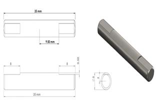
1.CrankShaft:Fig-1showsthedesignviewofthecrankshaft with length 35mm and diameter 5mm. crank shaft is responsible for converting a linear motion to a rotational motion.
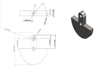
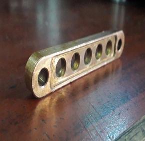
Fig-2: CounterWeightsA&B
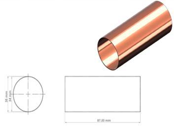
3.Cylinder:Fig-3showsthedesignviewofthecylinder.Here theairiscompressedandexpanded.
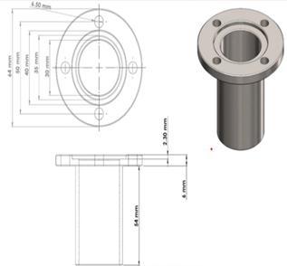
Fig-3: Cylinder
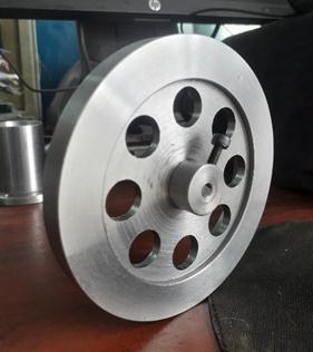
4. Flywheel: Fig-4 shows the design view of the flywheel. Flywheel is a circular disc which rotates when shaft and counterweightsrotates.Flywheelisfixedtodeliverypower fromanenginetomachine.
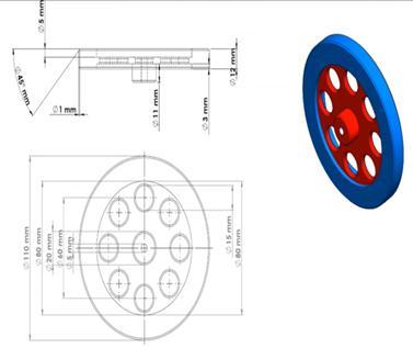
Fig-1:CrankShaft
2.CounterWeight-AandCounterWeight-B:Fig-2showsthe designviewofthecounterweight-Aandcounterweight-B. Counter weights are used for applying an opposite force, providesbalanceandstabilityofamechanicalsystem.
Fig-4: Flywheel
5.Piston:Fig-5showsthedesignviewofpistonwhichhas diameterof30mm.Pistonisusedtocompresstheairinside thecylinderandtransferenergy.
International Research Journal of Engineering and Technology (IRJET) e-ISSN:2395-0056
Volume: 09 Issue: 11 | Nov 2022 www.irjet.net p-ISSN:2395-0072
Fig-5: Piston
6. CrossHead:Fig-6showsthedesignviewofcrosshead. Cross head is a mechanism used as part of slider-crank linkagesoflongreciprocatingenginestoeliminatesideways pressureonthepiston.
Fig-8: HeatExchangerPistonTube
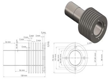
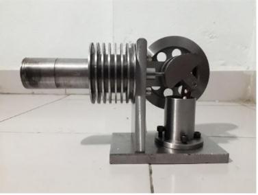
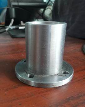
9. HeatExchangeCylinder:Fig-9showsthedesignview of heat exchange cylinder. The cylinder has fins aroundittoexchangeheat.
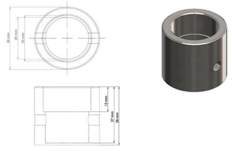
Fig-9:HeatExchangerCylinder
Fig-6: CrossHead
7. Crank Rod: Fig-7 shows the design view of crank rod. Crank rod is a part of piston engine which connects the pistontothecrankshaft.Ittransferstheforceofexpanded airtocrankshaftviaapiston.
Fabrication:
Ourprojectinvolvedthedesignofa90-degreeAlpha StirlingengineusingSolidWorkssoftware,andallpartswere designed in line with standard dimensions to fit together. TheenginepartsweremanufacturedutilizingCNCMachine techniquesaftertheyweredesignedusingoperationssuch asMachining,Milling,Lathe,Cutting,etc.Inordertoachieve good heat transfer, corrosion resistance and high ductile nature,wefoundcopperasanidealmaterialforengineparts likeheatexchangerpistonhead,crankrodandpistontube. Duringfabrication,restofthepartswereconstructedusing mildsteelsinceitisinexpensiveandweldable.Eachholewas drilled with a drill machine, and the internal thread was dyedbyhandusinganiron.Asurfacefinishimprovement was achieved by treating all parts with emery paper followingfabrication.
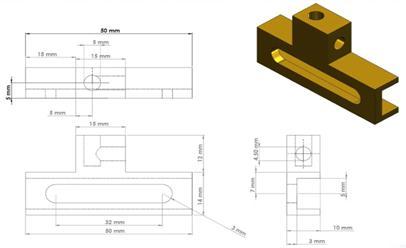
Fig-7: CrankRod
8. HeatExchangerPistonTube:Fig-8showsthedesignview oftheheatexchangepistontubewithdiameter35mmand length87.50mm.Thispistontubeexchangeheatfromone bodytoanother.
Accordingtothestandarddimensionsforenginedesign,the theoretical calculations were done before fabrication in order to determine how much power the Stirling engine wouldproduce.Asasolarparabolictroughforconcentrating solar energy was unavailable, we had to calculate power output with theoretical calculations and test the engine theoretically.
International Research Journal of Engineering and Technology (IRJET) e-ISSN:2395-0056
Volume: 09 Issue: 11 | Nov 2022 www.irjet.net p-ISSN:2395-0072
● Anenginestartswhenanexternalheatsource,such as solar energy, is provided at the end of a hot cylinder.
● Stirling engine utilizes gas as a working fluid. As whentheexternalheatsourcewasactivated,heat transfer increased to the hot cylinder, which increased the temperature of the gas molecules. Duringtheheatingprocess,gasmolecules expand insidethehotcylinderasthetemperaturerises
● Byexpandingthegas,thepistonispushedawayby thepressure,whichstartstheflywheelinmotion.
● The power piston is linked with crank shaft and displacer piston is connected with crankshaft. As crankshaftmovesthedisplacerpistondrivestocold cylinder.
● Displacer piston movement causes gas to move fromacoldcylindertoahotcylinderandviceversa.
● Through the gas exchange tube, expanded gas or heatedgasmoleculesmovefromthehotcylinderto the cold cylinder. Cooling the hot gas is accomplishedbythefinsinacoldcylinder.
● When the gas has been cooled, the piston compresses it in the cold cylinder, allowing it to movetothehotcylinder,wherethecyclerepeats. This causes the flywheel to rotate through the motionofpistonexpansionandcompression.
● Aflywheelisattachedtothemotorwhichrotatesto generate the electro flux and to produce the electricity.
International Research Journal of Engineering and Technology (IRJET) e-ISSN:2395-0056
Volume: 09 Issue: 11 | Nov 2022 www.irjet.net p-ISSN:2395-0072
V₁=Swept+Clearance
V₁=129.747×10⁻⁶ m³+6.487×10⁻⁶ m³ =136.234×10⁻⁶ m3
▪ Compressionratio
r=V₁÷V₂ =(136.234×10⁻⁶ ÷6.487×10⁻⁶) =21.001
▪
1-2isentropicprocess
T₂÷T₁=(V₁÷V₂) ﻻ-1 =(136.234×10⁻⁶ ÷6.487×10⁻⁶)1.4-1 =1057K
Accordingtoidealgasequation,P₁×V₁=m×R×T₁
Massofair(m)=0.001kg, Temperatureofair=313K P₁×136.234×10-6 =0.00159×0.287×313 P₁=0.659×10⁶kPa
P₂÷P₁=(1÷rﻻ) P₂=1÷(211.4)×(0.659×10⁶) =9.284×10⁶Pa
▪
2-3ConstantVolumeProcess
V₃=V₂ P₃×V₃=m×r×T₃
P₃×6.487×10-6=0.001×0.287×500
SupplyHeattemperature(T₃),assumeT₃=500k P₃=22.12×10⁶Pa
▪ Heatsupplied=m×Cv ×(T₂-T₃) =0.001×0.707×(10547-500) =0.39kJ/kg
▪
3-4isentropicprocessP₃÷P₄=rﻻ P₄=22.12×10⁶÷211.4 P₄=31.16×10⁴
▪
4-1ConstantvolumeprocessT₄÷T₁=P₄÷P₁
T4 =31.16×104 ×313÷(0.659×10⁶)
T4 =147.99K
▪
HeatRejected=m×Cv ×(T₁-T₄) =0.001×0.707×(313–147.9) =0.11kJ/kg
▪
Workdone=HeatSupplied–HeatRejected =0.39-0.11=0.28kJ/kg
▪
%Efficiency=(workdone/Heatsupplied) =(0.28÷0.39)×100%=71.7%
Performancecalculation
▪
1) Area=π×D×L =3.14×0.036×0.124 =0.014m2
2) Force=Pressure×Area Assume,P=1bar Force=1×105 ×0.014 =1.4kN
3) Torque=Force×Radius Radiusofflywheel=18mm =0.018m Torque=1.4×0.018 =0.025kN-m
4) Power=(2π×N×T)÷60KW =(2π×300×0.025)÷60KW =0.785kW
Therefore, Power generated from heat supply 500K with cylinderdiameter36mmis0.785kw.
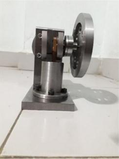
Theresultsobtainedfromthetheoreticalcalculationsofthe solar Stirling engine are discussed in this chapter. The Stirling engine wasdesignedin SolidWorkswithassumed dimensions. The designed parts were fabricated by performing CNC machining, CNC turning, drilling, wire cutting.Thetheoreticalcalculationstofindthepoweroutput fromspecificheatsupplywasperformedassumingtheheat supply as 500K with our cylinder diameter of 36mm. The theoreticalpoweroutputis0.785kWat300rpm.Becauseof fabricationdifficultieswhile machiningtheStirling engine was not performing. An attempt was made to design and fabricatetheStirlingenginewheredesignoftheenginewent wellbut,duetofabricationerrorstheengineisnotworking.
The following conclusions can be derived from the design andfabrication:
International Research Journal of Engineering and Technology (IRJET) e-ISSN:2395-0056
Volume: 09 Issue: 11 | Nov 2022 www.irjet.net p-ISSN:2395-0072
● The design of the Stirling engine provides the necessary data for the comparison of several aspectsoftheStirling-cycleengine.
● The Stirling engine parts were fabricated accordingtodimensionsinCNCmachines.
● Thetheoreticalefficiencyismorethan70%for respectivesuppliedheat.
[1] B.Kongtragool,Areviewofsolar-poweredStirling engines and low temperature differential Stirling engines,2003,Vol.7,pp.131–154.
[2] Krissadang Sookramoon, Updraft gasifier-Stirling engine biomass incineration system power generation,2022,vol19,pp.1-11.
[3] K. G. Maheswaran, Design and Manufacturing of BetaStirlingengine,2017,vol6,pp.1-9.
[4] K. Dinesh, Design and Fabrication of low-cost Stirlingengine,2014,vol3,pp.75-78.
[5] MohamedAbbas,ThermalperformancesofStirling enginesolardriven,2008,vol8,pp.1-10.
[6] Muhammad Hassan, Design and Fabrication of Stirling engine for solar power application, 2021, vol143,pp.1-7.
[7] Najafi. G, Design, Fabrication and Evaluation of Gamma typeStirlingengine, 2015,vol 7,pp.137143.
[8] Snyman. H, Design analysis methods for Stirling engines,2008,vol19,pp.4-19.
[9] Vishal Gehlot, Development and Fabrication of Stirlingengine,2014,vol11,pp.69-71.
[10] YaseenH.Mahmood,FabricationofStirlingengine andstudyofitscharacteristics,2018,vol8,pp.96100.