International Research Journal of Engineering and Technology (IRJET) e-ISSN:2395-0056

Volume: 09 Issue: 10 | Oct 2022 www.irjet.net p-ISSN:2395-0072

International Research Journal of Engineering and Technology (IRJET) e-ISSN:2395-0056
Volume: 09 Issue: 10 | Oct 2022 www.irjet.net p-ISSN:2395-0072
Prasanna P N1 , Dr. Prakash P.2 , Mr. Suhas R.3 .
1Prasanna P N, M. Tech Student, Department of Construction Technology & Management, Dayananda Sagar College of Engineering, Bangalore, Karnataka, India
2Dr. Prakash P., Professor & HOD, Department of Construction Technology & Management, Dayananda Sagar College of Engineering, Bangalore, Karnataka, India.
3Mr. Suhas R., Assistant Professor, School of Civil Engineering., REVA University, Bangalore, Karnataka, India. ***
Abstract - Roads have a significant social benefit and are essentialto development andeconomicsuccess.Fora nation to expand and prosper, roads are essential. As more locations become accessible mainly with roads, social and economic development improves. The three main components of geometric design are cross-section, horizontal alignment, and vertical alignment. Since ancient times,transportation hasbeenan issue. Ithasalsoseenalot of advancements. Highways were constructed to facilitate convenient travel, allowing people to get from one location toanotherquicklyandconveniently.
The creation of the road alignment, the charting of the alignment profile using bearings or co-ordinates (easting and northing), stations, and elevations of points along the proposed route, the calculation of sight distances, radii of horizontal curves, and lengths of vertical curves, the computation of earthwork quantities, and numerous other studies and calculations are all part of the process of designing roadways. These calculations are made in order to determine the best alignment while meeting design criteria. Geometric design is incredibly laborious, timeconsuming, and prone to costly mistakes when done manually. The use of computer software for designing roadway geometry is in demand right now. The software is extremely precise and offer significant time and effort savings. This study uses both AutoCAD Civil 3D and MX ROAD software to present a complete geometric design of a typical roadway. This saves time and money by enabling the 3Dvisualizationofthedesign.
Keywords: (AutoCAD Civil 3D, MX ROAD, Horizontal alignment, Vertical profile, Surface analysis, Alignment design)
In the last ten years, India's economy has risen tremendously, and transportation has had a big part in thatprogress.Theroadnetwork isthefoundation forany developing nation's continuous growth. A model that directs the designer to produce the most efficient design
with high precision requirements is required due to the rapid expansion in road infrastructure and the resulting necessity, which in turn results in time, money, and material cost savings. There are several programmes that are utilised for designing highways thanks to the most recent developmentsin computertechnology.Nova Point, Civil3D,AutoCivil,MXROAD,EaglePoint,andEartharein thelist.
Road geometric design can be split into three basic components: horizontal alignment, vertical alignment and cross section. These components combined together to createahighway'sthree-dimensionallayout.
i. Thehorizontal alignmentof a highwaydefinesits location and orientation in plan-view. Tangents (straight sections), circular curves, and spiral transitionsbetweentangentsandcurvesmakeup itsthreegeometriccomponents.
ii. Theverticalalignment(orroadwayprofile)isthe longitudinal section of the road, comprising such geometric elements as crest and sag curves, and the gradients (straight grade lines) connecting them.
iii. Theroadwaycrosssectionshowsthepositionand numberofvehicleandbicyclelanesandsidewalks alongwiththeircrossslopes;shoulders,drainage ditches,etc.
Inordertomakeroadgeometricdesignaccessibletocivil engineering experts working in developing countries, it must be shown how geometrical design may be carried out accurately and quickly. This study compares the geometric design of highways using MX ROAD and AutoCADCivil3D.
1.1 AutoCAD Civil 3D:
Autodesk Civil 3D software is a civil engineering design and documentation solution. Building Information Modelling (BIM) workflows are supported on a range of civil infrastructure project types, including roads and highways, land development, trains, airports, and water.
International Research Journal of Engineering and Technology (IRJET) e-ISSN:2395-0056
Volume: 09 Issue: 10 | Oct 2022 www.irjet.net p-ISSN:2395-0072
Civil 3D aids in the improvement of project delivery, the maintenance of more consistent data and processes, and the quick response to project changes. Additionally, users can use specialized tools and customizable design standards to speed up time-consuming operations including intersection, roundabout, and corridor design, parcellayout,pipelines,andgrading.
MX ROAD is a software application for the Civil Engineering and associated industries, with the primary market being that of road design. In 1996, the UK-based BentleySystemcompanydevelopedthissoftware,thathas now been updated as required. It is an excellent stringbasedmodellingtoolthatmakesitpossibletoquicklyand accuratelyconstructallkindsofroadways.Civilengineers, designers, surveyors, and system designers can all use a single engineering application to access 3D modelling, constructiondrivenengineering,andotheranalysis.
i. Comparative study of geometric design of road usingAutoCADCivil3DandMXROADSoftware.
ii. To upgrade or to improve the geometric features usingbothAutoCADCivil3DandMXROAD.
iii. Reduce the cost of road development and it’s designing.
iv. Toimprovetheroadlifebyefficientdesign.
v. Designing effective vertical and horizontal alignment.
vi. Designingofsuperelevation.
vii. Designingextrawideningwhereverrequired.
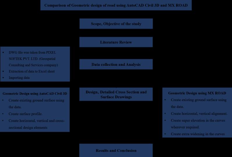
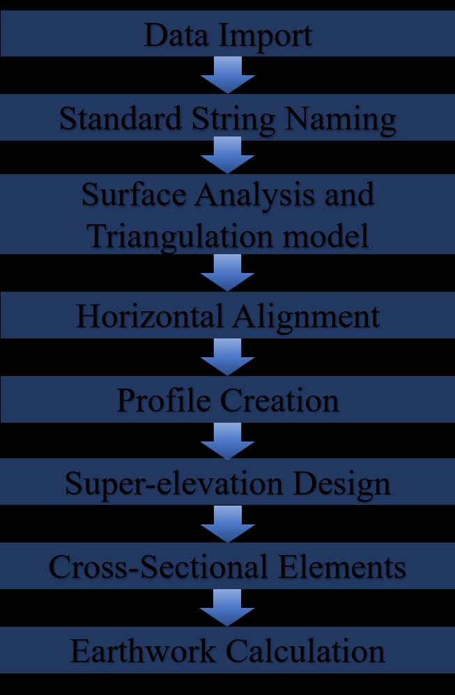
The work execution procedure is described in the flowchart Thestepsadoptedarewelldetailedinthefigure 1. The collected point data is then used for geometric design and analysis in the AutoCAD Civil 3D software and MXROADsoftware.
Chart-1: FlowchartofMethodology.
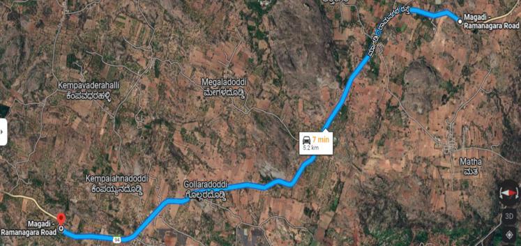
Fig-1: GoogleMapImageofTheProjectLocation.
This project involves upgrading the SH-94 from intermediate to two lanes between Chikka-Sulikere to Hanchikuppe which lies in between Ramanagara-Magadi RoadincludingCH55.0kmandCH60.2km.
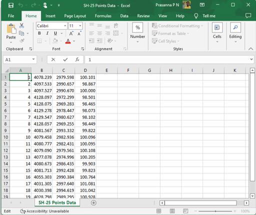
Thedata for thisstudy wasgatheredfromPIXEL and was made up of survey data of the current ground surface in .dwg (drawing) format. The study's point data was then extracted and saved in .csv (comma-separated values) formatusingtheMicrosoftExcelsoftware.Thispointdata containsthecoordinatesX,Y,andZ.(i.e.,Northing,Easting and Reduced Level). The input was in PNEZ format i.e., Points,Northing,Easting,andElevation.
International Research Journal of Engineering and Technology (IRJET) e-ISSN:2395-0056
Volume: 09 Issue: 10 | Oct 2022 www.irjet.net p-ISSN:2395-0072
2.4.1 Procedure in AutoCAD Civil 3D:
a. ImportsurveydatafromPNEZfile. b. Createexistingsurface c. MarkPolylineonexitingcenterlineofroad d. Designedaccordingtodesignproposedalignment in design-based criteria selected in civil 3d similarlymanuallycheckedfromIRC:38-1988for transition length for different speed, speed curve radii.
e. Generateexistingprofilebysurface
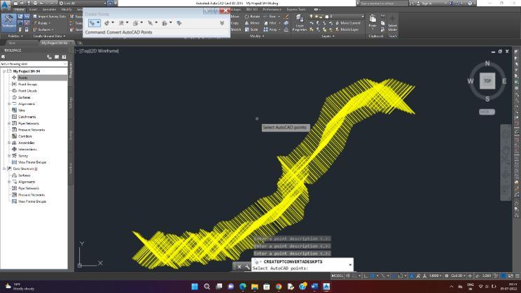
Fig-2: PointDatainPNEZformat.
i. Design speed: 50km/h – 40kmp/h (project locationfallsunderhillyterrain)
ii. Numberoflanes:2
iii. Totalwidthofroadway:8.8m
iv. WidthofCarriageway:7m
v. WidthofShoulder:1m
vi. Horizontalcurveradius:80m(Rulingminimum)
vii. SuperElevation:7%(Maximum)
viii. Minimumlengthofverticalcurves:30m ix. Rulinggradient:5%(Maximum)
x. Limitinggradient:6%(Maximum)
xi. SSD(StoppingSightDistance):60m
xii. ISD(IntermediateSightDistance):120m
xiii. OSD(OvertakingSightDistance):235m
f. Create road top level considering hydraulic calculation at structures by profile creation tools, primarilybyPolyline.
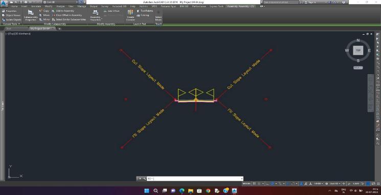
g. Create assembly is an arrangement of crosssectionfeaturesfoundonaroadway.Itrepresents a typical section of the corridor that positions an alignmentandaprofile.
h. Create an assembly using subassembly for crosssection elements such as lanes, shoulders, and crossslopes.
i. Generate a corridor which in itself is a crosssectional, horizontal design element of the 3D modelusedforcuttingandfillingcalculations. j. Generatequantityreport.
Chart-2: FlowchartofDesignProcedureusingAutoCAD Civil3D.
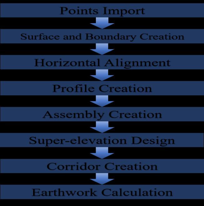
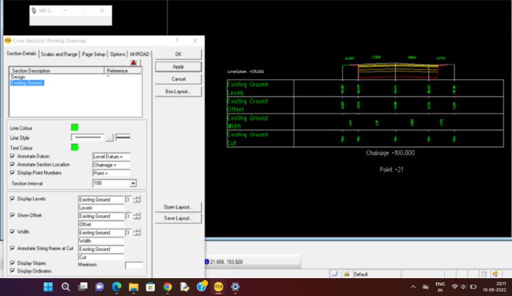
Fig-6:
International Research Journal of Engineering and Technology (IRJET) e-ISSN:2395-0056
Volume: 09 Issue: 10 | Oct 2022 www.irjet.net p-ISSN:2395-0072
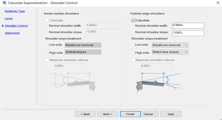
Fig-8: DesignofSuperElevationwithShoulderControlin Civil3D.
2.4.2 Corridor Creation:
Applying an assembly along the vertical and horizontal path established by the alignment and profile's combined information results in the creation of a corridor. Targets aresetfordaylightinginordertofinishthecorridor.
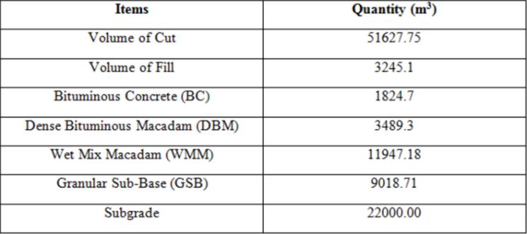
2.4.3 Earth work Calculation:
The earthwork needed for a project can be quickly calculatedowingtoafunctioninAutoCADCivil3D
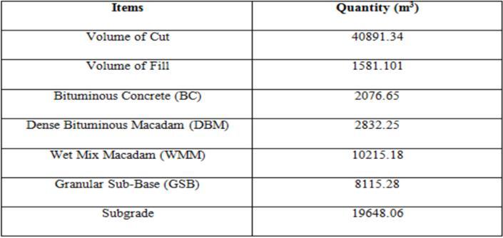
Table-1: EarthworkVolumeReportGeneratedinCivil3D.
Fig-7:
International Research Journal of Engineering and Technology (IRJET) e-ISSN:2395-0056
Volume: 09 Issue: 10 | Oct 2022 www.irjet.net p-ISSN:2395-0072
Chart-3: FlowchartofDesignProcedureusingAutoCAD Civil3D.
a. ImportsurveydatafromPNEZfile.
b. Naming strings according to MX SNC i.e., MX StandardStringNamingConvention.
c. Surface Analysis and Triangulation modeling accordingtoIRCstandards.
d. Designedinaccordancewithdesign-basedcriteria chosenincivil3danddesign-proposedalignment, with human verification of IRC: 38-1988 for transition length for various speeds and speed curveradii.
e. Horizontal Alignment was designed according to IRC: 38-1988, “Design of Horizontal Curves for HighwayandDesignTables”.
f. Vertical Alignment is designed according to IRC: SP:23-1993-“VerticalCurvesforHighways”.
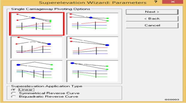
g. Designofsuper-elevation.
h. CreationofCross-sectionalselements.
i. GenerationofEarthworkVolumeReport.
Fig-10: AnalyzedsurfaceandTriangulationModelCreated usingMXROAD.
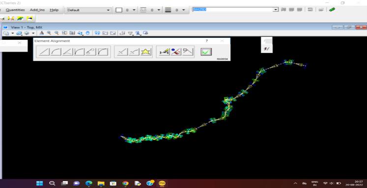
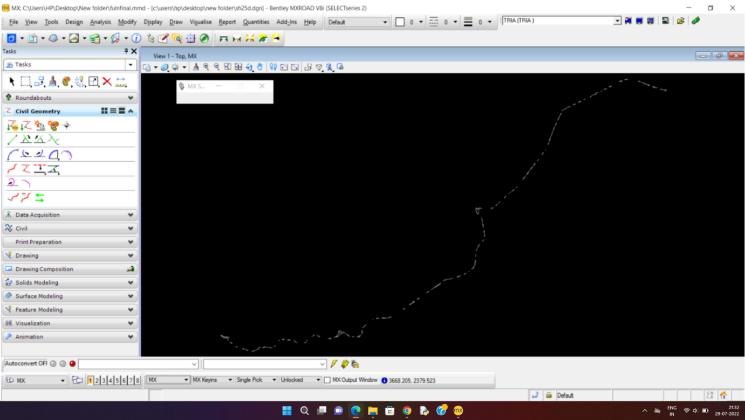
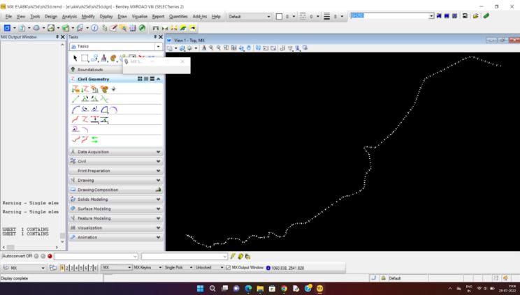
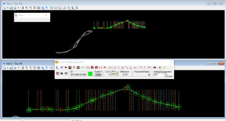
Fig-11: HorizontalAlignmentCreatedinMXROADusing ElementMethod.
International Research Journal of Engineering and Technology (IRJET) e-ISSN:2395-0056
Volume: 09 Issue: 10 | Oct 2022 www.irjet.net p-ISSN:2395-0072
3.1 Comparison of AutoCAD Civil 3D an MXROAD:
1. Users of the AutoCAD Civil 3D software can only make changes to those particular items that are impactedbymodificationstoobjectstyles,command parameters,anddesignlabels.Model-basedsoftware is created by MXROAD; object-oriented software is not. It is dependent on a background-developed designdatabase.Tomodifydesigndata,thewholeset ofinstructionsforrecreatingthemodelanddatabase files must be executed once more. The writing must thenberevisedaswell.
2. It is extremely difficult for a non-expert user to comprehend the meaning of existing strings and follow the convention for naming new strings because the use of input files for collaboration in MXROAD software necessitates string naming rules withstrictcharactercountlimits.
3. String name rules with strict character count restrictions are required for input files used for collaboration in MXROAD software, making it extremely difficult for non-expert users to comprehend the meaning of existing strings and followtheconventionfornamingnewstrings.
4. AutoCAD Civil 3D software is driven by styles because objects are managed by collections of parametersthatarebundledinastyle.Civil3Doffers a variety of regionally-conforming styles in addition tointernationaldesigns.
5. To handle any horizontal alignment geometry task, MXROAD software includes a robust collection of alignment design tools. For flexibility, it employs the fixed, free, and floating element Design techniques. By using a single set of tools for both creating and altering alignments, Civil 3D achieves this. The user uses MXROAD can see collections of connected strings that describe various pavement layers, sidewalks, benches, ditches, medians, and other features that must be kept up with and coordinated with design modifications to the master alignment anditssinglecorrespondingprofilegeometry.
6. For modelling roads, Autodesk Civil 3D employs a designobject.Thisobjectisknownasacorridorsince mostCivil3Dobjectsarebuiltasgenericengineering designobjectsthatmaybeutilizedforanypurpose.A corridor can be used to model any geometry that, in general,followsabaselineoralignment.
International Research Journal of Engineering and Technology (IRJET) e-ISSN:2395-0056
Volume: 09 Issue: 10 | Oct 2022 www.irjet.net p-ISSN:2395-0072
Table-3: ComparisonofEarthworkVolumesGenerated UsingBothSoftware.
Items Earthwork volume (m3) using AutoCAD Civil3D
Earthwork volume (m3) using MXROAD
Subgrade 19648.06 22000.00 GranularSubBase(GSB) 8115.28 9081.71 WetMix Macadam (WMM)
[5] Planning, Designing and Proposed a Flyover Road Using AutoCAD Civil 3D Software - Shivam Pandey, Er. Atul,YogeshBajpai.
[6] IRC:73-1980, “Geometric Design Standards for Rural (Non-Urban)Highways”.
[7]IRC:SP:23,“VerticalcurvesForHighways”.
[8] IRC: 38-1988, “Design of Horizontal Curves for HighwayandDesignTables”.
2832.25 3489.30
10215.18 11947.18 Dense Bituminous Macadam (DBM)
3.2 Conclusion:
1. AutoCAD civil 3D is thought to be quite helpful andalsouser-friendly.
2. According to IRC, AASHTO and the highway geometrics were also taken into consideration as safetymeasures.
3. It produced horizontal alignment, created a vertical profile, and permitted for the establishmentofcross-segment.
4. Roadwideningathorizontalgeometryandsuper elevationshouldbeplannedcarefully.
5. Everycurvethatisplottedintheprojectcomplies withtheIRCStandard.
[1] Upgradation of Geometric Design of NH163 (UppalNarapally) For Reduction in Traffic Congestion Based on Microscopic Traffic Simulation Model - Abida Mohammed Anwar,MirIqbalFaheemandMd.FaisalKhan
[2] Study of Geometric Design, hydraulic and hydrology forHighways UsingCivil 3DSoftware- ACaseStudy - Anil KumarK.S

[3] Design of Sub-Arterial Urban Road Using MX ROAD Software - Ali Asharf, Nishant Singh, Yashraj Shrivastava andJSVishwas.
[4] Up Gradation of Geometric Design of Sh-131(Ch. 9.35km-15.575km) Using MX ROAD Software - Ashok Kumar, Dhananj A S, Agarwal Alkesh, Badage Ganesh ChavanBhagatsinh,DevkarAnilandKadamShubham
Prasanna P. N., M.Tech Student, Department of Construction Technology & Management, Dayananda Sagar College of Engineering, Bengaluru,Karnataka,India

Dr. Prakash P., Professor and Head of Department of Construction Technology & Management, Dayananda Sagar College of Engineering, Bengaluru. Mr. Suhas R.,SchoolofCivil Engineering,REVAUniversity, Bengaluru.