Keywords White balance segmentation, Hue Saturation value,Contrastenhancement,regiondivision,atmospheric light,iterativedehazingalgorithm.
Animagewhichiscapturedthroughasmartphoneora digitalcamera experiencesbadweather.Foranimage,it’s visibility and contrast indicates the quality of the image. Although, the images which are captured outside are affected by low visibility and low contrast precisely in a hazyweather(Wang). Gettingridofhazeisaproductivecourseofactionsinceit can bring back an understandable image with high visibility. For that reason, it is required to establish a structured dehazing method to apply on the images obtained from digital cameras, outdoor security cameras andsmartphones.
The contrast enhancement approach presented in this paperinvolvesthreeprocedures.Firstinvertingtheimage, second,applyingdehazingalgorithm,andfinally,inverting the dehazed image to get an enhanced image. The experimental results reveals that the proposed enhancement method successfully and productively improves the quality and enhances the image and makes theimagefeaturesstandoutmoreclearly.
Images captured through mobile devices often suffer from poor quality due to poor weather conditions. Especially in hazy weather, observed images lose clarity as well as they are prone to color shifts. In this paper, a novel dehazing method for color accuracy is presented which effectively removes the haze. In the first phase, based on white balance, region division is performed, in the second phase, the local atmospheric light is estimated, and, in the third phase, an iterative haze removal algorithm is developed to make the image free from haze. This paper also presents a contrast enhancement method for the images taken in dark, which are low light intensity images. It involves the following three procedures. First phase involves inverting the image, second phase involves applying dehazing algorithm and the third phase involves inverting the dehazed image to get an enhanced image. Experimental results validates that the proposed dehazing method and enhancement method can be effectively applied to the images taken in mobile devices and digital cameras, for enhancing visibilityand contrast without color distortion.
1. INTRODUCTION
In[1],Fattalfirstestimatedthescenealbedopresuming that the transmission and surfacing shading are locally uncorrelated and then further retrieved the scene using the inferred medium transmission. Although, this approachisphysicallysoundandproducesqualityresults, butstillthisapproachisunsuitableforimageswithheavy haze. In Gibson’s approach [2], producing halo artefacts is ignoredtoapreciserange.Still,therecoveredimageisnot up to an expected quality. This approach is unable to
International Research Journal of Engineering and Technology (IRJET) e ISSN: 2395 0056 Volume: 09 Issue: 01 | Jan 2022 www.irjet.net p-ISSN: 2395-0072 © 2022, IRJET | Impact Factor value: 7.529 | ISO 9001:2008 Certified Journal | Page10 A Novel Dehazing Method for Color Accuracy and Contrast Enhancement Method for Low Light Intensity Images Lakshmi B1, Hemanth Kumar A R2 1,2Department of Electronics and Communication Engineering, Bangalore Institute of Technology, Karnataka, India *** Abstract-
The presented novel dehazing method in the first phase, basedonthewhitebalancesegmentation,dividesthehazy input image into non identical regions by merging the pixelswhichareinthecompanyofindistinguishablehaze densities. In the second phase, to ignore color imbalance andinconsistent brightness, thelocal atmosphericlight in everyregionisconsideredtoreducetheeffectscaused by complexandnon uniformatmosphericlight.Next,the actual transmission map is calculated for every region by means of local atmospheric light and the dark channel prior. In the third phase, the haze is removed by an iterativedehazingalgorithmwhichevolvedtorecoverthe realistic image. The experimental outcomes reveals that the proposed technique upholds details in the absence of sacrificing color accuracy, removes block artefacts, yields highcharacteristicobjectdata,andisuncomplicated.
2. LITERATURE SURVEY
Theprocessthatbuildstheimagefeaturestoappearmore clearly by utilizing the colors accessible on the display is called contrast enhancement. This course of action plays an important role in the image processing to accentuate the information that exists inside the low dynamic range ofthatgraylevelimage.Itisrequiredtoperformthenoise removal and contrast enhancement operations for a low lightintensityimageandhazyimagerespectively,tobuild abetterqualityofimage(Dong,2011).
The remaining Sections here are arranged and demonstratedinthefollowingfashion.SectionIIbringsup theliteraturesurvey.SectionIIIproposesanoveldehazing approach for color accuracy. Section IV proposes contrast enhancement method for low light intensity images. Section V reports the experimental outcomes of the presented methods and finally, section VI draws the conclusion.

In [14], the described method proposes a novel and effective video enhancement algorithm for a low lighting video. This approach works by first inverting the input video and then applying the optimized image dehazing algorithmonthevideo.Temporal correlationsin between the subsequent frames are utilized to expedite the calculation of the key parameters so that faster computation is achieved. Experimental outcomes shows excellentenhancementresults.
3. A NOVEL DEHAZING METHOD FOR COLOR ACCURACY
In[3],astudyofsimilaritiesanddissimilaritieswithother algorithms and quantitative evaluation is presented. An application is proposed to lane making extraction in gray levelimageswhichillustratestheinterestofthemethod.
In [4], the approach is concerned with reducing the contrast loss due to added lightness in an image. An algorithm is described for measuring the range of this lightness under the assumption that it is constant throughout the image. This approach is based on finding the minimum of a global cost function. This algorithm is applicableforbothcolorandmonochromeimages.
International Research Journal of Engineering and Technology (IRJET) e ISSN: 2395 0056 Volume: 09 Issue: 01 | Jan 2022 www.irjet.net p-ISSN: 2395-0072 © 2022, IRJET | Impact Factor value: 7.529 | ISO 9001:2008 Certified Journal | Page11
In [7], a logarithmic function is developed to estimate the smoothtransmissionforretrievingahaze freeimage.This approach can produce haze free images and is less complex. But the image is unclear and the details are Indissipated.[8],toseparate the sky regions and non sky regions in an hazy image, a super pixel segmentation algorithm is applied. This approach then estimates the transmission separately for those regions. Although, this approach lessens the block artefacts, it becomes unsuccessful in improvingtheimagedetails.
The approach proposed by X. Tang [5] along with soft matting algorithm can produce compelling haze free results. However, the restored image still contains some halo artefacts. Additionally, since, this approach uses soft matting algorithm, this method is computationally Incomplex.[6],an hazy image is divided into super pixels to provide rich details and estimate artefacts based on the dark channel prior. Next, after refining the transmission map, based on the hazy imaging model, the image is restored. This method maintains rich details, but still the recovered image has less brightness and also the haze is stillpresentinthelocalregions.
In [11], a guided filter which is called as a novel explicit image filter is proposed. By taking the contents of the guidance image into account, which can be either input imageoranotherdifferentimage,itcomputesthefiltering
Themodeltodescribeahazyimageis, (1) Where I(x) is a hazy image, J(x) is haze free image, t(x) is transmissionmapand A isatmosphericlight.Basedoneq. (1), recovering J(x) from I(x) is the main objective of the imagedehazing.
completely clear the haze in gaps where there are discontinuities in the depth of the scene. Additionally, since, the transmission of each pixel is estimated by making use of fixed size rectangular patches, the restored imageispronetoblockartefacts.
In [10], the approach uses SLIC algorithm for super pixel segmentation and estimates local atmospheric light via global atmospheric light and iterative dehazing algorithm isdeveloped.
Inoutput.[12], the method proposes an adaptive guided image filter by including edge wave weighting which is derived from normalized local variance of a guidance image into an existing guided filter. It conveys that the presented filterprotectssharpedgesthantheexistingguidedfilter.
In [9], a dehazing method based on explicating boundary constraints on the transmission function is presented by recoveringonlyafewgeneralassumptions.Thisapproach produces good results provided a suitable sampling point should be selected. Also, this method needs human intervention. In case if the assumption do not hold, this methodbecomesunsuccessful.
In [13], the paper begin by studying the visual manifestations of different weather conditions. For this, the authors draw on what is already known about atmospheric optics. Next, they identify the effects caused by bad weather that can be turned to an advantage. Since theatmospheremodulatestheinformationcarriedfrom a scene point to the observer it can be viewed as a mechanism of visual information coding. Based on this observation, the paper develop models and methods for recovering pertinent scene properties, such as three dimensional structure, from images taken under poor weatherconditions.
Basedonthewhitebalance,imageisdivided.Then,alocal atmosphericlightisestimatedforeveryregionandfinally, an algorithm called iterative dehazing is deployed to perform dehazing for different regions. The coming subsections best describes every procedures in detail in theproposednoveldehazingmethod.
The flow process of the proposed novel dehazing methodforcoloraccuracyisshowninfig.1anditcallsfor three main procedures, namely: Region division, local atmosphericlightestimationanditerativedehazing.
Thedensity.colordistanceofHSVcolorspaceisgivenby, √ Where(2) Dhsv isthecolordistanceand u, v [1, N], N stands fornumberofpixels.
From [10], for the iterative dehazing algorithm, the initial conditionsaresetas, (4) ) Where(5) I istheinputhazyimage, (m=1,2,…)isthelocal atmospheric light, t0 represents the initial transmission map.Tomakethescenelookmorenatural,alittleamount of haze is preserved for distant objects in an image, for thatreason,aconstantparameter isused.Colorchannel isrepresentedby c and c {R, G, B}.Then,theformulafor aniterativedehazingalgorithmisgivenby, Image,Input I Division,Region D LocalLightAtmosphericEstimation, A Dehazing,Iterative J OutputImage, O
To dehaze an image using eq. (1), an appropriate transmission t(x) and local atmospheric light A is necessary. There are correlation present between these two physical quantities as described in eq. (1). This algorithm is proposed to improve the estimation method ofthese physical quantities. Here, the outputimage ofthe first iteration is considered as an input hazy image to the second iteration. Then, the output image of the second iterationisconsideredasaninputhazyimageforthenext iteration. This process is repeated until the image is regardedasahazefreeimage.
3.2. Local Atmospheric light estimation When there exists a multiple point light sources for instance, the sun, automobile light and street light, then a single estimation for global atmospheric light is not valid. By taking both complexity of light sources and haze thickness into account, the local atmospheric light by the way of an alternative to the global atmospheric light shouldbeestimatednecessarily.
From the output image of the region division algorithm, thetop0.1percentbrightestpixelsareselectedinthedark channel prior, which is a sort of statistics of the haze free images taken in poor climate condition. It is based on the key factor that most of the local frames in the haze free image, which are captured outdoors contain some pixels which have very low intensities at least in one color channel.Amongthesebrightestpixelsinthedarkchannel, the global atmospheric light is selected which is the highest intensity pixel in the dark channel Using this approach, Ai obtained for each super pixel. Afterwards, local atmospheric light value is estimated by performing the maximum operation on a superpixel in a region. The formulaisgivenby, Where,(3) i N+ and A1, A2, …Ai areatmosphericlightvaluesof thesuperpixelsinoneregion.Aislocalatmosphericlight value. 3.3. Iterative dehazing algorithm
Fig-1 : Flowprocessofthenoveldehazingmethodfor coloraccuracy
3.1. Region Division An input hazy image which is captured in the course of poor climate conditions do not always have a consistent haze density across the image. Here, first the input hazy image is converted to HSV(Hue Saturation Value) color space from RGB color space. In different regions of the image, the estimated atmospheric light values differs in accordancetothehazedensity.Foreach,theatmospheric lightvalueisestimated.Then,whitebalancesegmentation and bit level processing are together used to split the regions and to merge the super pixels of similar haze
International Research Journal of Engineering and Technology (IRJET) e ISSN: 2395 0056 Volume: 09 Issue: 01 | Jan 2022 www.irjet.net p-ISSN: 2395-0072 © 2022, IRJET | Impact Factor value: 7.529 | ISO 9001:2008 Certified Journal | Page12


Fig 2 :Flowprocessofcontrastenhancementmethodfor lowlightintensityimages
4. CONTRAST
Image,Input I Invert, Inv Dehazing, D Invert, Inv OutputImage, O
Where, Jn represents the nth iteration of the haze free image and c {R, G, B}. represents the local atmospheric light value of nth iteration and tn represents thetransmissionmapofthenth iteration. Equation(4)and(5)aresubstitutedintoeq.(6),then,the hazefreeimage J1 isobtainedinthefirstiteration. and t1 which are the local atmospheric light and transmission map of the first iteration are also obtained. Next, the output image of first iteration J1, becomes input hazy image for the second iteration, then, J2, and t2 are obtained as the output of second iteration. This course of action is continued until the image is regarded as a haze freeimage.Thepercentageofdarkpixels P intheimageis calculated at the end of every iteration. The iteration is stopped when P > and the can be regarded as a output hazefreeimagerepresentedby O. ENHANCEMENT METHOD FOR LOW LIGHT INTENSITY IMAGES
Theflowprocessoftheproposedcontrastenhancement methodforlowlightintensityimagesisshowninfig.2and it involves following steps: Invert the input image, Apply thedehazingalgorithmandinvertthedehazedimage.This method shows that after inverting the input image, pixels in the background regions of the inverted low light intensity image, usually have high intensities in all color channelswhilethoseofforegroundregionsusuallyhaveat leastonechannelwhosedensityislow.Thisisverysimilar to the image captured in hazy climate. Thus, a dehazing algorithmcanbeappliedforenhancementtotheinverted image.Finally,agoodquality,clearandenhancedimageis obtainedbyinvertingtheoutputofthedehazedimage. Let us assume I(x) is an input image and is a low light intensity image. Where x=(m,n), x represents the number ofpixelsacrosstheheightandyrepresentsthenumberof pixels across the width. The expression for inverting an inputimageisgivenby, (7) Where Invert is denoted by Inv and ~I(x) is complementary image of input image. In the output image,lightcolorareasappeardarkanddarkareasappear light.Colorsarereplacedbytheirreciprocalcolors.Hence, green colorareasappear in magenta colorafterinverting, Similarly,bluecolorareasappearinyellowcolor,redcolor areas appear in cyan color and vice versa. To the eq. (7), the dehazing method D is applied. It is given by the formula, (8) Where Inv is inverted image of input low light intensity image, t(x) represents transmission map, air light A is set to255.Thevalueof t0 issetto1.Next,thedehazedimage D, is considered as input image and then eq. (7) is again appliedbyreplacing I(x) by D whichisinvertformula.The outputof Inv isregardedastheoutputimage O (9) Where D(x) represents the Dehazed image, ~D(x) represents inverting of dehazed image and O represents theoutputEnhancedimage.
Fig.3illustratesthisprocess.Asillustratedinthefig.3,an input (a) is a low light intensity image denoted by I(1080x1920), where 1080x1920 is the size of the image and (b) is the inverted image denoted by Inv and is obtained by inverting the input image I. The dehazed image denoted by D is (c), It is obtained by applying dehazing algorithm on the inverted image Inv. The final output image is denoted by O is (d), it is obtained by inverting the D, which is a dehazed image. Then, this output image is regarded as an enhanced image which is moreclearthantheinputimage.
International Research Journal of Engineering and Technology (IRJET) e ISSN: 2395 0056 Volume: 09 Issue: 01 | Jan 2022 www.irjet.net p-ISSN: 2395-0072 © 2022, IRJET | Impact Factor value: 7.529 | ISO 9001:2008 Certified Journal | Page13 ( ) (6)


3
International Research Journal of Engineering and Technology (IRJET) e ISSN: 2395 0056 Volume: 09 Issue: 01 | Jan 2022 www.irjet.net p-ISSN: 2395-0072 © 2022, IRJET | Impact Factor value: 7.529 | ISO 9001:2008 Certified Journal | Page14
Fig-4.1 :Histogramsofparkimage.(a)Hazyinputimage. (b)Dehazedoutputimage. (a)(b) (d)(c) Input Output (a) (b)
The performance of the proposed novel dehazing method and the proposed contrast enhancement method are demonstrated in this section. The experiments are conducted in MATLAB. When the code is run, a menu opens and asks the user to choose between Dehazing modeandEnhancementmode. 5.1. Results of a novel dehazing method for color accuracy
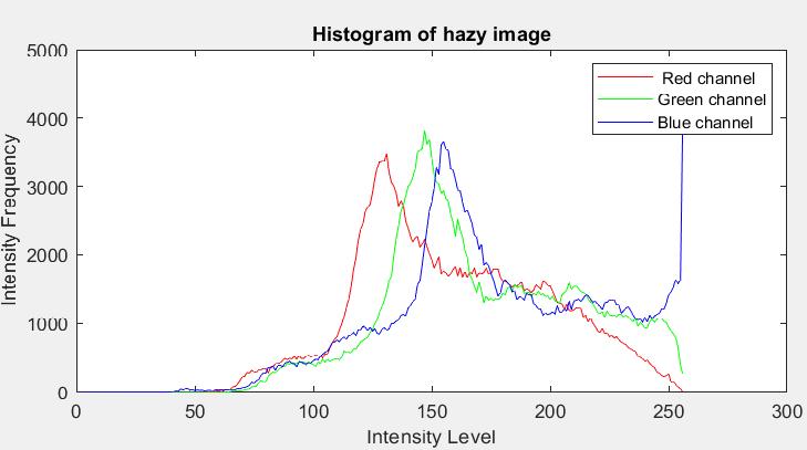
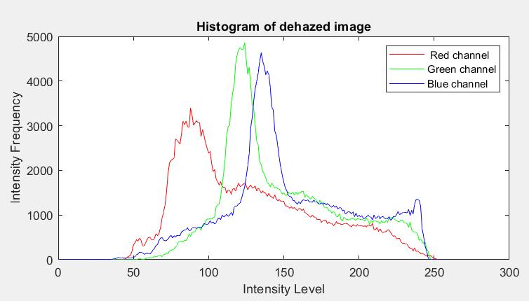
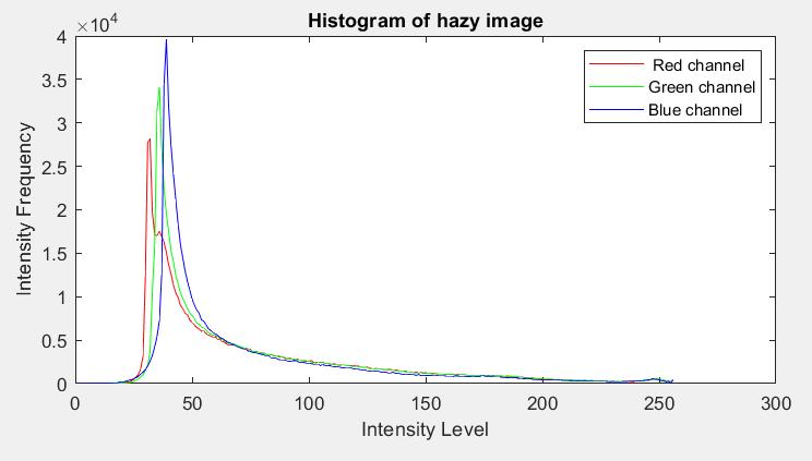
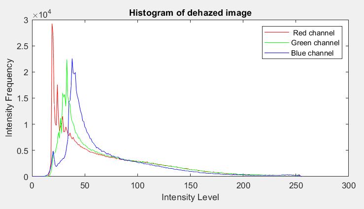
The fig. 4.1, 5.1 and 6.1 shows the Color Histograms of respective input and output images. The color histograms presents the color characteristics of the image. The color histogram distribution becomes more even and are enhancedincolorintensityafterthehazeremoval.Hence, the hazy and haze free color histograms should be structurallysimilar.
Fig : Illustrationofcontrastenhancementmethodona m x n lowlightintensityimage:(a)Thelowlightintensity inputimage, I. (b)Theinvertedimageofinput, Inv.(c)The dehazedimage, D.(d)Thefinaloutputimage, O
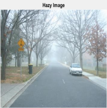
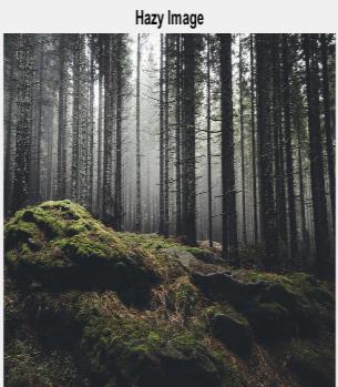
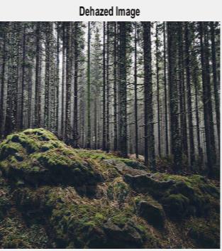
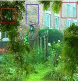
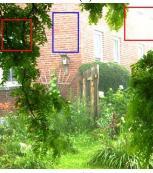
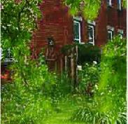
The following fig. 4 6 demonstrates the outcomes of the proposed novel dehazing method. The input hazy images and the output haze free images are at the left and right sideoftheresultrespectively. From the fig. 4 6, which gives the results of the proposed novel dehazing algorithm, it is clear that the proposed noveldehazingmethodeffectivelyeliminatesthehazeand improvesthevisibilityofthehazefreeimage.
5. EXPERIMENTAL RESULTS
Fig 4 :ImageDehazingresultofparkimage
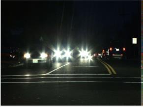
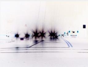
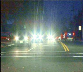
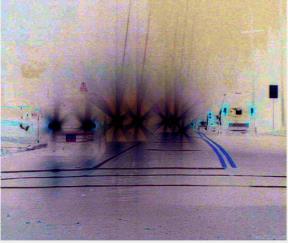
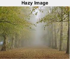
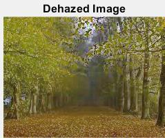
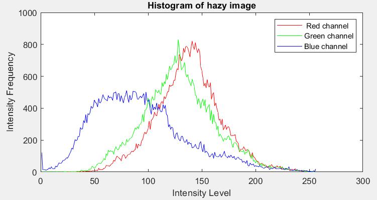
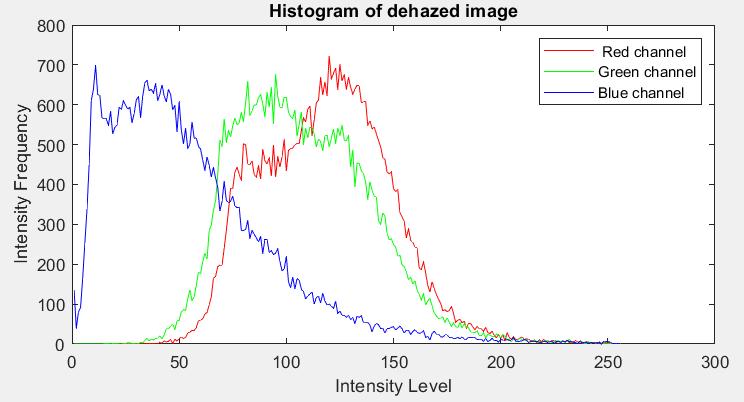


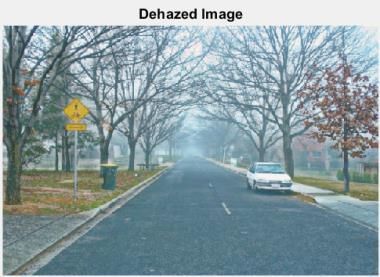
Fig 5 :Imagedehazingresultsofroadimage.
International Research Journal of Engineering and Technology (IRJET) e ISSN: 2395 0056 Volume: 09 Issue: 01 | Jan 2022 www.irjet.net p-ISSN: 2395-0072 © 2022, IRJET | Impact Factor value: 7.529 | ISO 9001:2008 Certified Journal | Page15
Fig 5.1:Histogramsof roadimage.(a)Hazyinputimage. (b)Outputdehazedimage.
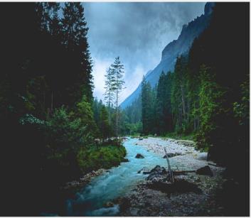
Fig-6 : ImageDehazingresultofForestimage.
Fig 6.1 :Histogramsofforestimage.(a)Hazyinputimage. (b)Outputdehazedimage.
Table 1 presents the comparison between the visibility metric of input Hazy and output Haze free images for fig. 4 6.AsshowninTable 1,thevisibilitymetricoftheinput imageinfig.4is113.2086andafterapplyingtheproposed dehazing method, the visibility metric increased to Input Output (a) (b) Input Output (a) (b)

International Research Journal of Engineering and Technology (IRJET) e ISSN: 2395 0056 Volume: 09 Issue: 01 | Jan 2022 www.irjet.net p-ISSN: 2395-0072 © 2022, IRJET | Impact Factor value: 7.529 | ISO 9001:2008 Certified Journal | Page16 184.377. Similarly, the input image visibility metric of fig. 5and6 was63.5884 and187.1041 respectivelyandtheir respective visibility metric of output images increased to 134.6573and246.7837respectively.Basedonthereading in Table 1, it is clear that the proposed novel dehazing approachincreasesthevisibilityoftheimage. TABLE 1 : COMPARISONOFVISIBILITYMETRICOF HAZYANDHAZE FREEIMAGES Image ImageSize Visibility Metric inIncrementvisibilitymetricImageInputHazy HazeOutputfreeimage Park 194x259 113.2086 184.377 71.1684 Road 400x600 63.5884 134.6573 71.0689 Forest 662x1000 187.1041 246.7837 59.6796 Fig-7 :Comparisonofresultsonhouseimage.(a)Hazy inputimage.(b)Meng’smethodoutput.(c)Gibson’s methodoutput.(d)Proposednoveldehazingmethod. The image above used to compare the results of various methods is of size 223x226 and is shown in fig. 7. The proposednoveldehazingmethodiscomparedwithMeng’s approach and Gibson’s approach. Fig. 7 (b) and (c) suffer from color shifting and also contains some artefacts. The proposed method clearly removes the haze without any colorshift.
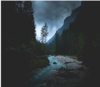
Fig 8 :EnhancementmethodresultonRiverimageofsize 667x1000.
TABLE 2 : COMPARISONOFELAPSEDTIME Method Elapsed Time (s) Gibson’s 0.6616 Wang’s 5.4169
Jeong’s 2.9743 Fattal’s 0.9685 Proposed 0.6428
Table 2 presents the comparison of Elapsed time. The duration from when the process started until the time it terminatedisElapsedtime.Bystudyingtheabovetableof the elapsed time, it is clear that the elapsed time of the proposed novel dehazing method is competitive with thoseofothermethods. 5.2. Results of contrast enhancement method for low light intensity images
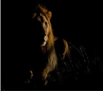
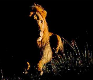
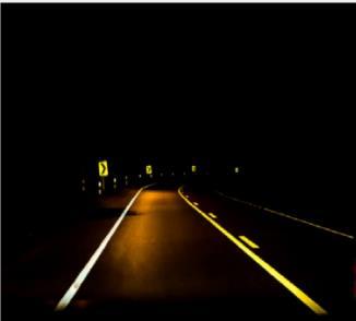
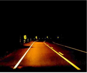
From the fig. 8 10, which shows the results of the proposed enhancement method on low light intensity images,itisclear thattheproposed method enhancesthe low dynamic range images, it increases the quality of the imageandmakesitstandoutmoreclearly
Fig- 9 :EnhancementmethodresultonRoadimageofsize 667x1000. (a) (b) (c) (d) InputOutput InputOutput
The following fig. 8 10 shows the results of the proposed enhancementmethod.Theimagesontheleftareinputlow light intensity images and the images on the right are enhancedoutputimages.

[4] Oakley, “Correction of simple contrast loss in color images”, IEEE Trans. on image processing, no.2, 2007. [5] K.He,J.Sun,andX.Tang,‘‘Singleimagehazeremoval using dark channel prior,’’ IEEE Trans. Pattern Anal. Mach. Intel., vol. 33, no. 12, pp. 2341 2353, Dec. 2011. [6] Yang and Z. Li, “Super pixel based single image haze removal”, Proc. Chin. Control Decis. Conference, Yinchuan,China,pp.1965 1969,2016. [7] Jeong and Lee, “The single image dehazing based on efficient transmission estimation”, vol. 35, no. 6, Jun. 2013. [8] Wang,LeeandLian,“Multiplescatteringmodelbased image dehazing with super pixel”, Acta Photonica Sinica,vol.45(4),2016. [9] Meng, Wang, Duan Xiang an C. Pan, “Efficient image dehazing with boundary constraint and contextual regularization”, Proc. IEEE International Conference Comput. Vis., Sidney, NSW, Australia, pp. 617 624, 2013. [10] Wang, “A Novel Dehazing Method for color Fidelity and Contrast Enhancement on mobile devices”,IEEE Transaction on consumer electronics, Vol. 65, No. 1, Feb2019. [11] K. He, J. Sun, and X. Tang, “Guided Image Filtering”, IEEE Trans. on pattern analysis and machine Intelligence,vol.35,no.6,Jun.2013,pp.1397 1409.
This work is supported by Department of Electronics and Communication Engineering, Bangalore Institute of Technology.
Anoveldehazingapproachispresentedinthispaperin favour of the color accuracy of the images taken on the smart phones or digital cameras. And a contrast enhancement method is proposed for the low light intensity images. The proposed dehazing method first performs region division based on white balance segmentation and bit level processing. Then local atmospheric light is estimated in each region. Finally, iterative dehazing is performed until the image is haze free. The proposed enhancement method first inverts the low light image, then performs the dehazing on the invertedimageandagaininvertstheresultofthedehazing imagetoobtaintheenhancedimage.Experimentalresults indicates that the presented novel dehazing method and enhancementmethodcanbeappliedtotheextendedareas ofimageprocessingandarecomputationallyefficient.
REFFERENCES
[2] B. Gibson and T. Q. Nguyen, “An investigation of dehazing effects on images and video”, IEEE Trans. ImageProcess,vol21,no.2,pp.662 673,Feb.2012 [3] Tarel, “Fast visibility restoration from a single color or Gray level image”, Proc. IEEE International conference on computer vission, pp. 2201 2208, 2009.
ACKNOWLEDGMENT
[12] Zheng and Zhu, “Content adaptive Guided Image Filtering”, IEEE International Conference on Multimedia and Expo., Chengdu, China, pp. 11, Jul. 2014. [13] Nayar and Narasimhan, “Vision in Bad Weather”, IEEE International Conference on Comput. Vission, pp.820 827,1999. [14] Dong, “Fast Efficient Algorithm for Enhancement of LowLightVideo”,MultimediaandExpo(ICME),2011, IEEEInternationalConference. Input Output
[1] Fattal, “Single Image Dehazing”, ACM Trans. Graph, Vol.27,no.72,pp.1 9,Aug.2008.
International Research Journal of Engineering and Technology (IRJET) e ISSN: 2395 0056 Volume: 09 Issue: 01 | Jan 2022 www.irjet.net p-ISSN: 2395-0072 © 2022, IRJET | Impact Factor value: 7.529 | ISO 9001:2008 Certified Journal | Page17 Fig 10 :EnhancementmethodresultonLionimageofsize 530x800. 6. CONCLUSION