International Research Journal of Engineering and Technology (IRJET)
e-ISSN: 2395-0056
Volume: 08 Issue: 09 | Sep 2021
p-ISSN: 2395-0072
www.irjet.net
COMPARISON BETWEEN BOOST CONVERTER AND ZETA CONVERTER FOR HARMONIC REDUCTION OF FUEL CELL SYSTEM Tasaffi Anjum M.Tech Scholar, Dept. of EE, SSCET, Bhilai, India ----------------------------------------------------------------------***--------------------------------------------------------------------2H2 + O2 + Heat Abstract -: This paper deals with the modeling, analysis and control scheme of fuel cell system using DC converter. The output of the Fuel Cell system is connected to the DC side of the Voltage Source Inverter (VSI) for interfacing to the utility Grid. The behavior of a fuel cell by varying DC link voltage which makes change in the output of the active power has been investigated. The DC to DC converter is a Quadratic Boost Converter (QBC), implemented with fixed frequency Pulse Width Modulation (PWM) based sliding-Mode Control technique which enables a tight voltage regulation besides offering a good dynamic performance. Finally, the work will present the main obtained conclusions, indicating the main aspects of FUEL CELL, which must be considered in the application of this device USING DC Converter.
Key Words: Fuel cell, DC DC Converter, Boost converter, ZETA Converter
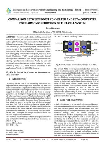
1. INTRODUCTION According to the rate of the increasing population our requirement of everything is also increased. To meet the basic necessities the large number of sources is required to fulfil our all needs. According to our present requirement we suggest to utilize the fuel cell in the form of energy generation [1]. It will give better generation of energy among all others various resources. This form of energy is highly efficient, economical, and flexible and pollution free. Fuel cell is device which is used for the conversion of chemical energy into electrical energy with the help of electrochemical reaction. Fuel Cell is an electro chemical device which converts fuel and oxidant into DC electricity [2]. Cells that take up oxygen, for the cathode reaction, from ambient air by passive means are known as “air-breathing” fuel cells (ABFC. In the ABFC, hydrogen and oxygen are fed at anode and cathode respectively as reactants. The electrons will move to the cathode through external load and protons travel through the electrolyte membrane as shown in Fig. 1. Anode side reaction: H2 Cathode side reaction: O2 + 4H+ + 4eOverall reaction: © 2021, IRJET
|
Impact Factor value: 7.529
|
Fig. 1: Work process and reaction principle of an ABFC The overall ABFC power system includes fuel cell stack, power conditioning units, and control units. The power conditioning circuits (PCU) includes DC to DC converter , a boost converter ,ZETA Converter and the Multi level inverter. The boost converter produces output voltage more than the input voltage and controls the unregulated voltage output of the fuel cell stack(60V) and maintains the desired value (230V) using sliding -mode control The boost converter in closed loop mode can achieve good dynamic performance, in addition to load as well as line regulation[3],[4]. The other part of the PC includes Multi level inverter for converting DC to AC. The Multilevel power conversion is a sophisticated technology with excellent potential for further growth.
2. BASIC FUEL CELL SYSTEM A fuel cell is defined as an electrical cell, which unlike other storage devices can be continuously fed with a fuel in order that the electrical power can be maintained. fuel cells convert hydrogen or hydrogen-containing fuels, directly into electrical energy, heat, and water through the electrochemical reaction of hydrogen and oxygen[5]. As illustrated in this figure, the fuel such as natural gas, coal, methanol, etc. is fed to the fuel electrode (anode) and oxidant (oxygen) is supplied to the air electrode (cathode). The oxygen fed to the cathode allows electrons from the external electrical circuit to produce oxygen ions. The ionized oxygen goes to the anode through the solid electrolyte and combines with hydrogen to form water. Even though chemical reactions at anode and cathode may be a little different according to the types of fuel cells, the overall reaction can be described as follows: ISO 9001:2008 Certified Journal
|
Page 149