International Research Journal of Engineering and Technology (IRJET)
e-ISSN: 2395-0056
Volume: 08 Issue: 06 | June 2021
p-ISSN: 2395-0072
www.irjet.net
An Approach towards Prototyping Wireless Test Receiver Module and its Firmware Development for Testing Wireless Chargers Megharanjini R1, Dr. Roopa M2 1PG Student – M.Tech, VLSI Design and Embedded Systems, Dept. of ECE, DSCE Bangalore, Karnataka 2Professor, Dept of ECE, DSCE Bangalore, Karnataka
---------------------------------------------------------------------***---------------------------------------------------------------------
Abstract - The charging of mobile phones has become more
wireless charging strategies and advancement of profitable commodities have given a promising different approach to address the energy shortcomings of traditionally convenient battery-controlled electronic devices – mobile phone being a main concern in this paper.
appealing since the time the Wireless Power Transfer (WPT) innovation has been developed. The transmitter being the wireless charging pad and the receiver being the mobile phone, both must be Qi compliant. A mobile phone cannot be utilized to check all the functionalities of the transmitter. For this reason, a Wireless Test Receiver Module can be made for clients to verify a wireless charging pad. In this paper, a model for Wireless Test Receiver Module is made and firmware is created for Wireless Test Receiver Module. The Wireless Test Receiver IC is Qi 1.2.3 with up to 15W charging limit. The main components are Wireless Charger Receiver, Microcontroller Unit (MCU) and Organic Light Emission Display (OLED). The objective is to build firmware which runs inside MCU to know the various constraints like Power, Output current, Temperature of IC, Operating frequency. The read constraints must be displayed on the OLED display. In the event of any faults, the constraints must be identified and an error message must be shown in the OLED.
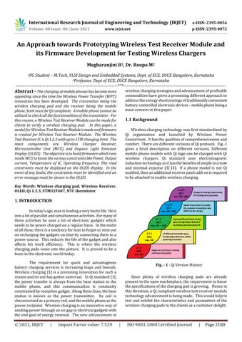
1.1 Background Wireless charging technology was first standardized by Qi organization and launched by Wireless Power Consortium. It has the qualities of comprehensiveness and comfort. There are different versions of Qi protocol. Fig.-1 gives a brief description on different versions. Different mobile phone models with Qi logo can be charged with Qi wireless chargers. Qi standard uses electromagnetic induction technology as it has the benefits of simple to create and minimal expense [3] [4]. If a phone model is not Qi enabled, then an additional receiver patch add-on is required to be attached to enable wireless charging.
Key Words: Wireless charging pad, Wireless Receiver, OLED, Qi 1.2.3, STM32F407, NTC thermistor
V 1.2.4 2017 max. 5W -30W
1. INTRODUCTION
V 1.2.3 2017 max. 5W - 30W
In today’s age, man is leading a very hectic life. He is into a lot of parallel and simultaneous activities. For many of these activities he uses a lot of electronic gadgets which needs to be power charged on a regular basis. In the midst of all these, there is a tendency for man to forget or miss out on recharging the gadgets on time by connecting them to a power source. This reduces the life of the gadget and also affects his work efficiency. This is where the wireless charging pads come into the picture. It is proved to be a boon in the electronic world today.
V 1.2 2015 max. 5W – 15W
V 1.1 2012 max. 5W V 1.0 2010 max. 5W
The requirement for quick and advantageous battery charging services is increasing leaps and bounds. Wireless charging [1] is a promising innovation for such a reason and its use has gotten universal. In Qi standard [1], the power transfer is always from the base station to the mobile phone, and this communication is constantly constrained by reception gadget. Along these lines, the base station is known as the power transmitter. Its coil is characterized as a primary coil, and the mobile phone as the power recipient. Wireless charging is an innovative way of sending power through an air gap to electrical gadgets with the end goal of energy renewal. The new advancement in
© 2021, IRJET
|
Impact Factor value: 7.529
Changes to testing requirements, EPP testing more accessible
Added Power class 0 to enable the customer to negotiate upto 30W from the charger
Improved Thermal tests, timing specs, foreign object detection sensitivity, optional receiver ID
12 different transmitte specs., foreign object detection, added powering transmitter
Single coil, coil array or moving coil Power transmitter
Fig. - 1 : Qi Version History Since plenty of wireless charging pads are already present in the open marketplace, the requirement to know the specifications of the charging pad is growing. Hence in this direction, a Qi compliant wireless test receiver module technology advancement is being made. This would help to test and exhibit the characteristics and parameters of the wireless charging pads to the clients as a customer delight.
|
ISO 9001:2008 Certified Journal
|
Page 2180
International Research Journal of Engineering and Technology (IRJET)
e-ISSN: 2395-0056
Volume: 08 Issue: 06 | June 2021
p-ISSN: 2395-0072
www.irjet.net
2. PROPOSED DESIGN
In display technology using Inter Integrated Circuit I2C there are 2 prominent methods namely OLED and LCD [2]. In the proposed methodology in this paper, OLED is chosen over LCD. The main reason for this choice is for the fact that each pixel in OLED can be controlled. Backlighting is not required in OLEDs but in LCSs most of the power is consumed for backlighting. This is the reason why OLEDs consume very less power when compared to LCDs. This feature plays an important role in the battery operated devices like mobile phones and others. OLEDs have one more characteristic – they produce their own light. This makes it more advantageous like they provide a very wide viewing range.
Main objective is to design a Wireless Test Receiver Module and develop firmware to make the wireless test receiver module to test the Wireless Charging Pads and its functionalities by displaying the proper messages on the OLED display. The proposed design of Wireless Test Receiver Module is shown in Fig.–2.
3. METHODOLOGY Data is read from receiver IC through I2C configuration and displayed on OLED display through I2C configuration. Here the MCU is the master, receiver IC and OLED display are the slaves. Read different parameter data from registers of P9221-R3 through I2C interface. The parameters to be read are: Output Voltage: Output voltage is read by the following formula VOUT = Output current: Output current is read by the following formula IOUT =
Fig. - 2 : Proposed design of Wireless Test Receiver Module To build a Wireless Test Receiver Module one can go for a custom Printed Circuit Board (PCB) or for experimental purpose one can choose Renesas WP15WBD-RK Evaluation Kit.
Output power: Output power is read by the following formula POUT =
Hardware components considered for experimental purpose are - a custom PCB, STM32F407 discovery board, OLED Display, Rheostat, wireless charging pad.
Temperature of IC: Temperature of IC is read by the following formula TDIE = (ADC_Die_Temp − 1350) – 273
Components on a custom PCB are: P9221- R3 receiver IC, fixed load of 9.6 ohms and Negative Temperature Coefficient (NTC) thermistors that are populated on the PCB to monitor temperature of the load and receiver coil. The transmitter is a third party wireless charging pad. Both the transmitter and receiver are Qi 1.2.3 compliant.
Operating resonant frequency: Operating resonant frequency is calculated by the following formula Fop = In the above mentioned formulas, ADC_VOUT, RX_IOUT, ADC_Die_Temp are the values read from the receiver IC registers through I2C.
To read the values from the receiver IC registers, STM32 IC is used as MCU. Here STM32F407 Discovery Board is used. This MCU is programmed using STM32Cube IDE software tool.
The read parameters are displayed on OLED. With each click on Tactile Switch - read through a GPIO input, different parameters should be showing one by one.
To vary the power from 0W to 15W, Rheostat is used as an external load. Wires are drawn from custom PCB test points for rheostat connection.
© 2021, IRJET
|
Impact Factor value: 7.529
For status indication, Light Emitting Diodes (LEDs) are used. Green LED is used to indicate normal operating
|
ISO 9001:2008 Certified Journal
|
Page 2181
International Research Journal of Engineering and Technology (IRJET)
e-ISSN: 2395-0056
Volume: 08 Issue: 06 | June 2021
p-ISSN: 2395-0072
www.irjet.net
conditions and Red LED is used to indicate any abnormal conditions. The STM32F407 Discovery board has four on board user LEDs. Green LED is connected to pin PD12 and red LED is connected to pin PD14. These LEDs can be GPIO configured. External LEDs can also be used. Fig.– 3 shows the pinout view of STM21F407 IC in STM32CubeIDE.
There are many ways or reading the temperature. Look up table method, Steinhart – Hart equation and B parameter equation are some of the methods for calculating the temperature. In this paper B parameter equation is used for temperature calculation. The dependence of the resistance on temperature can be approximated by the following equation:
where R -NTC resistance in Ω at temperature T in K RR - NTC resistance in Ω at rated temperature TR in K T - Temperature in K TR - Rated temperature in K B - B value in K, material-specific constant of NTC thermistor e - Euler number (e = 2.71828)
4. RESULTS The various parameters read from the third party wireless charger is as follows Parameters
Value
Output Voltage
12 V
Fig. - 3 : Pinout view of STM32F407 IC in STM32CubeIDE
Output Current
1.25 A
NTC thermistors are used for temperature monitoring [5]. NTC shows a change in resistance with change in temperature. Resistance and temperature are inversely proportional for a NTC. Wires are drawn from custom PCB test points and are given as input to the MCU. In order to measure temperature properly, a potential divider network is used. Temperature calculations is done by programming ADC (Analog to Digital Converter). The output value from potential divider network is given as input ADC. Fig.–4 shows the NTC circuit diagram. Along with potential divider circuit, a RC (Resistor – Capacitor) low pass filter is used to remove the undesired signals.
Operating Frequency
127.5 KHz
Output Power
15 W
Die Temperature
62°C
5. CONCLUSIONS P9221 - R3 is a standalone IC. No external IC is required to control the IC. The purpose of STM32 used is to monitor the IC and display the different parameters on the OLED display. By using this Wireless Test Receiver Module, one may check the different parameters of the wireless charging pad before buying or embedding it into any surface. In this paper, an experimental setup has been made with the proposed design. Further, a single custom PCB with all the above discussed components can be used to build a complete Wireless Test Receiver Module.
REFERENCES [1]
Fig. - 4 : NTC circuit
© 2021, IRJET
|
Impact Factor value: 7.529
|
X. Lu, P. Wang, D. Niyato, D. I. Kim and Z. Han, "Wireless Charging Technologies: Fundamentals, Standards, and Network Applications," in IEEE Communications Surveys & Tutorials, vol. 18, no. 2, pp. 1413-1452, Secondquarter 2016, doi:
ISO 9001:2008 Certified Journal
|
Page 2182
[2]
[3]
[4]
[5]
International Research Journal of Engineering and Technology (IRJET)
e-ISSN: 2395-0056
Volume: 08 Issue: 06 | June 2021
p-ISSN: 2395-0072
www.irjet.net
10.1109/COMST.2015.2499783. M. Young, The Technical Writer’s Handbook. Mill Valley, CA: University Science, 1989. Phadke, A. (2019). An Overview of Current Display Technologies and Possible Future Technologies. 2019 IEEE International Conference on Electrical, Computer and Communication Technologies (ICECCT). doi:10.1109/icecct.2019.8869539 WPC, "QI - MOBILE COMPUTING", [Online]. Available: WPC,https://www.wirelesspowerconsortium.com/qi. [Accessed July 16, 2019]. WPC, "Qi specifications", Part 1&2, p.10 [Online]. Available:WPC,https://www.wirelesspowerconsortium. com/knowledgebase/specifications/download-the-qispecifications.html. [Accessed July 16, 2019]. Y. LIU, Y. LIU, W. ZHANG and J. ZHANG, "The Study of Temperature Calibration Method for NTC Thermistor," 2020 IEEE 4th International Conference on Frontiers of Sensors Technologies (ICFST), 2020, pp. 50-53, doi: 10.1109/ICFST51577.2020.9294760.
© 2021, IRJET
|
Impact Factor value: 7.529
|
ISO 9001:2008 Certified Journal
|
Page 2183