International Research Journal of Engineering and Technology (IRJET)
e-ISSN: 2395-0056
Volume: 08 Issue: 05 | May 2021
p-ISSN: 2395-0072
www.irjet.net
such as mobile phone, PDAs, Headphone, etc. To communicate and exchange data between mobile devices by Ericson it has been developed. The Bluetooth technology used in the802.15 standard operates in the 2.4 GHz frequency band. Voice and Data transmission between Bluetooth powered which range between above 10 and 100 meter them [7]. The hc-05 Bluetooth sensor is a sensor that allows wireless communication between devices using Bluetooth technology. The HC-05 Bluetooth sensor support Bluetooth 2.0 operates in the 2.4 GHz frequency band and operates at a communication distance of about 10 meters. Scopes are used in both hobby and project studies. There is 26 MHz crystal oscillator. REF Antenna, 8 MB flash memory, 6 interactive pins (Status, IX, GNDF, VCC, and EN) figure shows example connection between the HC-05 sensor and Arduino Mega [9].
In this modeling CATIA v5 software to use making a design. CATIA means computer added threedimensional interactive application. This software is multi plate form software suite computer aided design (CAD), computer aided manufacturing (CAM), and computer aided engineering (CAE), PLM and 3D developed by dassaults Systems Company. CATIA is started as 1977. CATIA can be applied to a wide variety of industries. CATIA used to reason is this CATIA tool is in the design of the various object as arm, end effecter, chuck, base, and many part etc. much as other CAD systems, this tool perform many function such as basic volume. This is also used as the perform a mesh analysis give to any load. It is also used as the numerical control for a drilling machine, tapping machine, and milling machine. In this CATIA following toolbar are used 1) start, mechanical design, part design 2) sketcher 3) sketch based features 4) view 5) product structure tool 6) view and different tools are use the complete design is show In Fig.
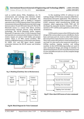
Voice command
Yes
No
Fig. 5: Modeling (Courtesy: How to Mechatronics)
First Arm Activated Input Speech Signal
Preproce ssor
Feature Extensio n
Second Arm Activated Drilling Arm Activated Tapping Arm Activated
Working
Classify comman d Yes/No
Fig.07: Flow chart Of Process of voice command
Fig.06: Block Diagram for Voice Command
© 2021, IRJET
|
Impact Factor value: 7.529
|
ISO 9001:2008 Certified Journal
|
Page 2824


