International Research Journal of Engineering and Technology (IRJET)
e-ISSN: 2395-0056
Volume: 08 Issue: 04 | Apr 2021
p-ISSN: 2395-0072
www.irjet.net
DETECTION OF FAULT IN GAS TURBINE USING MATLAB SIMULINK 1Abhijeet
Verma, 2Aakash deep Dabas, 2Prof. Narendra Kumar
1B.Tech,
Delhi Technological University, Shahbad Daulatpur, New Delhi-110042 Delhi Technological University, Shahbad Daulatpur, New Delhi-110042 3Professor Narendra Kumar, Dept. of Electrical Engineering, Delhi Technological University, New Delhi, India ---------------------------------------------------------------------***--------------------------------------------------------------------1.1 Block Diagram Abstract - Gas turbines are one of the important equipment 2B.Tech,
in the field of power. They are very much used in power generation, factories, industries and many other platforms. However, G.T’s are not being monitored manually in most of the cases. Safety is considered as one of the important factor for smooth working of gas turbines. If any fault occurs in the system then it can be very serious. There is a much need of new technologies and techniques to be developed for fault detection. In this paper, we we will make an automatic or non manual system for the detection of fault in Gas Turbines. Also in this paper, simulation modelling of the G.T is being
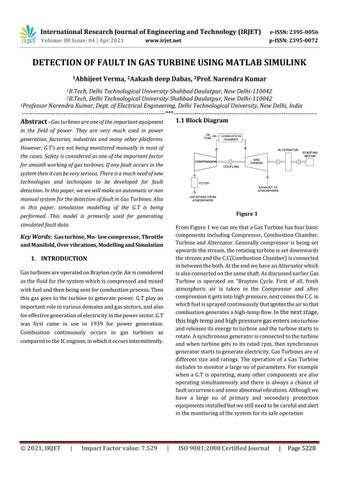
Figure 1
performed. This model is primarily used for generating simulated fault data.
From Figure 1 we can see that a Gas Turbine has four basic components including Compressor, Combustion Chamber, Turbine and Alternator. Generally compressor is being set upwards the stream, the rotating turbine is set downwards the stream and the C.C(Combustion Chamber) is connected in between the both. At the end we have an Alternator which is also connected on the same shaft. As discussed earlier Gas Turbine is operated on "Brayton Cycle. First of all, fresh atmospheric air is taken in the Compressor and after compression it gets into high pressure, next comes the C.C in which fuel is sprayed continuously that ignites the air so that combustion generates a high-temp flow. In the next stage, this high temp and high pressure gas enters into turbine and releases its energy to turbine and the turbine starts to rotate. A synchronous generator is connected to the turbine and when turbine gets to its rated rpm, then synchronous generator starts to generate electricity. Gas Turbines are of different size and ratings. The operation of a Gas Turbine includes to monitor a large no of parameters. For example when a G.T is operating, many other components are also operating simultaneously and there is always a chance of fault occurrence and some abnormal vibrations. Although we have a large no of primary and secondary protection equipments installed but we still need to be careful and alert in the monitoring of the system for its safe operation
Key Words: Gas turbine, Mu- law compressor, Throttle and Manifold, Over vibrations, Modelling and Simulation
1. INTRODUCTION Gas turbines are operated on Brayton cycle. Air is considered as the fluid for the system which is compressed and mixed with fuel and then being sent for combustion process. Then this gas goes to the turbine to generate power. G.T play an important role in various domains and gas sectors, and also for effective generation of electricity in the power sector. G.T was first came in use in 1939 for power generation. Combustion continuously occurs in gas turbines as compared to the IC engines, in which it occurs intermittently.
© 2021, IRJET
|
Impact Factor value: 7.529
|
ISO 9001:2008 Certified Journal
|
Page 5228