International Research Journal of Engineering and Technology (IRJET)
e-ISSN: 2395-0056
Volume: 08 Issue: 03 | Mar 2021
p-ISSN: 2395-0072
www.irjet.net
Harmonic Analysis of Three Phase 3-Level and 5-Level CHB Multilevel Inverter using SPWM Technique Karishma Patel1, Gaurang Patel2 1M.E
Student, Electrical Department, Mahatma Gandhi Institute of Technical education and Research center Navsari-396450, Gujarat, India 2Assistant Professor, Electrical Department, Mahatma Gandhi Institute of Technical education and Research center,Navsari-396450, Gujarat, India ----------------------------------------------------------------------***--------------------------------------------------------------------Abstract - Multilevel Inverter technology has emerged recently as a very important alternative in the area of high power, high voltage energy control. It came into picture and it has gained more attention in market for various applications like renewable energy systems, industrial motor drives, etc. It can generate stepped waveform by reducing harmonic distortion with increase in the number of voltage level. The main advantages of this multilevel inverter are that it generates very less harmonics. In this paper, one carrier based PWM technique is proposed i.e. level shifted scheme which can minimize the total harmonic distortion and enhances the output voltage. Level Shifted [LS] Scheme is applied to the Cascade H-bridge multilevel inverter and the complete analysis of THD three level to five levels is done.
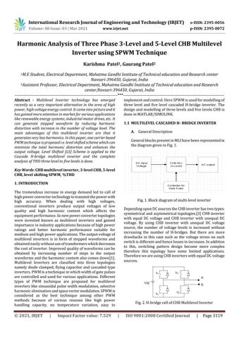
implement and control. Here SPWM is used for modelling of three level and five level cascaded H-bridge inverter. The design and modelling of three levels and five levels CHB is done in MATLAB/SIMULINK. 1.1 MULTILEVEL CASCADED H- BRIDGE INVERTER A. General Description General blocks present in MLI have been represented in the diagram given in Fig. 1.
Key Words: CHB multilevel inverter, 3-level CHB, 5-level CHB, level shifting SPWM, %THD 1. INTRODUCTION The tremendous increase in energy demand led to call of high power converter technology to transmit the power with high accuracy. When dealing with high voltages, conventional inverters produce output voltages of low quality and high harmonic content which affects the equipment performance. So new power converter topologies were invented known as multilevel inverters and gained importance in industry applications because of high power ratings and better harmonic performance suitable for medium and high power applications. The output voltage of multilevel inverters is in form of stepped waveforms and obtained easily without use of transformers which decreases the cost of inverter. Improved quality of waveforms can be obtained by increasing number of steps in the output waveforms and the harmonic content also comes down[1]. Multilevel Inverters are classified into three topologies namely diode clamped, flying capacitor and cascaded type inverters. PWM is a technique in which width of gate pulses are controlled and used for various applications. Different types of PWM technique are proposed for multilevel inverters like sinusoidal pulse width modulation, selective harmonic elimination and space vector modulation. SPWM is considered as the best technique among other PWM methods because of various reasons like high power handling capacity, no temperature variation, easy to
© 2021, IRJET
|
Impact Factor value: 7.529
Fig. 1. Block diagram of multi-level inverter Depending upon DC sources the CHB inverter has two types: symmetrical and asymmetrical topologies.[3] CHB inverter with equal DC voltage and CHB inverter with unequal DC voltage. By using CHB inverter with unequal DC voltage source, the number of voltage levels is increased without increasing the number of H-bridges. But there are more drawbacks in this case such as the voltage stress on each switch is different and hence losses in increases. In addition to this, switching pattern design become more complex therefore this topology have some limited applications. Therefore we are using CHB inverters with equal DC voltage sources.
Fig. 2. H-bridge cell of CHB Multilevel Inverter
|
ISO 9001:2008 Certified Journal
|
Page 3119