ii. Withtheuseofanitrogenblanketonstoragetanks andstorageoffuelinawell sealeddrumOxidation offuelwhichistheremovalofoxygenfromthefuel canbeachievedandstoragelifecanbeprolonged.
Key Words: Environment, Product, Safety, Storage, Temperature.1.INTRODUCTION
Temperature control is the measurement of temperature transition of an object collectively within a space and the passageofheatenergyisalternatedinandoutofthespace in other for the average temperature to be achieved. In ensuringthestabilityandsafetyofaprocessproductthere are various methods that can be applied in measurement andcontroloftemperatureofthestoragesystems.Stability can be referred to two main issues for fuels: stability at elevated temperature and pressure of the recirculation of fuel in an engine system and aging or long term storage stability [1]. In petroleum products, Stability of fuel temperature at elevated fuel system is referred to as ThermalstabilitywhileOxidativestabilityasthelong term storagestability. The principles which help in identifying combustible, flammable and storage conditions in order to ensure the highestlevelofstabilityare[2]: i. Fluidsmustbestoredinaseparatestoragesystem awayfromthestorageofmetalslikelead,rust,zinc, brassbronze,tin,copperandironsoastoreducea high means of sedimentation and its degradation processes.
iv. Sunlight and heat can significantly facilitate these processes.
v. Antioxidants either incorporated as additives or naturalcangreatlyincreasethestabilityoffluidsas wellasitsstoragelife.
2MCVOU Limited, #6 White House Peace Land Estate, Lagos, Nigeria.
International Research Journal of Engineering and Technology (IRJET) e ISSN: 2395 0056 Volume: 08 Issue: 12 | Dec 2021 www.irjet.net p ISSN: 2395 0072 © 2021, IRJET | Impact Factor value: 7.529 | ISO 9001:2008 Certified Journal | Page546 Temperature Control Mechanism, A Panacea for Effective Fluids Storage Nsan Awaji Peterson Ene Nte1 , Matthew Olubiwe1 , Isdore Onyema Akwukwaebgu1 , Oyet Gogomary Israel2 , Samuel Okechukwu Okozi1 , Chisom Patrick Mbachu1 , Samuel Effiom Whiley1
iii. The increase in the unsaturation level from monounsaturated to polyunsaturated causes the stabilityofthefueltoexponentiallydecreasesince the fluids oxidize most likely at a higher level of unsaturationassaturatedfattyacidestersarefairly stable. The reaction of oxygen at the point of unsaturation of the fuel molecules can form peroxideswhichbreaksdownintogums,acidsand sediments.
1Department of Electrical and Electronic Engineering, Federal University of Technology, Owerri, Nigeria.
***
Temperature sensors are highly essential as there are products that greatly rely on temperature control and maintenancetofunctionappropriatelysuchasthermostats, refrigeratorsandoven.Thecontroloftemperatureplaysan importantroleincontrolandprocessengineering,examples whichincludethemaintenanceofachemicalreactoratan idealset pointtemperature,monitoringthetemperatureto guarantee the safety of the personnel in the event of a runaway reaction and to reduce harmful environmental impact,temperatureofthestreamstobereleasedintothe environment should be maintained and monitoring of temperatureoffluidsintankfarms[3].Whiletemperatureis generally sensed by humans as “hot”, “neutral”, or “cold”, control engineering requires precise, quantitative measurementsoftemperatureinordertoaccuratelycontrol aprocess,thisisaccomplishedwiththeaidofatemperature sensorsandthesignalsreceivefromthesensorsarebeing processbythetemperatureregulators.Asheatisaddedtoa system, molecular motion increases which result in the system experiencing an increase in temperature. Temperaturechangesasafunctionoftheaverageenergyof
Abstract There is of course a continuing large scale demand for many of the traditional staple products, but with the intense competition in these areas, the producers will have to make their processes more efficient with adequate storage systems. Sources of raw materials will be more varied and market demand more uncertain, creating the need for more flexible tank storage that is capable of storing economically all the process end products. Tighter environmental constraints and tighter requirements for hygiene, health and safety on the plant means that processes must be more closely monitored. The Resistant Temperature Detector (RTD) is used in areas where high precision is needed and narrow temperature spans are required in order to accurately control a process as to ensure the stability and safety of a process product, the precise and quantitative measurement of temperature is required and this is accomplished with the aid of a temperature sensor and the signals receive from the sensor is being process by the temperature regulators.

amolecularmovementfromathermodynamicsperspective, themeasurementoftheenergyofamolecularmovementis not an easy function as temperature sensors are mainly designedtomeasurethechangeofapropertyinresponseto temperature[4].Thecalibrationofthedeviceisdoneusinga standardinaccordancetothetraditionaltemperaturescale (i.e.,theboilingpointofwateratknownpressure).
International Research Journal of Engineering and Technology (IRJET) e ISSN: 2395 0056 Volume: 08 Issue: 12 | Dec 2021 www.irjet.net p ISSN: 2395 0072 © 2021, IRJET | Impact Factor value: 7.529 | ISO 9001:2008 Certified Journal | Page547
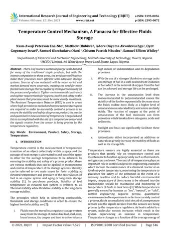
Plate 1: Typical Process Facility and Storage Tanks [5].
2.1 Storage of Flammable Materials. Generally,flammablematerialsmustbekeptseparatelyfrom apotentialignitionsourceinawell ventilatedstorageroom andthesematerialsshouldnotbestoredanywherecloseto electricalequipment’sandshouldbekeptawayfromexits [8]. A flammable material must be placed back into an appropriatecontainershoulditberemovedfromitsoriginal container.
A typical maximum capacity of different volume of tank comprises of 25 85 tanks in the area of 5 55 million barrelsinatankfarm.Aboutthreeweeksofoilproductionis usuallystoredinthestoragetanker,oneweekisscheduled forapropercyclewhiletheotherextraweeksforexpected delays which can amount to millions of barrels.
Althoughthestorageoflocalgasesisdifficult,mostattimes theuseofcavernsorsaltdepositandunderground mines canbeusedinstoringthesegases.Oilandgasaredirectly pipedtoatankerterminaltobestoredinanonboardstorage tank on most production sites without a pipeline to be transportedbyashuttletanker.Thesepetroleumproducts arestoredonconcreteplatformsintanks,onfloatingunits andcellsaroundtheshafts,aseparatestoragetankerisused onsomefloaters.Whenoilvolumediffers,ballasthandlingis highly essential to balance its buoyancy in both cases [5]. Thecrudeoilisstoredinafixedrooftankswhilethefloating rooftanksareusedforcondensateinanonshoreplatform, the use of special tank gauging systems like level radars, pressure or float in moderating the level of storage caves, cellsandtanksisutilized.Dependingonthetankgeometry, itslevelmeasurementisconvertedintoappropriatevolume viatankstrappingtablesandcompensatedfortemperature toprovidestandardvolume.Thefloatgaugecalculatesfor densityandassuchmasscanbeascertained[6].
Plate1showsatypicalprocessfacilityandstoragetankof theoilrefiningindustry.
iv. Ignition sources such as open flames, sparks and heat should be located away from bulk storage containers.
2.2 Storage tanks and rooms. Flammable materials used in production sites should be storedinlargecontainers(tanksordrums),theremaybean excludedstorageroomforthesespecificmaterialsasthey aremostlyinlargevolumesaswellasavailableindifferent types and sizes hence the need for a proper storage. The Alberta Fire Codeoutlines thespecific obligationfor most overhead and underground storage tanks and rooms [9]. Facilities,pipelinesandwellsiteslicensedareapprovedby the Alberta Energy and Utilities Board for production, processing, exploration, handling, treatment, recovery, disposal or transmission of hydrocarbons are covered by Guide 55:[10]. Ingeneral:i.Compressed gases must not be stored beside flammablematerialcontainers.
ii. Flammable material storage areas are highly restrictedforsmokers.
2. STORAGE SYSTEM.
iii. Storage designedroomsventilationsystemsmustbeproperlyandmaintainedonaregularbasis.
v. Other chemicals are to be kept away from the flammable materials bulk storage rooms and containers.
Documentationofaccuratevolumeofwhatisreceivedand dispatchedarekept[7].Therecordofstockmovementand logisticsoperationsarekeptinthetankfarmmanagement system,variousproductandqualityblendingmustsurelybe handledforinstallationthatservemultipleproductionsites.
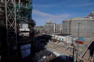
International Research Journal of Engineering and Technology (IRJET) e ISSN: 2395 0056 Volume: 08 Issue: 12 | Dec 2021 www.irjet.net p ISSN: 2395 0072 © 2021, IRJET | Impact Factor value: 7.529 | ISO 9001:2008 Certified Journal | Page548 vi. Bulk storage rooms and areas are to be equipped withspillprotectionhavingappropriatesignageor placarding. vii. The use of large containers in blocking access or being kept near exits of the flammable material storageroomsshouldbecompletelyavoided. 2.3 Incompatible Materials. Incompatibility involves the combination of two or more undesirable and unplanned chemical reactions. The occurrence of incompatibility reactions produces hazard suchas:fireorexplosion,violentreaction,toxicdusts,heat orpressure,mistsandflammablefumesorgases[8]. Chemicalsarenormallygroupedintofivemaincategories; flammable/combustible,acid,alkalineorbasic,oxidizerand reactive.Thesegroupslackcompatibilityassuchshouldbe storedseparatelyfromeachother. Table1clearlyshowssomeincompatiblematerialsthatwill resultsinfireand/orexplosivehazardwhenstoredormixed together. Table 1: Incompatibility of Materials [9]. S/N E + N = P 1 Acidsor (Corrosives)Bases Reactive metals such zincsodiummagnesiumpotassiumlithiumcalciumberylliumaluminumaspowder Fire 2 Cyanide and SulphurGases Acids Fire 3 Solvent or materialsorganicReactive such HydrocarbonsNitratedAldehydesAlcoholsas ReactiveBasesAcidsMetals Explosion 4 Oxidizers such ChromicChloritesChlorineChloratesasacid Hypochlorite’s PerchloratesNitrates WastesCombustibleWastesFlammableSolidsFlaLiquidFlammablemmable Explosion PeroxidesPermanganates 5 LiquidsFlammable PoisonsOxidizersBasesAcids ReactionViolentExplosionFireor 6 GasesCompressedFlammable Oxidizers ReactionViolentExplosionFireor 3. METHODOLOGY Theoretical models of process control are based on conservation laws such as the conservation of mass and energy.Thus, Rateof accumulationmass=Rateofmassin Rateofmassout (1) Also, EA =EINC EOC +HAD +W (2) EWhere; A: Rateofenergyaccumulation. EINC: Rateofenergyinbyconvection. EOC: Rateofenergyoutbyconvection. HAD: Net rate of heat addition to the system from the surroundings. W: Net rate of work performed on the system by the surroundings. Thetotalenergyofathermodynamicsystem,Etot,isthesum ofitsinternalenergy,kineticenergyandpotentialenergy:(3) Assumptions. i. Changesinpotentialenergyandkineticenergycan beneglectedbecausetheyaresmallincomparison withchangesininternalenergy. ii. Thenetrateofworkcanbeneglected,becauseitis small compared to the rates of heat transfer and convection. Fromequation2,theenergybalancecanbewrittenas:

Resistivityofplatinum=10ohm cmat20°C Rt =Rrt (1+ T) (5) =αRrt (6) RWhere; t: Resistanceinohms,attemperatureT. Rrt: Resistance in ohms at a reference temperature (often0°C). : Temperaturecoefficientofresistance. Toprojecttheappropriatevalueoftemperaturegreaterthan 1000°Corlessthan 500°C. Wealsocalculate, (7) Where; : Imperialobtainedfromthemanufacturer. : Temperaturecoefficientofthemetalconductor. Conductordiameter=0.002(standardfromliterature). Resistancevalue=10to500Ohms.
Figure 1 shows the Wheatstone Bridge, which can be adaptedtogiveanindicationanalogoustotemperature.
This is used in areas where high precision is needed and wherenarrowtemperaturespanarerequired.Becausethe electrical resistance of a conductor changes as its temperature varies. The magnitude of the change with respect to 1°C changes in temperature is its temperature coefficientofresistance. Platinum=0.00392ohm/0Coverarangeof0°Cto100°C.It hasalinearcharacteristic.
3.1 Resistance Temperature Detector (RTDs).
A piece of alloy can be connected in series or shunt connectedinternallytoraiseorloweroverallresistanceto standardizeRTDsforinterchangeability.
© 2021, IRJET | Impact Factor value: 7.529 | ISO 9001:2008 Certified Journal | Page549 (4) EWhere; in: Theinternalenergyofthesystem. H: Theenthalpyperunitmass. W: Themassflowrate.Q: Therateofheattransferto the Thesystem.operator denotes the difference between outlet conditionsandinletconditionsoftheliquid. Consequently,the (wH) termrepresentstheenthalpyof theinletliquidminustheenthalpyoftheoutletliquid.
The resistance X represents RTD. The Galvanometer G (a sensitive DC current meter with zero center scale) can be calibrated to deflect accordingly. L which is the lead resistanceasshowninfigure3.2becomesapartoftheX terminalofthebridgecircuit. Since, (8) i.e.,whenthevoltageatnode1equalsthevoltageatnode2, galvanometerGwillexperiencenull(zero)indication. Therefore,theratioofthebridgecomponents. (9) Or (10) G 2 X A 3 4 S E B 1
International Research Journal of Engineering and Technology (IRJET) e ISSN: 2395 0056 Volume: 08 Issue: 12 | Dec 2021 www.irjet.net p ISSN: 2395 0072
Fig. 1: Wheatstone Bridge, the basic circuit for the readout device


Fig 3: Eliminating the effect of Lead Resistance by adding resistance in another terminal of the bridge circuit using a three-wire system to cancel out the lead resistance. 3.3 Null Direct Reading. Resistance A could be replaced by a highly accurate adjustableresistance which iscalibrated tocorrespond to thetemperaturewhichXmeasures. For each new reading, Galvanometer G is set to null electronicallybymeansofresistanceAasshowninfigure4.
Figure 2 shows a two conductor circuit with a lead resistance. Fig. 2: Lead Resistance becomes a part of the measurement in a two-conductor circuit.
International Research Journal of Engineering and Technology (IRJET) e ISSN: 2395 0056 Volume: 08 Issue: 12 | Dec 2021 www.irjet.net p ISSN: 2395 0072 © 2021, IRJET | Impact Factor value: 7.529 | ISO 9001:2008 Certified Journal | Page550
L C G 2 A
Fig. 4: Temperature made analogous to potentiometer setting which nulls the meter in a null direct reading bridge. Also, by placing sliding contacts in both the galvanometer andbatterycircuitloopsasshowninfigure4,theeffectsof contactresistanceareeliminated. ResistancesR1andR2aregaugedsothatpercentageofspan Kis Therefore;equal.withgalvanometeratnull,theequationbecomes. = (13) Or X= (14) The voltage source E can be replaced by an alternately currentsource(normallyf 1000Hz)andresistanceAandB canbereplacedbycapacitorcreatinganACbridge. Thus; = (15) G 2 A 3 4 S E B 1 L L C X G 2 A 3 4 S E B 1 L L 3 4 S E B 1 L L
3.2 Deflection Reading. Byaddingthe resistanceL tobothterminalsofthe bridge circuitasshowninfigure3formeternull,thefollowingratio applies. = (11) Or X=S L (12) Note, the addition of variable resistance C provides the adjustmentofthegalvanometerGtosomeconvenientpoint. ForthevalueofX,Gcanbecalibratedtoreadtemperature Figuredirectly.3 shows the elimination of the effect of lead resistance.


The RTD is made up of an outer sheath material which is composedtoefficientlyconductheattotheresistor, resist degradationfromheatandpreventitfromthesurrounding medium contaminations. The resistance sensor is mostly composedofmetals,suchasnickel,copperorplatinumand responsibleforthetemperaturemeasurement.Thechoiceof material for the sensor strongly determines the range of temperatures wherein the RTD can be utilized. The most common type of resistor, platinum sensor has a range of approximately 200°C 800°C.Thetwoinsulatedconnection leadsareconnectedtotheresistor,theseleadscontinueto completetheresistorcircuit. Figure5showstheschematicdiagramoftheRTDsensor.
Fig. 5: Schematic diagram of Resistance Temperature Detector (RTD). Thereare4mainclassesofRTDsensors,theyarethewire woundthermometers,coilelements,filmthermometersand 187carbonresistors[12]. The187CarbonResistorsareaccurateforlowtemperatures, less expensive, are not affected by strain gauge effects or hysteresis, hence the most used type of RTD sensors by Filmresearchers.thermometersareoftenmadeofplatinumwithavery thinlayerofmetalonaplate,onthemicrometerscalethis layerisverysmall.Basedonthecompositionofthemetal and plate, the thermometers have different strain gauge effect and the type of components used determines its stabilityproblem, Inwire woundthermometersthecoilgivesstabilitytothe measurement.Althoughalargerdiameterofthecoilgives morestability,italsoincreasestheamountinwhichthewire canexpandwhichinturnincreasesstrainanddrift.Hence, they have very good accuracy over a large temperature Therange.coilelementshavegenerallyreplacedthewire wound thermometersinallindustrialapplicationsbecauseoftheir similarityfeatures.Thecoilisallowedtoexpandoverlarge temperature ranges while decreasing the drift and giving support 4. RESULTS
The results obtained on the effect of temperature error differenceusingthePD,PIandPIDcontrollersareshownas follows; Resistance
3.4 Operation of the Resistant Temperature Detector (RTD) Sensor.
Becauseofthepeculiarnatureofpetroleumproducts,most RTDs are made of platinum which is linear over a greater rangeoftemperatures,resistanttocorrosionandbasedits operationuponalinearrelationshipbetweentemperature and resistance, since the resistance increases with temperature. However, in determining a resistor material the following factors such as temperature sensitivity, temperature range, durability and response time must be duly put into consideration [11]. For each of these characteristics, different types of materials have different range.TheprincipleoftheRTDsisbasedupontheCallendar VanDusenequation,whichrelatestheelectricalresistance to the temperature above 0 °C up to the melting point of aluminum which is ~660 °C. Based upon an experimental datafromthespecificRTD,theequationnormallytakesona linearformsinceitismerelyagenericpolynomialandthe coefficientsofthehigher ordervariableisrelativelysmall (a2, a3,etc.).
ConnectionsensorleadsInsulationSheath
International Research Journal of Engineering and Technology (IRJET) e ISSN: 2395 0056 Volume: 08 Issue: 12 | Dec 2021 www.irjet.net p ISSN: 2395 0072 © 2021, IRJET | Impact Factor value: 7.529 | ISO 9001:2008 Certified Journal | Page551 (16) Or (17)


Figure6showsthecontroloftemperatureerrordeviation usingthePDcontroller. 0 500 1000 1500 2000 2500 3000 3500 4000 4500
1.41.20.80.60.40.201
TemperatureerrordifferenceusingPDcontroller
Fig. 6: Temperature Error Deviation using Proportional Derivative (PD) Controller. Figure7showsthecontroloftemperatureerrordeviation usingthePIcontroller.
International Research Journal of Engineering and Technology (IRJET) e ISSN: 2395 0056 Volume: 08 Issue: 12 | Dec 2021 www.irjet.net p ISSN: 2395 0072
0 100 200 300 400 500 600
-0.100.10.20.30.40.50.60.70.80.9
cent)(degreeerrorTemperature
Fig. 7: Temperature Error Deviation from setpoint using Proportional Integral (PI) Controller. Figure8showsthecontroloftemperatureerrordeviation usingthePIDcontroller. 0 500 1000 1500 2000 2500 3000 3500 4000 4500
The simulated result of figure 8 shows the control of temperature using Proportional Integral Derivative (PID) controller.Theerrorisbeingmanipulatedbythecontroller toachievethebestresultastoensurethatthetemperature remainsstable. ItwasdiscoveredthatPIDcontrollergives anexcellentcontrolmeasurewhencomparedwithPIandPD controllers.Table4showstemperatureerrordeviationwith time.
© 2021, IRJET | Impact Factor value: 7.529 | ISO 9001:2008 Certified Journal | Page552
TemperatureerrordifferenceusingPIDcontroller
TemperatureerrordifferenceusingPIcontroller
Time(sec)
Time(sec) cent.)(degreeTemperature
cent.)(degreeerrorTemperature
0.70.60.50.40.30.20.10
Time(sec)
Fig. 8: Action of the PID Controller on the control of the Temperature Error Deviation from set point. The figures, 6, 7 and 8 and tables 2, 3 and 4 shows the simulatedresultsoftemperatureerrordeviationwhenPD, PI,andPIDcontrollerswereusedrespectively. Theoscillogramoffigure6showsthedeviationofsetpoint whenProportionalDerivative(PD)controllerisbeingused. Theessenceistoactuallycomparetheperformanceofthe PD controller with Proportional Integral Derivative (PID) controller.Table2showstemperatureerrordeviationwith Thetime.simulated result of figure 7 shows the control of temperature using proportional integral controller. The error is being manipulated by the controller to achieve a better result so that the temperature could be stable. It is usedtocomparetheperformancewithProportionalIntegral Derivative (PID) controller. Table 3 shows temperature errordeviationwithtime.
[7] S. Jian, H. Kejiang, and X. Xuerui, Risk based InspectionforLargeScaleCrude OilTanks,Journal ofLossPreventionintheProcessIndustryVol.25, pp.166 175,2012.
[4] D. M. Considine, Process Instruments and Control Hand Book, 2nd edition, McGraw Hill Book Company,1974. [5] H. Devold, Oil and Gas Production Handbook. An Introduction to Oil and Gas Production, Transportation, Refining and Petrochemical Industry.ABBOilandGas,ISBN978 82 997886 3 2,Edition3.0Oslo2013.
Table 3: Temperature Error Deviation Control with time using PI TIME (SECONDS) TEMPERATURE (°C) 50 0.89 100 0.09 200 0.91 300 0.93 400 0.96 500 0.99 600 0.1
[8] F. P. Lees, Hazard Identification, Assessment and Control,JournalofLossPreventionintheProcess Industries, Elsevier Butterworth Heinemann Ltd. 2005. [9] Alberta Fire Code, Handling and Storage of Flammable Materials at the Work Site Fire and Explosives 2007 [online]. Available at: www.uregina.ca.[Accessed:17June,2021].
International Research Journal of Engineering and Technology (IRJET) e ISSN: 2395 0056 Volume: 08 Issue: 12 | Dec 2021 www.irjet.net p ISSN: 2395 0072 © 2021, IRJET | Impact Factor value: 7.529 | ISO 9001:2008 Certified Journal | Page553
[2] MinistryofEnvironmentandForests,TechnicalEIA Guidance Manuals for Isolated Storages and HandlingHazardousChemical,Gov.ofIndia2010.
[11] Z.Lei,G.Zhang,Q.Zhang,andY.Zhang,Multi Point Temperature Monitoring System for the LNG StorageTank,AppliedMechanicsandMaterials.Vol 511 512,pp.282 285,2014.
[12] F.Guangwen,S.Yu,H.Xiaowei,Y.ZongmingandZ. Zhi,Large ScaleWirelessTemperatureMonitoring SystemforLiquefiedPetroleumGasStorageTanks. SensorsISSN1424 8220,2015.
[3] G.L.Bela,ProcessMeasurementandAnalysis,3rd Edition,ElsevierButterworth HeinemannLtd.1999.
[6] K.U.Mistry,FundamentalsofIndustrialSafetyand HealthVolume2India2012.
Table 2: Temperature Error Deviation Control with time using PD. TIME (SECONDS) TEMPERATURE (°C) 500 0.95 1000 0.96 1500 0.97 2000 0.98 2500 0.99 3000 1.0 3500 1.0
Theevaluationofthetemperatureofaproductisasine qua non in a tank gauging system for input to the Standard Volume and Mass Calculation. Through the analog instruments,manualmeasurementswerecarriedoutwhich forms the development of data loggers. Regrettably these dataloggerscannolongersatisfythepostulatedsequenceof possiblepresenteventsduetoafunctionoflackoftimeand correctness. This type of configuration will not show a representative value of the overall product temperature, sinceallstoragetankswillshowasignificanttemperature gradientfromtoptobottom.Thefilmthermometerresistant temperature detector is used in monitoring the rising buildupoftemperatureresultingfromweathervariationand increasedpressureinthestoragetankinordertoguarantee thesafetyofthepersonnelanditsenvironment.
Table 4: Temperature Error Deviation Control with time using PID TIME (SECONDS) TEMPERATURE (°C) 500 0.05 1000 0.04 1500 0.03 2000 0.02 2500 0.02 3000 0.02 3500 0.01 5. CONCLUSIONS
REFERENCES [1] J.P.Bently,PrinciplesofMeasurementSystems,3rd Edition,LongmanSingaporePublisherLtd,1995.
[10] Guide55,StorageRequirementsfortheUpstream Petroleum Industry. [online]. Available [Accessed:www.eub.gov.ab.ca/bbs/products/guides/g55.pdfat:22June,2021]