International Research Journal of Engineering and Technology (IRJET) e-ISSN: 2395-0056 Volume: 08 Issue: 12 | Dec 2021 www.irjet.net p-ISSN: 2395-0072 © 2021, IRJET | Impact Factor value: 7.529 | ISO 9001:2008 Certified Journal | Page516
Floating columns are provided along the planted peripherywhichimpartsanaestheticandelegantlookto the structure. In low rise structure gravity loads are the most well known loads resulting from the impact of gravity i.e. dead loads, live loads and snow load. However, in high rise structure we are dealing with horizontal lateral loads in addition to that of gravity loads. While dealing with high rise structure as an earthquake resisting structure, horizontal loads from highwindsandearthquakesareimportantconcernsthat you should keep in mind when planning and designing instead of the specific loads brought by the actual structure. Horizontal loads can promote increased pressure,movement,orvibrationwithincreasingheight rapidly. Therefore, it is important that the structure shouldhavesufficientstiffnessandstiffnessistheability and rigidity of the structure to oppose the horizontal lateral loadsi.e. wind loads,an earthquakeloads, etc. So that structure should capable withstands against horizontal lateral loads. Stiffness will be influenced by the positioning and orientation of lateral load resisting element that is column, shear wall, bracing, etc; the structureshouldhavesufficientstrength,ductilityandit canbegainbyselectingsuitablematerialpropertywhich absorbstheloadsandshouldgounderlargedeformation withoutfailure.Thesefactorscanalsobecomparedwith others as constructions intended to support direct vertical loads are likely not to maintain or contradict as statedbylateralloads.
3Coordinator, M.Tech Structure, Shri Guru Gobind Singhji Institute of Engineering and Technology, Nanded, Maharashtra, India ***
2Professor & HOD, Department of Civil Engineering, Shri Guru Gobind Singhji Institute of Engineering and Technology, Nanded, Maharashtra, India
Mr. Shaikh Aasef Shaikh Nisar1 , Dr. P.B. Ullagaddi2 , Dr. G.D. Awchat3
Keywords: Linear Dynamic Analysis method, Floating Column, Stiff, Medium stiff, & Soft Soil, Orthogonal geometry,ETABS 17 1. 1.1INTRODUCTIONGeneral
Seismic Analysis of a Multi storeyed Building with Configuration of Floating Columns
Now a daysBuildingsbuiltusuallyhaveanopen storage area that will serve as a parking lot or hall, Banquet hall, Fire Protection Arrangement, Gardening, etc.Thesetypesofstructureshaveadiscontinuityinthe loadstransfermechanismasthecolumnisnotcomplete. Therefore,thesebuildingsareathighriskforearthquake damage and are therefore unpopular in earthquake proneregions.Thefloating column is also referred as stub, planted or hanging Column. Using a floating column can reduce the deviation of large span beams on different floors by connecting them with floating columns.
Abstract Presently,wearelivinginthefast growing world and in this fastest technological era, one of the significant problems in the modern world of developmentistheareaissue.Floatingcolumnsinmulti storeyed Building are more in common and become the evolution in the construction field of design when the situations or circumstances may arise like in small residential building some columns were required to supporttheabovefloorroofwhichcannotbetakenfrom the lower floor, etc. The movement of the earthquake that reaches the building over the ground is influenced bysurroundingsoilconditions.Thesub groundlayersof soil below the foundation of the building may increase the structural behaviour to seismic movement generating from the rock. There are three categories of soils examined here: stiff, medium stiff and soft soil. An attemptismadeinthepresentstudyatypicalG+16R.C.C Commercial Building Model with and without floating column having orthogonal in plan geometry is selected and analysis was performed by using ETABS v17 software through a linear dynamic analysis method which are the equivalent static and response spectrum methods in accordance with the codal provision considering building located in seismic zone III. Comparatively study carried out from the results on the basis of various structural parameters like fundamental time period, story displacement, storey drift, storey shear,etcforvarioussoilconditions.Byanalyzingallthe results of this study reveals that structural parameters and the overall seismic response of the structure are influencedbythetypeofsoil.
1M.Tech Student, Department of Civil Engineering, Shri Guru Gobind Singhji Institute of Engineering and Technology, Nanded, Maharashtra, India

FloatingorPlanted,orStubColumn
Over
Table 1: ModelSpecificationof
TheSignificantObjectivesofthepresentstudyare: [1]Tostudytheeffectofseismic forcesoverthefloating columnsinvarioussoilconditions. [2] To identify the safety feature that should be used during the construction of such structures so that the structurescanservetheirpurposethroughoutlifetime.
Parameter LocationofBuilding Mumbai TypeofBuilding G+16RCCCommercialBuilding TypeoftheFrame SMRF TypeofBuildingBasedon In PlanGeometry OrthogonalBuilding OverallHeight 54.8m Dimensionarea 32.38mx19.55m TypicalStoreyHeight 3.2m BottomStoreyHeight 3.6m ParapetHeight 1.2m Thicknessofwall 200mm UnitWeightofBlock 10KN/m3 Section properties ColumnsSizes 1000x1000mm 750x900mm BeamSize 450x900mm SlabThickness 180mm Material properties GradeofConcrete M50 GradeofRebar Fe500 ModulusofElasticity Conc. 5000√fck Clear Cover
2. OBJECTIVES OF PROPOSED WORK
Followingcasesofbuildingsaretakenintoconsideration forthisproject Case I: R.C. Building model without floating column i.e. Normal(G+16)storeyBuildingformediumstiffsoil(II) Case II: R.C.Buildingmodelwithfloatingcolumnforstiff soil(I) Case III: R.C. Building model with floating column for mediumstiffsoil(II) Case IV: R.C. Building model with floating column for softsoil(III) For all these above mentioned cases, analysis is carried outbylinearDynamicAnalysismethodasperthedesign codes and comparatively study carried out from the values of Time period, Storey displacement, inter storey drift, turning Moment, Base shear and Storey stiffnessforeachmodal. theproject
3. METHODOLOGY AND ANALYTICAL WORKS To perform the present study a typical G+16 R.C.C. Commercial Building model is selected for study purpose.Ithasorthogonalgeometryofplandimensionis 32.38m x19.55m. Thenumberof bays alongx direction is 6 whereas in y direction is 5. The building will be located in seismic zone III. A Reinforced Concrete beam is in filled with masonry. Analyse the building model compliancewiththedesigncodeIS1893 2016(Part I).
International Research Journal of Engineering and Technology (IRJET) e-ISSN: 2395-0056 Volume: 08 Issue: 12 | Dec 2021 www.irjet.net p-ISSN: 2395-0072 © 2021, IRJET | Impact Factor value: 7.529 | ISO 9001:2008 Certified Journal | Page517
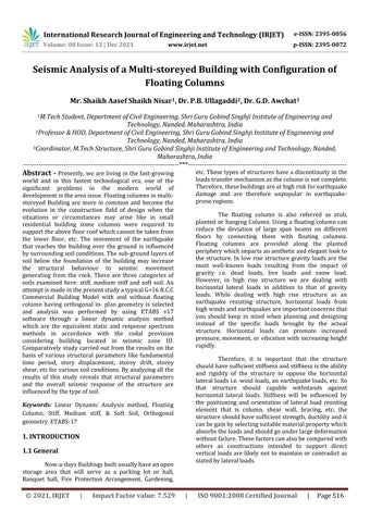
1.2 Floating Column Floating Columns: Floating columns are vertical members which, instead of resting on the foundation, rest on beams (due to architectural design/ site situation). It carries the load just like a normal column and transfers the load as a point load to the belowsupportingbeamwhichisreferredasgirderbeam or transfer beam and does not transfer loads directly to thefoundation. Therefore, they act aspointloadsover a beam It is not really floating; it's rest on a beam They arecapabletobearthegravityloadsifthetransfergirder is well suitable. The design of the transfer girders requires special attention in such structures, especially when they are located in an earthquake prone area. However,Floatingcolumnsdoesnotcreateanyproblem to bear gravity loads efficiently but the Transfer Girder should be of sufficient size (Stiffness) with very little displacement.Fig.1.1
[3] To Study the structural response for different cases invarioussoilcondition.
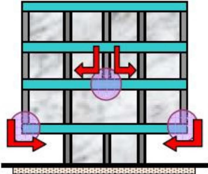
International Research Journal of Engineering and Technology (IRJET) e-ISSN: 2395-0056 Volume: 08 Issue: 12 | Dec 2021 www.irjet.net p-ISSN: 2395-0072 © 2021, IRJET | Impact Factor value: 7.529 | ISO 9001:2008 Certified Journal | Page518 Slab 20mm Beam 35mm Column 40mm Seismic Parameter SeismicZoneFactor,Z 0.16 Sitetype Stiff(I),MediumStiff(II)and SoftSoil(III) ImportanceFactor,I 1.2 ResponseReduction Factor 5 DampingRatio 5% 3.1 Structural Loads Consideration: 3.1.1 Wall Load a) ForGroundFloor=5.4KN/m b) ForalltypicalFloor=4.6KN/m c) ForTerraceFloor=2.6KN/m 3.1.2 Live Load a) ForallFloors=4KN/m2 b) ForTerrace=1.5KN/m2 3.1.3 Floor Finish a) ForallFloors=1.2KN/m2 b) ForTerrace=3.3KN/m2 c) ForBathroomorW.C.=2.6KN/m2 3.1.4 Wind Load In this Study, Wind Load can be determined over the height of the structure by Force Coefficient Method as perIS875 Part3(2015)asshownintable 2&table 3 a) Basic Wind Speed as per design code is Vb: 44 m/s b) CoefficientsK1,K3,K4:1 c) Kd:0.9,Ka: 0.8,Kc:0.9 d) TerrainCategory:Category 03 e) Force Coefficient, Cf: 1.25, 1.2 along X & Y Direction resp. based on a/b and h/b ratio for h/b>1ofChart IIofIS875 2015(Part 3) LateralTherefore,ForceovertheStorey(K)=CfxAexPd CfWhere,=ForceCoefficient Ae=EffectiveArea(m2) Pd=designwindpressure(KN/m2) (a)DesignWindSpeed,(Vz) Vz=VbxK1 xK2 xK3 xK4 Vz=Where,DesignWindSpeedinz direction,inm/s Vb=Basicwindspeed,inm/s K1=Probability(Risk)factor K2=Terrainroughnessandheightfactor K3=Topographyfactor(Basedonupwindslop) K4=Importancefactorforcyclonicregion (b)DesignWindPressure(Pd) Pz=0.6xVz2 PzWhere,=WindPressureatheight,inN/m2; Vz=designwindspeedatheightz,inm/s; Pd=KdxKaxKcxPz Kd=Where,WinddirectionalityFactor Ka=areaaveragingfactor Kc=Combinationfactor Pz=WindPressureatheight,inN/m2 Table 2: LateralForceovertheStoreyalongX Direction
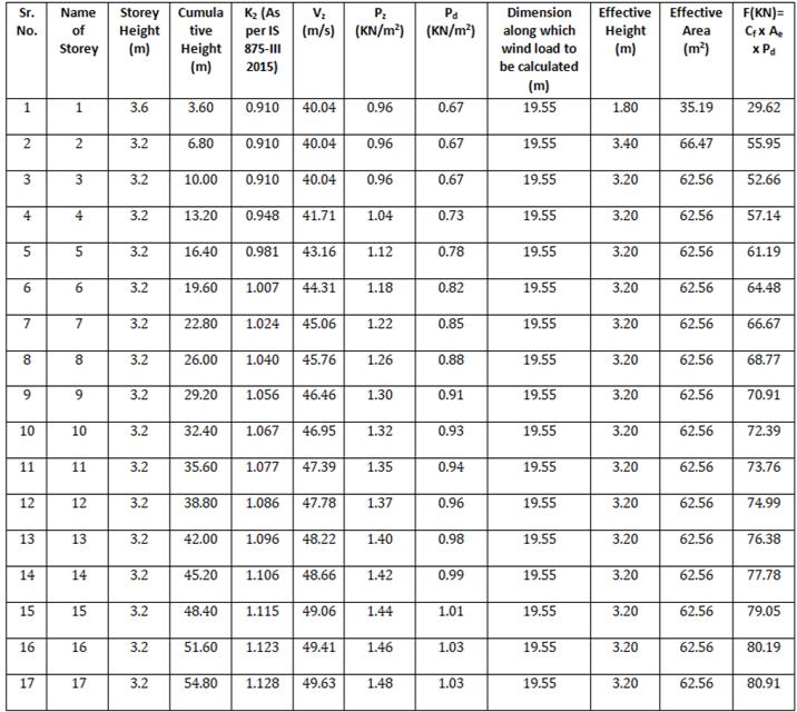
International Research Journal of Engineering and Technology (IRJET) e-ISSN: 2395-0056 Volume: 08 Issue: 12 | Dec 2021 www.irjet.net p-ISSN: 2395-0072 © 2021, IRJET | Impact Factor value: 7.529 | ISO 9001:2008 Certified Journal | Page519 Table 3: LateralForceovertheStoreyalongY Direction
5. RESULTS AND DISCUSSION Inthischapter,wewilldiscussaboutthevarious aspects of results of all the above mentioned Models Cases.Wewillseetheresultonthebasisofthefollowing structural aspects i.e. Fundamental time period, Storey Displacement,StoreyDrifts,StoreyOverturningMoment, StoreyShear,StoreyStiffness,etc.
3.1.5 Seismic Load Seismic load in this study is evaluated in compliancewiththedesigncodeIS 1893 2016(Part I)by considering seismic parameters as shown in table 1 and time period can be determined by using following Taequation,=0.09h/√d Therefore, Time period works out as 0.87 Sec and 1.12 SecinX&YDirectionrespectively. hWhere,=heightabovethegrounddefinedin7.6.2(a),inm& d = Base Dimension of a building at ground level in the projectedearthquakepath,inm.
Theloadcombinationhavetobeconsideredforanalysis asperIS1893 2016(Part I)cl.No.6.3.2.1
4. MODELLING CONFIGURATION
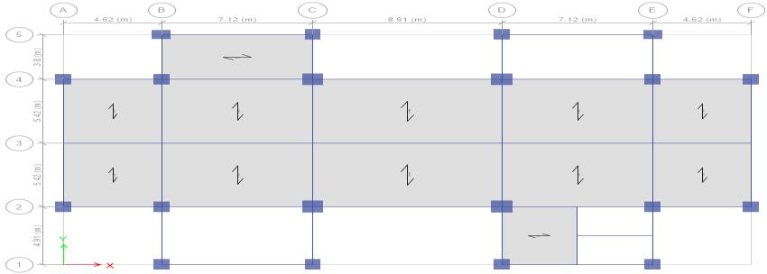
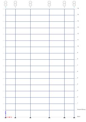
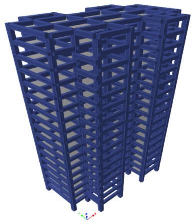
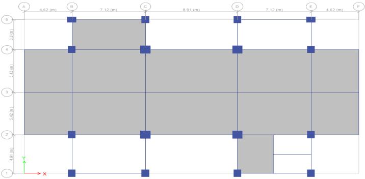
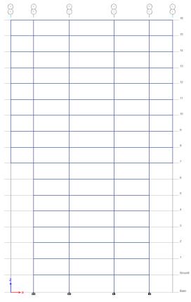
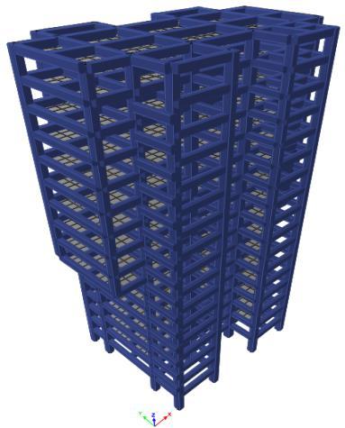
Fig.4.1(a):Planviewof(G+16)NormalR.C.Buildingmodel Fig.4.1(b):Elevationand3Dviewof(G+16)NormalR.C. Buildingmodel Fig.4.2(a):TypicalPlanviewofBuildingmodelwithFloating Columnforstiff,mediumstiffandsoftsoil Fig.4.2(b):TypicalElevationand3DviewofBuildingmodel withFloatingColumnforstiff,mediumstiffandsoftsoil
Followingresultshavebeenspecifiedinatabularaswell graphical illustration cases
in
5.1 Fundamental time period: It is defined as the time required to a structure tocompleteitsoneoscillation.Timeperiodinfluencedby thestiffnessoftheStructure.Buildingwithlessstiffness, there will be the more time period. However, Building withmorestiffnesstherewillbethelesstimeperiod.
Graph 1: ModalPeriodsforallcasesunderthe earthquakeforces
International Research Journal of Engineering and Technology (IRJET) e-ISSN: 2395-0056 Volume: 08 Issue: 12 | Dec 2021 www.irjet.net p-ISSN: 2395-0072 © 2021, IRJET | Impact Factor value: 7.529 | ISO 9001:2008 Certified Journal | Page520
The time period for the Structure with floating column is nearly same for different types of soil. Therefore the time period is not influenced by soil types
5.2 Storey Displacement Storey displacement is the complete displacement of any storey relative to the bottom surface storey, horizontal displacement is significant when structures areexposedtolateralloadslikeseismic&windloads.
for above
which I have consideredforthisprojectwork.
Fromtheabovegraphitcanbeseenthatformode 1,havingmaximumtimeperiod. The time period for the Structure without floating Column i.e. Normal Building is less compared with other model cases because it's having more stiffness.
Table 5.2: StoreyDisplacementforallcasesunderthe earthquakeforcealongX direction
Table 5.1: ModalPeriodsforallcasesunderthe earthquakeforces
Graph 2: StoreyDisplacementforallcasesunderthe earthquakeforcesalongX direction.
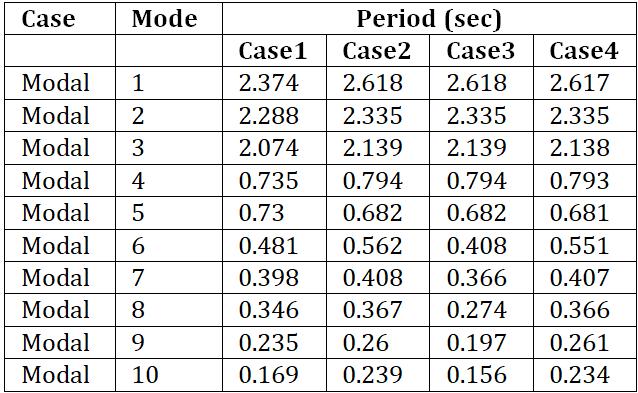
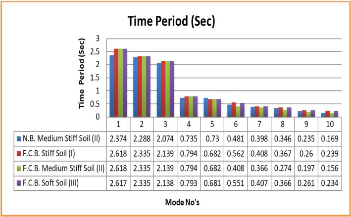
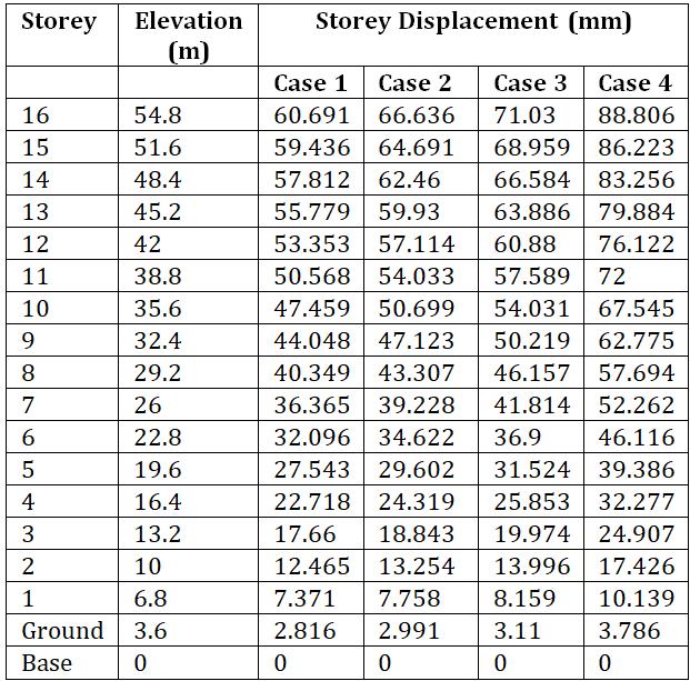
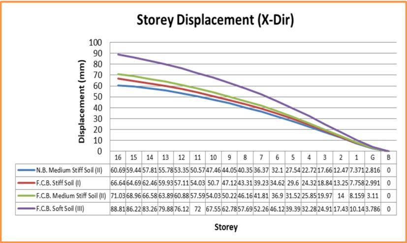
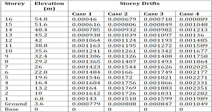
Table 5.4: StoreyDriftsforallcasesunderthe earthquakeforcesalongX direction Graph 4: StoreyDriftforallcasesundertheearthquake forcesalongX direction.
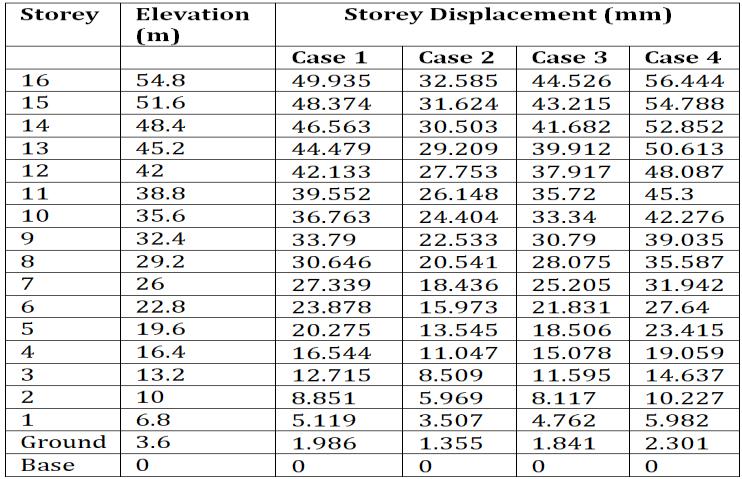
Table 5.3: StoreyDisplacementforallcasesunderthe earthquakeforceinY Direction
The maximum Storey displacements for the Structure with floating column in soft soil for stotey 16 is 88.806 mm along X direction whereas in Y direction is 56.444 mm which are the highest displacementvaluesamongallcases.
International Research Journal of Engineering and Technology (IRJET) e-ISSN: 2395-0056 Volume: 08 Issue: 12 | Dec 2021 www.irjet.net p-ISSN: 2395-0072 © 2021, IRJET | Impact Factor value: 7.529 | ISO 9001:2008 Certified Journal | Page521
5.3 Storey Drifts
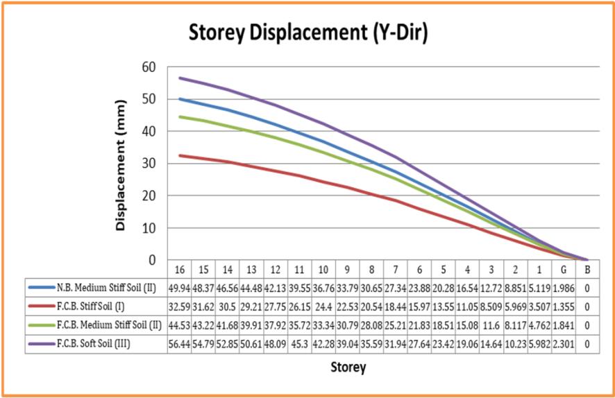
Graph 3: StoreyDisplacementforallcasesunderthe earthquakeforcesalongY direction.
Storey drift is a maximum lateral movement of one floor with relative to another floor. It is also known as an inter storey drift. According to Indian standard codalbook,Criteriaforearthquakehazardassessmentof seismic loads on various Structures, IS 1893 (Part I): 2016,Cl.No.7.11.1.1Pg.No.26thestorydriftinanystory should not exceed 0.004 times storey height. The worst height of the storey is 3.6m. Therefore, drift limit according to IS 1893 (Part I): 2016 is 0.004 X 3.6 m = 14.4mm
The percentile of lateral displacement along X direction of case 1 increased by 9.8%, 17.04%, 46.32%, of case 2, 3 and 4 respectively and about 34.75%,10.83%,and13.03%,alongY direction.
Behaviour of a graph is different for all above mentioned cases in various soil conditions as shown.
From above graph we can also observed that, maximum lateral displacements occurs in case of structures with floating Column in soft soil in both thedirectionsbecausestrengthandrigidityagainst lateralloadsarelessifwecomparethisresultswith model of structure for other types of soil considerations.
A graph above indicates that, Storey displacement of the Structure for R.C. Building model with and withoutfloatingcolumnfordifferenttypesofsoilin boththedirections.
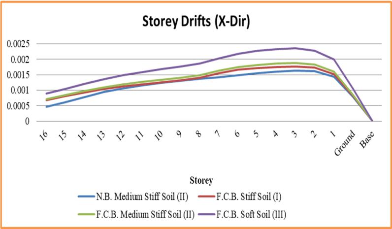
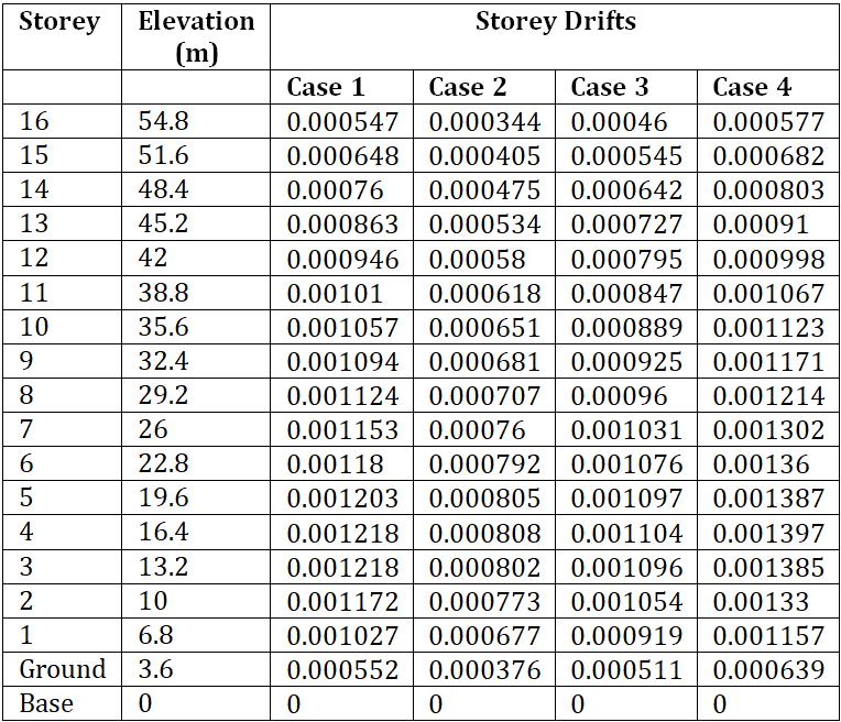
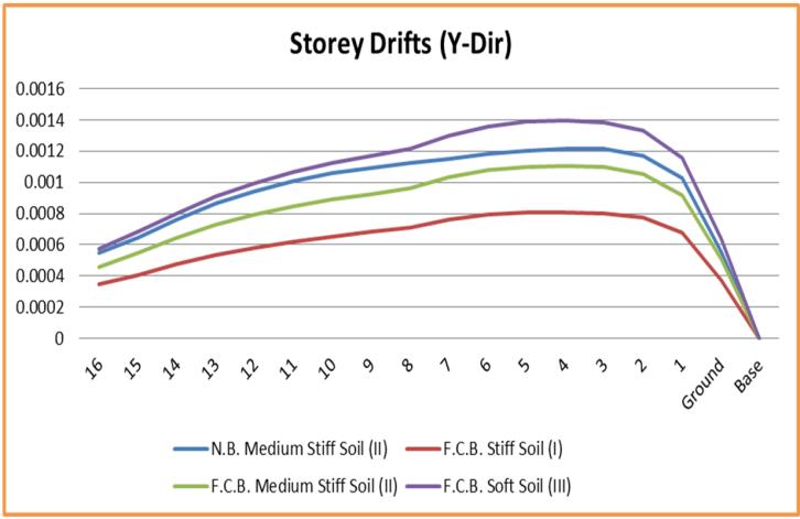
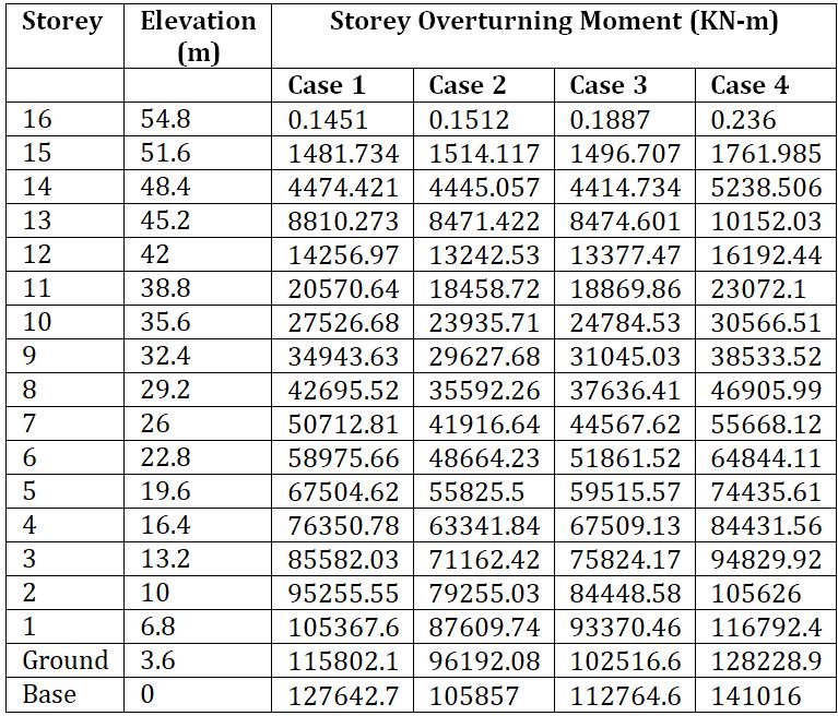
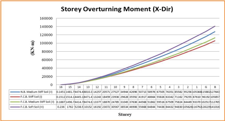
International Research Journal of Engineering and Technology (IRJET) e-ISSN: 2395-0056 Volume: 08 Issue: 12 | Dec 2021 www.irjet.net p-ISSN: 2395-0072 © 2021, IRJET | Impact Factor value: 7.529 | ISO 9001:2008 Certified Journal | Page522 Table 5.5: StoreyDriftsforallcasesunderthe earthquakeforcesalongY direction Graph 5: StoreyDriftforallcasesundertheearthquake forcesalongY direction. From graph above it seems that the storey drift is maximum for the structure with a floating column insoftsoilinboththedirections The maximum drift in X direction found to be for storey 3 whereas in Y direction found to be for storey 4. 5.4 Storey Overturning Moment Overturning moments in Structures are the moments which cause the structures to overturn due to thelateralforcesactingonthestructures.
Table 5.6: StoreyOverturning StoreyOverturning
Momentforallcases undertheearthquakeforcesalongX direction Graph 6:
Momentforallcasesunder theearthquakeforcesalongX direction.
Graph 8: storeyShearsforallcasesunderthe earthquakeforcesalongX direction.
International Research Journal of Engineering and Technology (IRJET) e-ISSN: 2395-0056 Volume: 08 Issue: 12 | Dec 2021 www.irjet.net p-ISSN: 2395-0072 © 2021, IRJET | Impact Factor value: 7.529 | ISO 9001:2008 Certified Journal | Page523
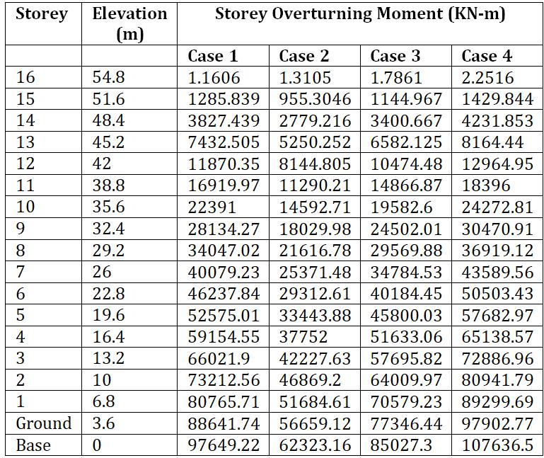
Table 5.7: StoreyOverturningMomentforallcases undertheearthquakeforcesalongY direction
Table 5.8: StoreyShearsforallcasesunderthe earthquakeforcesalongX direction
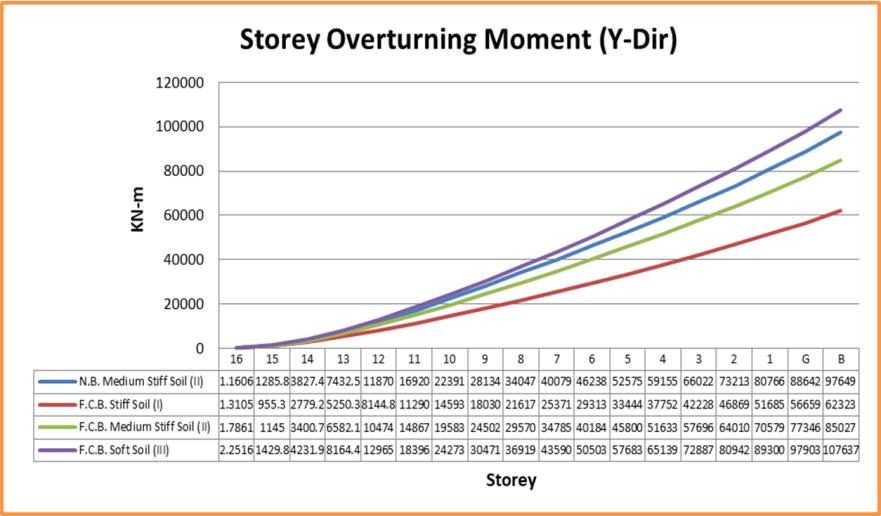
The maximum overturning moment for the structurewithfloatingcolumninsoftsoilforbaseis 141016 KN m along X direction and in Y direction is 107636.5 KN m which are the highest storey overturningmomentamongallcases.
5.5 Storey Shears The lateral forces which are acting at each floor due to the forces such as Seismic and wind force during anearthquakeareknownasstoryforces.
Graph 7: StoreyOverturningMomentforallcasesunder theearthquakeforcesalongY direction.
In the above graphs, in both X & Y directions, the behavior of graph is same to the model in Stiff, mediumstiffandsoftsoilasindicated
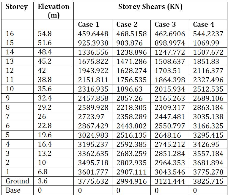
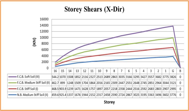
The above graphical representation shows the storeyshearforthestructurewithStiff,mediumstiff andsoftsoil. It can be seen from the above graph and obtained results that the storey shear decreases as storey levelincreases.
Storey stiffness is defined as the ability and rigidity of structure to oppose the lateral load i.e. an earthquake load and wind load. It is influenced by positioning,orientationandsizesoflateralloadresisting elements (i.e. Column, Shear wall, infill wall, Bracing, etc.)
Table 5.9: StoreyShearsforallcasesunderthe earthquakeforcesalongY direction
Graph 9: StoreyShearsforallcasesunderthe earthquakeforcesalongY direction.
International Research Journal of Engineering and Technology (IRJET) e-ISSN: 2395-0056 Volume: 08 Issue: 12 | Dec 2021 www.irjet.net p-ISSN: 2395-0072 © 2021, IRJET | Impact Factor value: 7.529 | ISO 9001:2008 Certified Journal | Page524
In this above graph the value of maximum Storey shearforasoftsoilstructureismoreincomparative tothestructureinstiffandmediumstiffsoil inboth thedirections becauseofthemomentsproducedfor thisstructureismaximum. The storey shear value of case 4 is decreased by 18.4%, 21.71%, and 1.3%, of case 3, 2 and 1 respectively.Therefore,thereisnoticeablevariation in floor shear force in the X direction with a variety ofsoilandstructures.
5.6 Storey Stiffness
Table 5.10: StoreyStiffnessforallcasesunderthe earthquakeforcesalongX direction
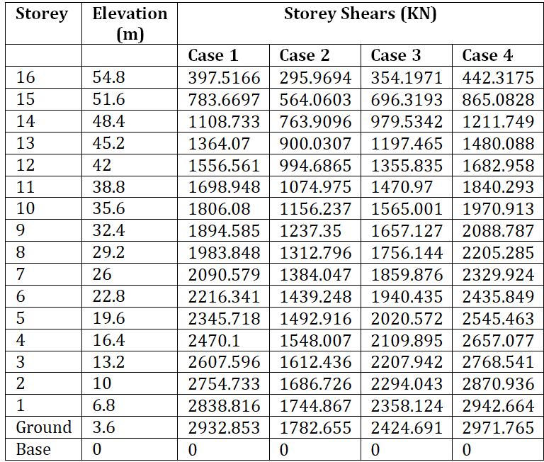
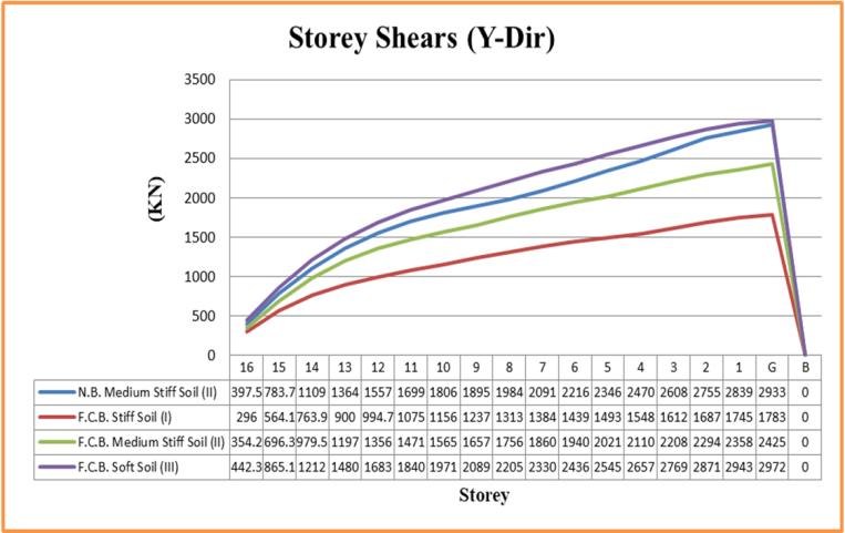
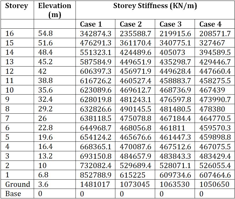
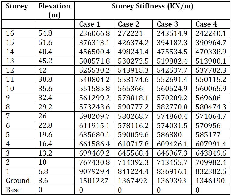
Table 5.11: StoreyStiffnessforallcasesunderthe earthquakeforcesalongY direction
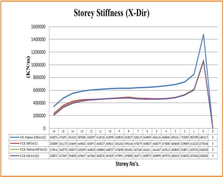
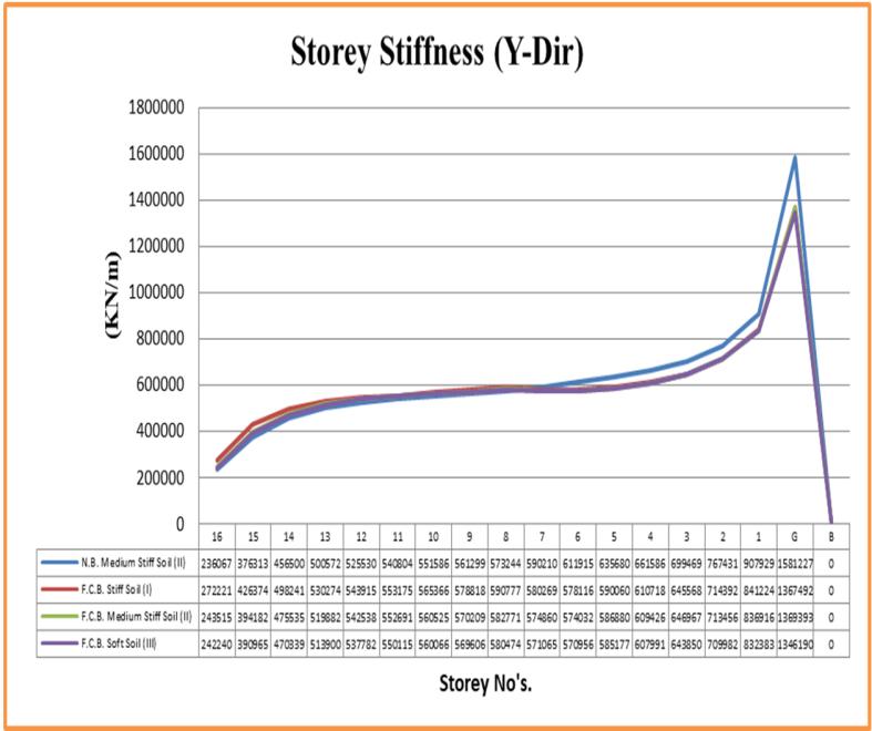
Fromtheabovegraph,wecanseethatthemaximum stiffness of the structure is for without floating columnbuilding(i.e.fornormalbuilding)andwhich is observed for Ground Storey i.e. 1481017 KN/m alongX directionandabout1581227KN/malongY direction.
Graph 10: StoreyStiffnessforallcasesunderthe earthquakeforcesalongX direction.
In this graph, the floating column building in medium Stiff and stiff soil shows similar behaviour inboththedirections.
6. CONCLUSIONS [1] The seismic analysis of a multi storeyed building with and without floating column for various soil condition is carried out by using ETABS v17 software through the linear Dynamic analysis methods which are the Equivalent static method and Response spectrum method according to standard specification of various design codes to the possible extent and from above results and discussion based on the various structural parametersfollowingconclusionscanbesummarizedfor thepresentstudy: [2]Fromtheresultsobtained,wehaveobservedthat by imparting of a floating column in the structure has a significantinfluencedonthetimeperiod.
International Research Journal of Engineering and Technology (IRJET) e-ISSN: 2395-0056 Volume: 08 Issue: 12 | Dec 2021 www.irjet.net p-ISSN: 2395-0072 © 2021, IRJET | Impact Factor value: 7.529 | ISO 9001:2008 Certified Journal | Page525
Graph 11: StoreyStiffnessforallcasesunderthe earthquakeforcesalongY direction
[3]AstructurelocatedinStiffsoilexhibitsloweststorey displacementinboththedirections(i.e.longitudinaland transverse) because stiffness against lateral loads are
Thegraphaboverepresentsthatthestoreystiffness of the structure for different cases in various soil conditions.
By analysing or assessing all results, it can be seen that the stiffness of the structure is also influenced bytypeofsoilavailable.
[10]TheSMRFwithproperpositioningandconsiderable sizes of lateral load resisting element are good enough not only to carry the gravity loads but also to resist the lateralforcessuchaswindandseismicforce.
[4]PradeepD.,ChethanVR,AshwiniBT(2017)“Seismic Analysis of Multi storey Building with Floating Columns using ETABS”, International Journal of Scientific DevelopmentandResearch(IJSDR)Volume2,Episode 9.
[5] G Hemanth, B Bhanupriya, A Ramakrishnaih (Nov 2017) “Earthquake analysis of Multi Storeyed Building withFloatingColumn’’,InternationalResearchJournalof Engineering and Technology (IRJET) Volume: 04 Issue: [6]11. Murtaza A. Rangwala and Sitesh Kumar Singh (May 2018) “Seismic Analysis of Multi Storey Frame with and Without Floating Columns”, International Journal of
[4] As per IS 1893 2016, the maximum storey displacementislimitedtothehighestvalueofH/500,the determined project results are within allowable displacement limit. So, the input data for this project is correctfortheanalysisanddesign.
International Research Journal of Engineering and Technology (IRJET) e-ISSN: 2395-0056 Volume: 08 Issue: 12 | Dec 2021 www.irjet.net p-ISSN: 2395-0072 © 2021, IRJET | Impact Factor value: 7.529 | ISO 9001:2008 Certified Journal | Page526
[1]DeekshithaRandDr.H.S.SureshChandra(June2017) “An Analysis of the Multi Storey Building with and without a Floating Column”, International Journal of Engineering Research & Technology (IJERT) Vol. 6 Episode06.
[13] Finally after this analysis and based on results obtained, we will recommend that the structure with floatingcolumnsinsoftsoilandmediumstiffsoilarenot suitable for seismic zone III. Also, if there is any pre existingstructure whichcannot be demolished,then the type of an improvement that can be applied to that structure like if the columns of the structure need to be thickened, or if that structure needs retrofitting techniques in the columns or beams, or if they need metal bracing to decrease the displacement or deformations,etc.
[11] In this project, we can see that the stiffness of a structure with floating column in soft soil is very low in both the directions. Therefore, the type of soil condition is also significant irrespective of stiffness to the [12]structure.Byanalyzing or assessing all the results, this study reveals that, storey displacement, storey drift, overturning moment, stiffness and the overall seismic responseofthestructureisinfluencedbythetypeofsoil.
[3]KandukuriSunithaandMr.KiranKumarReddy(Aug 2017) “Seismic Analysis of Multi storey Building with FloatingColumnbyusingTabs”,International Journal of Engineering Technology Science and Research (IJETSR) Volume4,Issue8.
[9] The overturning moment for the structure with floating column in soft soil is more as compared to medium stiff and stiff soil. Therefore it is undesirable conditiontoopposethelateralforcesduetolessstiffness intheeventofanearthquake.
[2] The structure can be analyzed by using non linear dynamic analysis methods such as time history method andPushoveranalysis.
[5] Also, we can see that storey displacement is influenced by changing soil strata for that type of structure because sufficient stiffness can be gain by meansofconsiderablesoilstrata.
[8]Thebetterperformanceishighlyeffectiveforfloating columnstructurewithstiffsoil.
[7] The structure can be analyzed by using advanced techniques.
[5] Further it should study by provision of other lateral load resisting element such as shear wall, steel bracing, [6]etc.Thestructurecanbeanalyzedforcompositeframe.
[6] Building model located in stiff and medium Stiff soil showedbetterperformanceintermsofmaximumstorey [7]displacement.Fromthe drift point of view, it is observed that, storey drift reduces at each floor of model in medium stiffandstiffsoilascomparedwithmodelinsoftsoil.
[3] The structure can also be analyzed for non orthogonalgeometry. [4] The structure can be analyzed for different height of thebuildingatdifferentlocations.
more if we compare this results with other model for differenttypesofsoilconsideration.
7. FUTURE SCOPE [1] The study can be extended for different structural configuration for highly earthquake prone zones in varioussoilconditions.
8. REFERENCES
[2]Bhukya NagarajuandM. Suneetha etal.,(Aug.2017) “DesignandAnalysisoftheG+12withFloatingColumns and without by using E TABS”, Anveshana’s Int. Journal ofResearchandPracticalEngineeringJournal(AIJREAS) Vol.2,Episode 8.
[8] Chandan Kumar, G. Rahul, V. Jayakumar and Prasidh E Prakash (2018) “Design, Structural Analysis and Performance Investigation on Static Seismic Analysis of G+10 Multi Storeyed Structures with and without Floating Column” A comparative study, International Journal of Pure and Applied Mathematics (IJPAM) Vol. 119No.16.
International Research Journal of Engineering and Technology (IRJET) e-ISSN: 2395-0056 Volume: 08 Issue: 12 | Dec 2021 www.irjet.net p-ISSN: 2395-0072 © 2021, IRJET | Impact Factor value: 7.529 | ISO 9001:2008 Certified Journal | Page527 Innovative Research in Science, Engineering and Technology(IJIRSET)Vol.7,Issue5.
[7] Mr.Gaurav Pandey and Mr. Sagar Jamle (Oct. 2018) “Optimum location of Floating Column in Multi Storey Building with Seismic Loading”, International Research Journal of Engineering and Technology (IRJET) Volume: 05Issue:10.
[9] Jaswinder Singh and Kshipra Kapoor et al., (March 2019) “Seismic Analysis of Multistoried Buildings with Floating Columns”, International Journal for Research in Applied Science & Engineering Technology (IJRASET) Vol.7Issue II