ofvoltagesagand
The National Institute of Engineering Mysuru, India. *** Abstract - Voltage sag, swell and harmonic distortion are the key power quality concerns addressed by the distribution network. The presence of non linear loads and renewable energy sources like solar, wind etc. is the reason for power quality issues. These necessitates theneedforthedevelopment of a power quality conditioner to compensate the effects of these power quality problems. Hence a Dynamic Voltage Restorer is developed and deployed to improve power quality by decreasing harmonics and adjusting for voltage swell and sag. A two stage energy conversion device connects the PV system to the PCC (Boost converter and inverter) system. The incremental inductance approach is usedtoextractmaximum power from solar energy. DVR control is achieved by regulating the load voltage under a variety of unexpected working conditions.ArtificialNeuralNetworkcontrollerbased DVR is carried out. The simulation results show that the Artificial Neural Networks based DVR with a THD of 2.84 % outperforms the PI based controller THD of disturbances.There cause swell.Sudden Literature survey Many papers have issues. A Fuzzy Logic based Dynamic Voltage restorer is proposed in [1]. A PID based control strategy for Power qualityimprovementispresentedin[2].In[3]PVsystemis usedasenergysourceforDVRinsteadofusingbattery.Made comparisonArtificialneuralnetwork(ANN)overHysteresis voltagecontroltechnique(HVCT).[4]providesanoverview oftheDVR control architectureaswell asitsmodelling. It demonstratesthatDVRscaneffectivelyrestorevoltage.The basicconstructionandoperationofDVRaredemonstrated. DVRcompensatingtechniquesareexploredindetail.In[5] PV source injected to DVR instead of using DC source or energystorageunitwiththedesireofencounterthevoltage sagandharmonics.Theincrementalconductancetechnique isselectedforMPPT.TheDVRminimizesharmonicsfrom loadvoltageaccurately.The THDcutdownundertheSLG fault condition with DVR. The author not going to discuss aboutthevoltageswell.In[6]differentcontroltechniques for Voltage Source Inverter (VSI) are introduced. Various control schemes are demonstrated and explored. The effectiveness of various strategies is assessed and contrasted. [7] presents a controller for DVR all right to increase the performance of OFF grid hybrid RES. The suggested controller adjusts the voltage between the DVR andtheloadinordertoreducesystemdisruptionandhence increasesystemperformance.Theresultsofacomparisonof PSO tuned PIandIntelligencetechnologiesforcontrolling DVRarepresented.In[8]presents,theDVRtechniquewas usedtoadjustforvoltagesagandvoltageswellinaPVgrid connected scheme. The fault analysis is complete is done, andaPIcontrollerapproachforcompensationofvoltagesag andswellhasbeendiscussedinthispaper.In[9]controller's is used to adjust the injected DVR voltage in order to enhance the voltage profile at both the PCC and the load during abnormal operating circumstances. The CS optimization technique is utilized to identify the ideal parameters of the two PI controllers introduced by minimizingtheISEbetweentheloadvoltageandareference voltage under various abnormal operating scenarios. [10] deliberatetheDVRcontrolmethodbyPIcontrollerwiththe seriescontrolmoduleandshuntcontrolmoduletoenhance thepowersystemquality.Thesuggestedcontroltechnique can be done using single phase compensation system or threephasecompensationmodules,buildupontherequired
International Research Journal of Engineering and Technology (IRJET) e ISSN: 2395 0056 Volume: 08 Issue: 12 | Dec 2021 www.irjet.net p ISSN: 2395 0072 © 2021, IRJET | Impact Factor value: 7.529 | ISO 9001:2008 Certified Journal | Page450
Voltage Quality Improvement using DVR with Novel Control Strategy Arjun joshi1, Rohit K Mathew2 1M. Tech (Power systems) Scholar, 2 Assistant Professor, Department of Electrical and Electronics Engineering
4.48%. Key Words: Voltagesag,Voltageswell,Harmonics,Dynamic Voltage Restorer, PI controller, Artificial Neural Network (ANN)controller. 1.INTRODUCTION TheElectricalenergygeneratedisinsufficienttomeetour country'sincreaseddemand.Asaresultofthereductionin conventional energy sources of supply, research into alternative energy sources has begun. The two common nature of non conventional energy sources are accidental variabilityandexistenceofstaticconverterwillcausepower qualityissues.Thesecharacteristicscancreatephenomena voltage sag and swells, including flickers, voltage sag and swells, high voltage and low voltage ride through, harmonics, poor power factor, and power quality issues, fault ride through, which are among the top concerns of utility harmonicincludemodernPowerscenarios.andandcontroller(PI),controlPointasplant(DVR)companies.Understudy,theDynamicVoltageRestorerisincorporatedintoapowergridassociatedtoaPVtohandlesolarenergy'sintermittencyandvariability,wellasgridfailuresleadbyvoltagesagsandswellattheofcommonconnection(PCC).ThesuggestedDVRtechniquehandlesaproportionalintegralanArtificialNeuralNetwork(ANN)controller,aninphasecompensationapproach.ThedescribeDVRtheelectricsystemareevaluatedinvariousfaultqualityissueshavebecomeamajorproblemtothepowersystem.Thesepowerqualityissuesmainlyvoltagequalitydisturbances.Voltagesag,swellanddistortionsarethemostcommonlyoccurring voltagequality
appearancesof shortcircuitorfluctuationsinloadaresomeofthem. 1.1
arevariousreasonsfor the
been reported for the power quality

International Research Journal of Engineering and Technology (IRJET) e ISSN: 2395 0056 Volume: 08 Issue: 12 | Dec 2021 www.irjet.net p ISSN: 2395 0072 © 2021, IRJET | Impact Factor value: 7.529 | ISO 9001:2008 Certified Journal | Page451
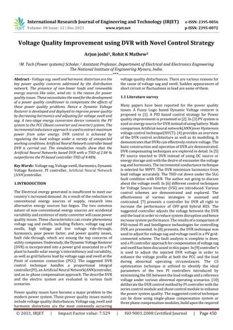
Fig 1: ProposedSystemBlockDiagram
voltagesagandvoltageswellcondition.[11]presentstwo promising controllers like PI controller and Park transformation controller to mitigate the voltage sag. Compare to PI controller, Park transformation controller givesbetterresults.[12]presentsthestudiesonfuzzypolar controllerforreducingthevoltagesagandswell.Theresults showthatfuzzypolarcontrollerisbetterthanPIcontroller. The simulation of discrete PWM based PI control and Hysteresis voltage controller (HVCT)for Dynamic Voltage Restorer using MATLAB has been presented in [13]. PV system is considered as input source to the DVR. Novel controlstrategyisusedtomitigatethepowerqualityissues likevoltagesag,swellandharmonics[14].[15]presentsa fuzzy control based DVR approach for compensation of voltage sag and voltage swell. Section 2 comprises of proposedsystem.Section3comprisessimulationstudies.
2 PROPOSED SYSTEM
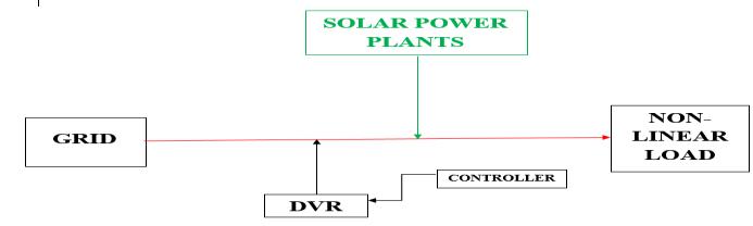
2.1 Dynamic Voltage Restorer: Fig-2: ShowsaDVR'sschematicdiagram. The mainprinciple oftheDVRistomaintain the constant loadvoltageduringsagorswellconditions.Dynamicvoltage restorer gives an economical solution to compensate the voltagesagandswellaswellasotherpowerqualityissues comparedtoothercustompowerdevices.Theblockdiagram shows in Figure 2 the components of Dynamic voltage restorer(DVR)whichiskeptinbetweenthegridandNon linear load where it mainly consists of 4 components like voltagesourceinverter,injectiontransformer,filter,energy storage element, controller among themcontrol system is thebrainoftheDVRwhichdetectsthevoltagesagandswell that occurs at the time of the power transmission from supply to load and then activates the Voltage source converter(VSC)togeneraterequiredvoltagewaveformof magnitudeandphaseangleinordertocalibratetheessential voltagesagorswellthatisoccurred.[3]Thevoltagesource inverter(VSC)converts the DC voltage from the energy storagesystemtoaregulatedthreephaseACvoltageduring voltagedisturbancestokeeptheloadvoltageatthedesired level.Inthisinvestigation,invertersidefilteringisfeatured. The high order harmonic currents are interrupted from gettingwithinthesequencetransformerusingthisfiltering system,loweringthevoltageurgencyonthetransformer 2.2 Solar Power Plant: Photovoltaiccellisadevicewhichconvertsvisiblelightinto direct current, solar panels or arrays can be formed by connecting the PV cell in series or parallel as per the requirement.Themajoradvantageofusingphotovoltaicisit iseco friendly,andthesolarenergyisunlimited.Oncethe PV module is installed it provides energy at essential cost withminimalmaintenance.Itiscomposedoffivesolarforms of 100kW each. The solar forms are interfaced to the distributiongridthroughathreephasePWMinverter.The PVarrayusedinthissimulationexaminecomprisesofseven (7) modules in series line and forty seven (47) parallel strings are used generate 100 kW at 1000 W/m2 solar irradiation and 380V output DC voltage. The Incremental Conductance(InC)techniqueisusedinthisstudy,whichcan be thought of as an upgraded variant of the famous P&O algorithm. This method was recommended to handle immediately changing climatic circumstances. All the five solarformsconnectedto30KVdistributiongridparallel.The detailsofPVpanelshownintheTable1.
specification
Table 1:SpecificationsofPVpanel Sl.no Parameters Specifications 1 Maximumpower/panel( ) 305W/panel 2 Maximumvoltage ) 54.7V 3 current/panelMaximum ) 5.58A 4 Irradiation 1000W/ 5 Celltemperature 25 6 NsandNp 7and47 7 Eachplantoutputpower 100kW 8 Totaloutputpower 5Farms=500kW 2.3 Proportional Integral Controller ThePIcontroller'sgeneralcharacteristicmodellingequation isasfollows: ��(��)=������(��)+����∫��(��)���� (1) y(t)isthecontroller'soutput,whilee(t)istheerrorsignal. The feedback PI controller has the advantage of being developedinsuchawaythatthesteadystateerroriszero. The plant is controlled by the feedback controller, which usesa weightedsumofthe errorsand theintegral ofthat value.Theproportionalresponseisobtainedbyaccumulate
International Research Journal of Engineering and Technology (IRJET) e ISSN: 2395 0056 Volume: 08 Issue: 12 | Dec 2021 www.irjet.net p ISSN: 2395 0072 © 2021, IRJET | Impact Factor value: 7.529 | ISO 9001:2008 Certified Journal | Page452
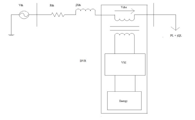
2.4 ANN Controller: Fig-4: SimulinkmodelofANNcontrollerforDVR.
the error by the proportional gain constant, Kp. The donationoftheintegraltermsisproportionaltothe error size and period. To get the accumulated offset that was previouslyrectified,multiplytheerrorbytheintegralgain, Ki, and then integrate it with 58. The values of Kp and Ki have a big impact on the PI controller's performance. For eachofthequadraturephases‘d'and‘q,'twoPIcontrollers wereemployedindividually.Forthed controller,KpandKi are40and154,respectively,andfortheq controller,they are 25 and 260. All of the gains are used to fine tune the error signal d and q, ensuring that it is durable and responsivetosystemdisruptions.
AccordingtoEquations(2),(3)and(4)thethreephaseload voltageacrossthesensitiveload(VSL)istransformedtoVd, Vq, and Vo using park transformation (4). The benefit of turning abs phases into dq0 components is that the zero sequencecomponentcanbeseparated.Thed qcomponents can be easily regulated in the nonappearance of a zero sequence component. They are compared to reference signalsVd ref,Vq reftogeneratetheerrorvoltage.Vdeisthe inequalityind referenceandsensitiveloadvoltageacquired by abc to dq0 transformation, and similarly q component error voltage (Vqe) is the inequality in q reference and sensitive load voltage obtained by abc to dq0 transformation.ThemodulatingsignalsfortheIGBTpulses aregeneratedbythecontrollers'outputsVd*andVq*.(5)(6)(7)
The DVR control based on ANN is shown in Figure 4 The controller'smainfunctionistodetectvoltagedisturbances, inject the voltage difference, and then return to standby mode once the disturbances have been erased. The phase lock loop (PLL) in this method tracks the sensitive load voltage.= (2) = (4)(3)
The dq0 to abc transformation is applied to these output signals.Equations(5),(6),and(7)explainhowtoconvertdq componentstoabcphasesinthenonappearanceofazero sequencecomponent(7).Thezerosequencecomponenthas been deactivated. These voltages (Vabc*) are utilized to improvetheperformanceoftheDynamicVoltageThedq0 to abc transformation is applied to these output signals. Equations (5), (6), and (7) explain how to convert dq componentstoabcphasesinthenonappearanceofazero sequencecomponent(7).Thezerosequencecomponenthas been deactivated. These voltages (Vabc*) are utilized to improvetheperformanceoftheDynamicVoltageRestorer bygeneratingpulsesinthevoltagesourceinverter.
3. SIMULATION RESULTS AND ANALYSIS: The DVR regulates the voltage about a 30 kV distribution grid system associated to bus B2 and has a 4MVA power rating. One feeder supplies electricity to a resident load attachedtobusB3,whichdepictsaplantthatisconstantly consuming oscillating currents and, as a result, creates voltageflicker.TheDVRinjectsanadequatevoltagetoadjust the voltage of the buses B1&B3. This voltage carry is accomplished by the coupling transformer's reactance, whichproducesasecondaryvoltagethatisinphasealong theprimaryvoltage(gridside).Duringasimulationtimeof threeseconds,thesimulationschemeexaminedinthiscase study abide of establishing two types faults of 0.3 second lengtheach.AsillustratedinFigure7,thefirsttypeoffaultis aswellvoltagethatoccursatintervalsofthedurationfrom 0.8secondsand1.1seconds,andthesecondtypeoffaultisa voltage sag that occurs at intervals of the duration from 1.25seconds and 1.55 seconds. The swell voltage defect is
Fig 3: SimulinkmodelPIcontrollerforDVR.
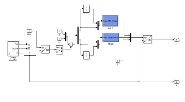


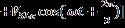


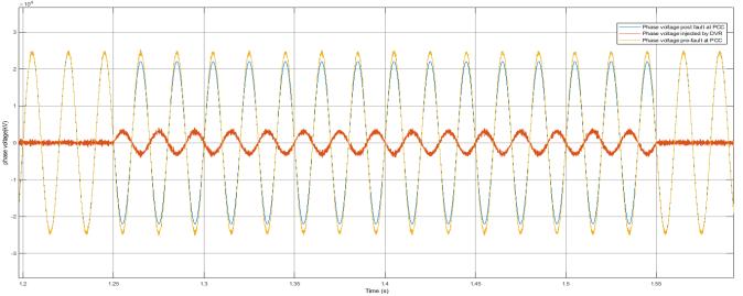
Fig 9: Phasevoltageduringvoltagesag
ThegridvoltageatthePointofcommonConnectionachieves steadystateafter2cycles,orroughly0.03seconds,current the scenario of voltage sag/dip happening at 1.25 sec, as showninFigure10.
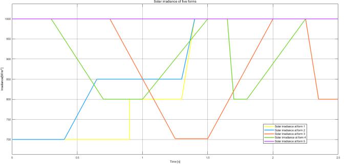
Fig 7: Atemperatureof25°C,thesolarirradiancesofthe fivesolarphotovoltaicfarmsweremeasured.
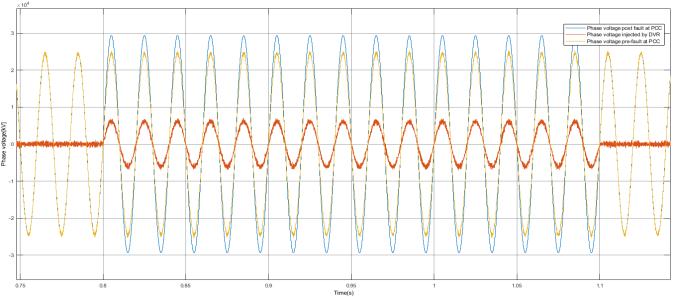
TheDVRinjectsacompensatingvoltagewhenthe voltage swell/raise occurs at 0.8 second, and the steadystateisreachedafteratransientofaround 0.11second,asshowninFigure9.
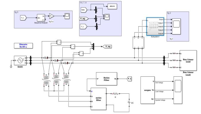
Fig 5:ModellingofTESTSYSTEMinMATLAB environment. DVR is connected in between grid and nonlinear load through injection transformer and filter.Five PV forms are connected to distribution grid through DC DC converter and inverter, all the five PV forms are connectedinparallel.Eachsolarplantgenerates100KW andoutputvoltageis380V.PVfarmof500kWconnected to grid shown in the figure 5 below. Each power plant operatesindifferentirradiationat25°C.
Fig 6: GridconnectedPhotovoltaicfarm
Fig 8: Phasevoltageduringvoltageswell
International Research Journal of Engineering and Technology (IRJET) e ISSN: 2395 0056 Volume: 08 Issue: 12 | Dec 2021 www.irjet.net p ISSN: 2395 0072 © 2021, IRJET | Impact Factor value: 7.529 | ISO 9001:2008 Certified Journal | Page453 modelledasa20%riseinnominalvoltage,whereasthesag voltageismodelledasa10%reductioninnominalvoltage. Table 2.Thesimulationparameters. Sl.no ParametersSystem values 1 Supply frequencyvoltageand 30kV,50Hz 2 Load =60ohm, =0.15mH 3 DCsupply 70kV 4 Filter 100 5 DVR 4MVA
Thedynamicvoltagerestorer(DVR)isinmodeofstandbyat thetimeofnormaloperation.AsshowninFigures8,9and10 whenavoltageswell/raisearise,thecontrolleridentifiesthe systemfailureandtheDVRinjectstherequiredvoltage.
3.1 Modelling of Test System in Mat Lab Environment.
3.2 Case studies [1]. VoltageSwellCondition [2]. VoltageSagCondition [3]. CombinedvoltageSwellandvoltageSagcondition
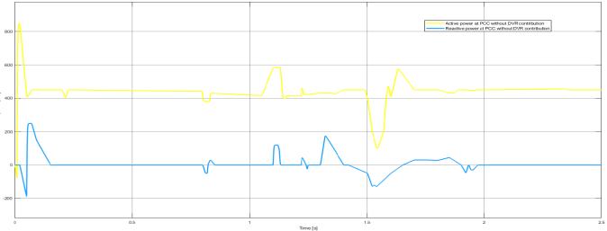
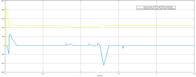
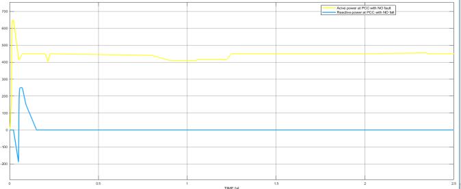
Figures 11,12 and 13 show the active power and reactive powercapabilities.WhentheDVRisnotinoperation,wecan witnessslightabandonandswayingintheactivepowerin Figure 11 and during the swell fault, although the oscillationsaretotallysuppressedduringtheDVRisturnon, as seen in Figure 12. The grid voltage produces a strong transient lasting 9 cycles when a sag fault occurs without DVR,whichisentirelydampedwhenDVRisused,asseenin figure12.
International Research Journal of Engineering and Technology (IRJET) e ISSN: 2395 0056 Volume: 08 Issue: 12 | Dec 2021 www.irjet.net p ISSN: 2395 0072 © 2021, IRJET | Impact Factor value: 7.529 | ISO 9001:2008 Certified Journal | Page454
Fig 13: ActiveandReactivepowerwithoutfault The reactive power (blue wave form) flow at the Point of common connection at the time both faults, as shown in Figures 11,12 and 13 at that time the voltage swell/raise fault, the waving of reactive power are very crucial than during the sag fault, where the overshoots are lesser in amplitudewiththeDVRdonation.Whenavoltagesagfault occurs,themovementofreactivepowerrisesinmagnitude, direction,anddurationwithouttheDVR.Thereactivepower reveals a high abandon at 1.39 seconds, analogues to an inoculation of +181.2 kVar, after a brief oscillation at the commencementofthefault.At1.535seconds,thereactive power dropped to 139.1 kVar, and after numerous oscillations, the system's natural activity was renewed finallyofthesagfaultat1.957seconds,asopposedtothe situation with DVR donation, when the oscillations were entirelysaturatedat1.69seconds.
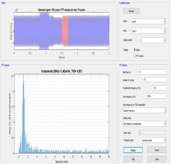
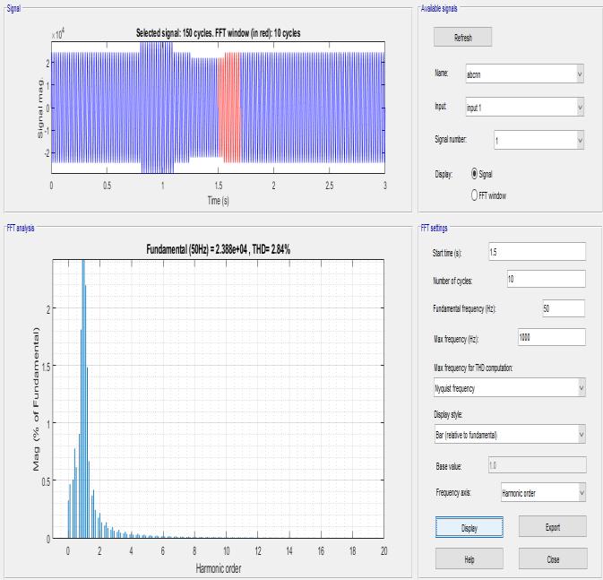
Fig 15:THDgraphforPIControlledDVR.
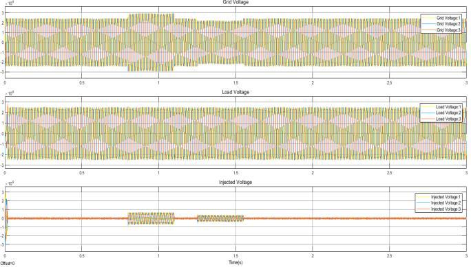
Fig 10: Waveformsforvoltagesagandvoltageswell
Fig 14: PerformanceofDVRwithANNController.
Fig 11: ActiveandReactivepowerwithoutDVR
Fig 12: ActiveandReactivepowerwithDVR

2. M.S.HaqueSunny,E.Hossain,M.AhmedandF.Un Noor, “Artificial Neural Network Based Dynamic Voltage Restorer for Improvement of Power Quality,” IEEE Energy Conversion Congress and Exposition,pp.5565 5572,2018.
5. RAMESH T. “Enhancing power quality of ANN controllerbasedPhotovoltaicsourceinjectedDVR.” InternationalJournalofEngineering&Technology, p.155 160,2018.
7. Wael S. Hassanein, Marwa M. Ahmed, M. Osama abedel Raouf,MohamedG.Ashmawy,MohamedI. Mosaad, “Performance improvement of off grid hybrid renewable energy system using dynamic voltagerestorer,”AlexandriaEngineeringJournal, Vol59,Issue3,pp1567 1581,2020.
4. SathishBabuP,KamarajN“PerformanceAnalysisof DVR Using ANN Controller for Voltage Quality Enhancement,” Applied Mechanics and Materials, pp.356 61,2014.
11. M.Faisal,M.S.Alam,M.I.M.Arafat,M.M.Rahman and S. M. G. Mostafa, “PI controller and park's transformation based control of dynamic voltage restorer for voltage sag minimization,” 9th
International Research Journal of Engineering and Technology (IRJET) e ISSN: 2395 0056 Volume: 08 Issue: 12 | Dec 2021 www.irjet.net p ISSN: 2395 0072 © 2021, IRJET | Impact Factor value: 7.529 | ISO 9001:2008 Certified Journal | Page455
10. A. Mohamed Eltamaly, Y. Sayed Mohamed, A. Mustafa El Sayed and A. N. Abd Elghaffar, “Enhancement of Power System Quality Using PI ControlTechniquewithDVRforMitigationVoltage Sag,” Twentieth International Middle East Power SystemsConference,pp.116 121,2018.
4. CONCLUSION Powerqualityissueshavebecomeamajorproblemtothe modern power system because of high penetration of renewableenergysources(solar)andnonlinearloadsThese power quality issues mainly include voltage quality disturbances like Voltage sag, swell and harmonic distortions.Aliteraturereviewondifferentaspectsofpower quality is conducted. Based on the literature survey the research objectives are defined. In this work DVR based powerqualityenhancementispresented.DetailedModelling of the solar PV cell and boost converter discussed. Simulation studies in MATLAB is conducted to assess the performanceoftheproposedcontroller.Fromtheresultsit is observed that with ANN based DVR the THD is 2.48%, against PI controller based DVR the THD is 4.28%. In comparison to the PI controller and ANN controller is the bestmethodforsolvingthepowerqualityissuesrelatedto sagandswell REFERENCES 1. Benali Abdelkrim, Khiat, Mounir Denai, Mouloud, “Voltageprofileandpowerqualityimprovementin photovoltaicfarmsintegratedmediumvoltagegrid using dynamic voltage restorer,” International Journal of Power Electronics and Drive Systems, vol.11,no.3,2020.
9. Mohamed I. Mosaad, M. Osama Abed El Raouf, Mahmoud A. Al Ahmar, Fahmy M. Bendary, “Optimal PI controller of DVR to enhance the performance of hybrid power system feeding a remote area in Egypt, Sustainable Cities and Society,”Vol47,2019.
6. Thana, H.S., Ruban Deva Prakash, “Use of neural network based DVR for the reduction of power quality issues in composite micro grid,” Ambient IntellHumanComput12,pp6285 6294,2021.
8. T Sridevi, Y Suri Babu, “Mitigation of Voltage Sag andSwellinAGridConnectedPVSystembyUsing DynamicVoltageRestorer,”InternationalJournalof Creative Research Thoughts, Vol 6, pp.659 665, APRIL2018.
3. A. M J, S. N and M. S. Shashikala, “Power Quality Enhancement using Dynamic Voltage Restorer (DVR)byArtificialNeuralNetworkandHysteresis VoltageControlTechniques,”GlobalConferencefor AdvancementinTechnology,pp.1 6,2019.
Fig 16: THDgraphforANNControlledDVR. Figure15and16showthevaluesofTHDwithPIcontroller andANNcontrollerrespectively.ItcanbeseenthatwithPI controllerthe THD is4.28% and with ANN controller it is 2.84%.UseofANNcontrollergivesthebettervalueofTHD therebyincreasingthesystemperformance. Table .3: LoadVoltageTHDAnalysis. Sl.No System THD in % 1 Withoutcontroller 24.98% 2 WithPIcontroller 4.28% 3 WithANNcontroller 2.84% Inthissectiontwodifferentcontrollersviz.,PIcontrollerand ANNcontrollerhavebeenusedtoanalyzeTHDvalue.These controllers are used to give signals to VSC in case of fault condition.Fromtheanalysisitcanbeconcludedthattheuse of ANN controller provides lower value of THD thereby increasingsystemperformance.
12. Pujiantara, Margo, Heri, P.M. Ashari, Mochamad, Hiyama, “Voltage Sag Correction Using Dynamic Voltage Restorer Based Fuzzy Polar Controller,” Second International Conference on Innovative Computing,InformationandControl,2007.
13. G. S. Dua and R. Kaur, “Enhancement of Power QualityindistributionnetworkusingDVR,”Annual IEEEIndiaConference,pp.1 6,2015.
International Research Journal of Engineering and Technology (IRJET) e ISSN: 2395 0056 Volume: 08 Issue: 12 | Dec 2021 www.irjet.net p ISSN: 2395 0072 © 2021, IRJET | Impact Factor value: 7.529 | ISO 9001:2008 Certified Journal | Page456 International Forum on Strategic Technology, pp.276 279,2014.
14. Syed, Suraya, Sujatha, P. Kumar, “Contemporary Control of DG Integrated DVR for Sag, Swell and Harmonic Mitigation,” International Journal of ElectricalandComputerEngineering,VL 8,2018.